EP4414465A1 - Installation de recuit de finition pour tôle d'acier électromagnétique, procédé de recuit de finition et procédé de production pour tôle d'acier électromagnétique, et tôle d'acier électromagnétique non orientée - Google Patents
Installation de recuit de finition pour tôle d'acier électromagnétique, procédé de recuit de finition et procédé de production pour tôle d'acier électromagnétique, et tôle d'acier électromagnétique non orientée Download PDFInfo
- Publication number
- EP4414465A1 EP4414465A1 EP22889745.0A EP22889745A EP4414465A1 EP 4414465 A1 EP4414465 A1 EP 4414465A1 EP 22889745 A EP22889745 A EP 22889745A EP 4414465 A1 EP4414465 A1 EP 4414465A1
- Authority
- EP
- European Patent Office
- Prior art keywords
- steel sheet
- region
- finish annealing
- annealing
- mass
- Prior art date
- Legal status (The legal status is an assumption and is not a legal conclusion. Google has not performed a legal analysis and makes no representation as to the accuracy of the status listed.)
- Pending
Links
Images




Classifications
-
- C—CHEMISTRY; METALLURGY
- C21—METALLURGY OF IRON
- C21D—MODIFYING THE PHYSICAL STRUCTURE OF FERROUS METALS; GENERAL DEVICES FOR HEAT TREATMENT OF FERROUS OR NON-FERROUS METALS OR ALLOYS; MAKING METAL MALLEABLE, e.g. BY DECARBURISATION OR TEMPERING
- C21D9/00—Heat treatment, e.g. annealing, hardening, quenching or tempering, adapted for particular articles; Furnaces therefor
- C21D9/0062—Heat-treating apparatus with a cooling or quenching zone
-
- C—CHEMISTRY; METALLURGY
- C21—METALLURGY OF IRON
- C21D—MODIFYING THE PHYSICAL STRUCTURE OF FERROUS METALS; GENERAL DEVICES FOR HEAT TREATMENT OF FERROUS OR NON-FERROUS METALS OR ALLOYS; MAKING METAL MALLEABLE, e.g. BY DECARBURISATION OR TEMPERING
- C21D8/00—Modifying the physical properties of ferrous metals or ferrous alloys by deformation combined with, or followed by, heat treatment
- C21D8/12—Modifying the physical properties of ferrous metals or ferrous alloys by deformation combined with, or followed by, heat treatment during manufacturing of articles with special electromagnetic properties
-
- C—CHEMISTRY; METALLURGY
- C21—METALLURGY OF IRON
- C21D—MODIFYING THE PHYSICAL STRUCTURE OF FERROUS METALS; GENERAL DEVICES FOR HEAT TREATMENT OF FERROUS OR NON-FERROUS METALS OR ALLOYS; MAKING METAL MALLEABLE, e.g. BY DECARBURISATION OR TEMPERING
- C21D1/00—General methods or devices for heat treatment, e.g. annealing, hardening, quenching or tempering
- C21D1/74—Methods of treatment in inert gas, controlled atmosphere, vacuum or pulverulent material
-
- C—CHEMISTRY; METALLURGY
- C21—METALLURGY OF IRON
- C21D—MODIFYING THE PHYSICAL STRUCTURE OF FERROUS METALS; GENERAL DEVICES FOR HEAT TREATMENT OF FERROUS OR NON-FERROUS METALS OR ALLOYS; MAKING METAL MALLEABLE, e.g. BY DECARBURISATION OR TEMPERING
- C21D1/00—General methods or devices for heat treatment, e.g. annealing, hardening, quenching or tempering
- C21D1/74—Methods of treatment in inert gas, controlled atmosphere, vacuum or pulverulent material
- C21D1/76—Adjusting the composition of the atmosphere
-
- C—CHEMISTRY; METALLURGY
- C21—METALLURGY OF IRON
- C21D—MODIFYING THE PHYSICAL STRUCTURE OF FERROUS METALS; GENERAL DEVICES FOR HEAT TREATMENT OF FERROUS OR NON-FERROUS METALS OR ALLOYS; MAKING METAL MALLEABLE, e.g. BY DECARBURISATION OR TEMPERING
- C21D6/00—Heat treatment of ferrous alloys
- C21D6/005—Heat treatment of ferrous alloys containing Mn
-
- C—CHEMISTRY; METALLURGY
- C21—METALLURGY OF IRON
- C21D—MODIFYING THE PHYSICAL STRUCTURE OF FERROUS METALS; GENERAL DEVICES FOR HEAT TREATMENT OF FERROUS OR NON-FERROUS METALS OR ALLOYS; MAKING METAL MALLEABLE, e.g. BY DECARBURISATION OR TEMPERING
- C21D6/00—Heat treatment of ferrous alloys
- C21D6/008—Heat treatment of ferrous alloys containing Si
-
- C—CHEMISTRY; METALLURGY
- C21—METALLURGY OF IRON
- C21D—MODIFYING THE PHYSICAL STRUCTURE OF FERROUS METALS; GENERAL DEVICES FOR HEAT TREATMENT OF FERROUS OR NON-FERROUS METALS OR ALLOYS; MAKING METAL MALLEABLE, e.g. BY DECARBURISATION OR TEMPERING
- C21D8/00—Modifying the physical properties of ferrous metals or ferrous alloys by deformation combined with, or followed by, heat treatment
- C21D8/12—Modifying the physical properties of ferrous metals or ferrous alloys by deformation combined with, or followed by, heat treatment during manufacturing of articles with special electromagnetic properties
- C21D8/1216—Modifying the physical properties of ferrous metals or ferrous alloys by deformation combined with, or followed by, heat treatment during manufacturing of articles with special electromagnetic properties characterised by the working steps
- C21D8/1233—Cold rolling
-
- C—CHEMISTRY; METALLURGY
- C21—METALLURGY OF IRON
- C21D—MODIFYING THE PHYSICAL STRUCTURE OF FERROUS METALS; GENERAL DEVICES FOR HEAT TREATMENT OF FERROUS OR NON-FERROUS METALS OR ALLOYS; MAKING METAL MALLEABLE, e.g. BY DECARBURISATION OR TEMPERING
- C21D8/00—Modifying the physical properties of ferrous metals or ferrous alloys by deformation combined with, or followed by, heat treatment
- C21D8/12—Modifying the physical properties of ferrous metals or ferrous alloys by deformation combined with, or followed by, heat treatment during manufacturing of articles with special electromagnetic properties
- C21D8/1244—Modifying the physical properties of ferrous metals or ferrous alloys by deformation combined with, or followed by, heat treatment during manufacturing of articles with special electromagnetic properties characterised by the heat treatment
-
- C—CHEMISTRY; METALLURGY
- C21—METALLURGY OF IRON
- C21D—MODIFYING THE PHYSICAL STRUCTURE OF FERROUS METALS; GENERAL DEVICES FOR HEAT TREATMENT OF FERROUS OR NON-FERROUS METALS OR ALLOYS; MAKING METAL MALLEABLE, e.g. BY DECARBURISATION OR TEMPERING
- C21D8/00—Modifying the physical properties of ferrous metals or ferrous alloys by deformation combined with, or followed by, heat treatment
- C21D8/12—Modifying the physical properties of ferrous metals or ferrous alloys by deformation combined with, or followed by, heat treatment during manufacturing of articles with special electromagnetic properties
- C21D8/1244—Modifying the physical properties of ferrous metals or ferrous alloys by deformation combined with, or followed by, heat treatment during manufacturing of articles with special electromagnetic properties characterised by the heat treatment
- C21D8/1272—Final recrystallisation annealing
-
- C—CHEMISTRY; METALLURGY
- C21—METALLURGY OF IRON
- C21D—MODIFYING THE PHYSICAL STRUCTURE OF FERROUS METALS; GENERAL DEVICES FOR HEAT TREATMENT OF FERROUS OR NON-FERROUS METALS OR ALLOYS; MAKING METAL MALLEABLE, e.g. BY DECARBURISATION OR TEMPERING
- C21D9/00—Heat treatment, e.g. annealing, hardening, quenching or tempering, adapted for particular articles; Furnaces therefor
- C21D9/46—Heat treatment, e.g. annealing, hardening, quenching or tempering, adapted for particular articles; Furnaces therefor for sheet metals
-
- C—CHEMISTRY; METALLURGY
- C21—METALLURGY OF IRON
- C21D—MODIFYING THE PHYSICAL STRUCTURE OF FERROUS METALS; GENERAL DEVICES FOR HEAT TREATMENT OF FERROUS OR NON-FERROUS METALS OR ALLOYS; MAKING METAL MALLEABLE, e.g. BY DECARBURISATION OR TEMPERING
- C21D9/00—Heat treatment, e.g. annealing, hardening, quenching or tempering, adapted for particular articles; Furnaces therefor
- C21D9/52—Heat treatment, e.g. annealing, hardening, quenching or tempering, adapted for particular articles; Furnaces therefor for wires; for strips ; for rods of unlimited length
- C21D9/54—Furnaces for treating strips or wire
- C21D9/56—Continuous furnaces for strip or wire
-
- C—CHEMISTRY; METALLURGY
- C21—METALLURGY OF IRON
- C21D—MODIFYING THE PHYSICAL STRUCTURE OF FERROUS METALS; GENERAL DEVICES FOR HEAT TREATMENT OF FERROUS OR NON-FERROUS METALS OR ALLOYS; MAKING METAL MALLEABLE, e.g. BY DECARBURISATION OR TEMPERING
- C21D9/00—Heat treatment, e.g. annealing, hardening, quenching or tempering, adapted for particular articles; Furnaces therefor
- C21D9/52—Heat treatment, e.g. annealing, hardening, quenching or tempering, adapted for particular articles; Furnaces therefor for wires; for strips ; for rods of unlimited length
- C21D9/54—Furnaces for treating strips or wire
- C21D9/56—Continuous furnaces for strip or wire
- C21D9/561—Continuous furnaces for strip or wire with a controlled atmosphere or vacuum
-
- C—CHEMISTRY; METALLURGY
- C21—METALLURGY OF IRON
- C21D—MODIFYING THE PHYSICAL STRUCTURE OF FERROUS METALS; GENERAL DEVICES FOR HEAT TREATMENT OF FERROUS OR NON-FERROUS METALS OR ALLOYS; MAKING METAL MALLEABLE, e.g. BY DECARBURISATION OR TEMPERING
- C21D9/00—Heat treatment, e.g. annealing, hardening, quenching or tempering, adapted for particular articles; Furnaces therefor
- C21D9/52—Heat treatment, e.g. annealing, hardening, quenching or tempering, adapted for particular articles; Furnaces therefor for wires; for strips ; for rods of unlimited length
- C21D9/54—Furnaces for treating strips or wire
- C21D9/56—Continuous furnaces for strip or wire
- C21D9/573—Continuous furnaces for strip or wire with cooling
-
- C—CHEMISTRY; METALLURGY
- C22—METALLURGY; FERROUS OR NON-FERROUS ALLOYS; TREATMENT OF ALLOYS OR NON-FERROUS METALS
- C22C—ALLOYS
- C22C38/00—Ferrous alloys, e.g. steel alloys
- C22C38/001—Ferrous alloys, e.g. steel alloys containing N
-
- C—CHEMISTRY; METALLURGY
- C22—METALLURGY; FERROUS OR NON-FERROUS ALLOYS; TREATMENT OF ALLOYS OR NON-FERROUS METALS
- C22C—ALLOYS
- C22C38/00—Ferrous alloys, e.g. steel alloys
- C22C38/02—Ferrous alloys, e.g. steel alloys containing silicon
-
- C—CHEMISTRY; METALLURGY
- C22—METALLURGY; FERROUS OR NON-FERROUS ALLOYS; TREATMENT OF ALLOYS OR NON-FERROUS METALS
- C22C—ALLOYS
- C22C38/00—Ferrous alloys, e.g. steel alloys
- C22C38/04—Ferrous alloys, e.g. steel alloys containing manganese
-
- C—CHEMISTRY; METALLURGY
- C22—METALLURGY; FERROUS OR NON-FERROUS ALLOYS; TREATMENT OF ALLOYS OR NON-FERROUS METALS
- C22C—ALLOYS
- C22C38/00—Ferrous alloys, e.g. steel alloys
- C22C38/06—Ferrous alloys, e.g. steel alloys containing aluminium
-
- C—CHEMISTRY; METALLURGY
- C22—METALLURGY; FERROUS OR NON-FERROUS ALLOYS; TREATMENT OF ALLOYS OR NON-FERROUS METALS
- C22C—ALLOYS
- C22C38/00—Ferrous alloys, e.g. steel alloys
- C22C38/60—Ferrous alloys, e.g. steel alloys containing lead, selenium, tellurium, or antimony, or more than 0.04% by weight of sulfur
-
- F—MECHANICAL ENGINEERING; LIGHTING; HEATING; WEAPONS; BLASTING
- F27—FURNACES; KILNS; OVENS; RETORTS
- F27B—FURNACES, KILNS, OVENS OR RETORTS IN GENERAL; OPEN SINTERING OR LIKE APPARATUS
- F27B9/00—Furnaces through which the charge is moved mechanically, e.g. of tunnel type; Similar furnaces in which the charge moves by gravity
- F27B9/02—Furnaces through which the charge is moved mechanically, e.g. of tunnel type; Similar furnaces in which the charge moves by gravity of multiple-track type; of multiple-chamber type; Combinations of furnaces
- F27B9/028—Multi-chamber type furnaces
-
- F—MECHANICAL ENGINEERING; LIGHTING; HEATING; WEAPONS; BLASTING
- F27—FURNACES; KILNS; OVENS; RETORTS
- F27B—FURNACES, KILNS, OVENS OR RETORTS IN GENERAL; OPEN SINTERING OR LIKE APPARATUS
- F27B9/00—Furnaces through which the charge is moved mechanically, e.g. of tunnel type; Similar furnaces in which the charge moves by gravity
- F27B9/02—Furnaces through which the charge is moved mechanically, e.g. of tunnel type; Similar furnaces in which the charge moves by gravity of multiple-track type; of multiple-chamber type; Combinations of furnaces
- F27B9/029—Multicellular type furnaces constructed with add-on modules
-
- F—MECHANICAL ENGINEERING; LIGHTING; HEATING; WEAPONS; BLASTING
- F27—FURNACES; KILNS; OVENS; RETORTS
- F27B—FURNACES, KILNS, OVENS OR RETORTS IN GENERAL; OPEN SINTERING OR LIKE APPARATUS
- F27B9/00—Furnaces through which the charge is moved mechanically, e.g. of tunnel type; Similar furnaces in which the charge moves by gravity
- F27B9/30—Details, accessories or equipment specially adapted for furnaces of these types
- F27B9/40—Arrangements of controlling or monitoring devices
-
- F—MECHANICAL ENGINEERING; LIGHTING; HEATING; WEAPONS; BLASTING
- F27—FURNACES; KILNS; OVENS; RETORTS
- F27D—DETAILS OR ACCESSORIES OF FURNACES, KILNS, OVENS OR RETORTS, IN SO FAR AS THEY ARE OF KINDS OCCURRING IN MORE THAN ONE KIND OF FURNACE
- F27D19/00—Arrangements of controlling devices
-
- F—MECHANICAL ENGINEERING; LIGHTING; HEATING; WEAPONS; BLASTING
- F27—FURNACES; KILNS; OVENS; RETORTS
- F27D—DETAILS OR ACCESSORIES OF FURNACES, KILNS, OVENS OR RETORTS, IN SO FAR AS THEY ARE OF KINDS OCCURRING IN MORE THAN ONE KIND OF FURNACE
- F27D21/00—Arrangement of monitoring devices; Arrangement of safety devices
-
- F—MECHANICAL ENGINEERING; LIGHTING; HEATING; WEAPONS; BLASTING
- F27—FURNACES; KILNS; OVENS; RETORTS
- F27D—DETAILS OR ACCESSORIES OF FURNACES, KILNS, OVENS OR RETORTS, IN SO FAR AS THEY ARE OF KINDS OCCURRING IN MORE THAN ONE KIND OF FURNACE
- F27D7/00—Forming, maintaining or circulating atmospheres in heating chambers
- F27D7/06—Forming or maintaining special atmospheres or vacuum within heating chambers
-
- H—ELECTRICITY
- H01—ELECTRIC ELEMENTS
- H01F—MAGNETS; INDUCTANCES; TRANSFORMERS; SELECTION OF MATERIALS FOR THEIR MAGNETIC PROPERTIES
- H01F1/00—Magnets or magnetic bodies characterised by the magnetic materials therefor; Selection of materials for their magnetic properties
- H01F1/01—Magnets or magnetic bodies characterised by the magnetic materials therefor; Selection of materials for their magnetic properties of inorganic materials
- H01F1/03—Magnets or magnetic bodies characterised by the magnetic materials therefor; Selection of materials for their magnetic properties of inorganic materials characterised by their coercivity
- H01F1/12—Magnets or magnetic bodies characterised by the magnetic materials therefor; Selection of materials for their magnetic properties of inorganic materials characterised by their coercivity of soft-magnetic materials
- H01F1/14—Magnets or magnetic bodies characterised by the magnetic materials therefor; Selection of materials for their magnetic properties of inorganic materials characterised by their coercivity of soft-magnetic materials metals or alloys
- H01F1/147—Alloys characterised by their composition
-
- H—ELECTRICITY
- H01—ELECTRIC ELEMENTS
- H01F—MAGNETS; INDUCTANCES; TRANSFORMERS; SELECTION OF MATERIALS FOR THEIR MAGNETIC PROPERTIES
- H01F1/00—Magnets or magnetic bodies characterised by the magnetic materials therefor; Selection of materials for their magnetic properties
- H01F1/01—Magnets or magnetic bodies characterised by the magnetic materials therefor; Selection of materials for their magnetic properties of inorganic materials
- H01F1/03—Magnets or magnetic bodies characterised by the magnetic materials therefor; Selection of materials for their magnetic properties of inorganic materials characterised by their coercivity
- H01F1/12—Magnets or magnetic bodies characterised by the magnetic materials therefor; Selection of materials for their magnetic properties of inorganic materials characterised by their coercivity of soft-magnetic materials
- H01F1/14—Magnets or magnetic bodies characterised by the magnetic materials therefor; Selection of materials for their magnetic properties of inorganic materials characterised by their coercivity of soft-magnetic materials metals or alloys
- H01F1/147—Alloys characterised by their composition
- H01F1/14766—Fe-Si based alloys
- H01F1/14775—Fe-Si based alloys in the form of sheets
-
- Y—GENERAL TAGGING OF NEW TECHNOLOGICAL DEVELOPMENTS; GENERAL TAGGING OF CROSS-SECTIONAL TECHNOLOGIES SPANNING OVER SEVERAL SECTIONS OF THE IPC; TECHNICAL SUBJECTS COVERED BY FORMER USPC CROSS-REFERENCE ART COLLECTIONS [XRACs] AND DIGESTS
- Y02—TECHNOLOGIES OR APPLICATIONS FOR MITIGATION OR ADAPTATION AGAINST CLIMATE CHANGE
- Y02P—CLIMATE CHANGE MITIGATION TECHNOLOGIES IN THE PRODUCTION OR PROCESSING OF GOODS
- Y02P10/00—Technologies related to metal processing
- Y02P10/20—Recycling
Definitions
- the present invention relates to a finish annealing facility that is preferably used for the production of electrical steel sheets, a finish annealing method and an electrical steel sheet production method that use this facility, and a non-oriented electrical steel sheet with excellent magnetic properties.
- An electrical steel sheet for example, a non-oriented electrical steel sheet is typically produced as follows: Steel adjusted to a predetermined ingredient composition is melted to be formed into a steel material (slab) by a method such as a continuous casting method, and then the slab is subjected to hot-rolling to form a hot-rolled sheet.
- the hot-rolled sheet is subj ected to hot-band annealing as necessary, and then one cold rolling or two or more cold rollings with intermediate annealing between each cold rolling is performed thereon to obtain a cold-rolled sheet having a final sheet thickness (product sheet thickness).
- the cold-rolled sheet is then subjected to finish annealing for imparting desired magnetic properties thereto, and an insulation coating is formed thereon as necessary.
- Patent Literature 1 discloses a technique that performs annealing on a steel sheet in a continuous annealing furnace having a heating zone, a heat retention zone (soaking zone), and a cooling zone, with the atmosphere of each zone set to a gas composition containing 1 to 10 vol% hydrogen and, as the rest, 90 to 99 vol% nitrogen and unavoidable impurities.
- Patent Literature 1 International Publication No. WO 2007/043273
- the present invention aims to solve the above-described problem with the prior art, to provide a finish annealing facility that can achieve excellent iron loss properties, to propose a finish annealing method of an electrical steel sheet and a production method of the steel sheet that use the finish annealing facility, and to stably provide a non-oriented electrical steel sheet having excellent iron loss properties.
- the present inventors vigorously conducted studies with a focus on the influence of the atmosphere inside an annealing furnace of a finish annealing facility on the magnetic properties of an electrical steel sheet.
- the reason why the magnetic properties were unstable in the prior art was due to the nitriding of a steel sheet that occurs during finish annealing.
- the present invention based on these insights is as follows.
- the present invention can effectively prevent nitriding of a steel sheet that occurs during finish annealing, thereby making it possible to stably produce a non-oriented electrical steel sheet with low iron loss.
- the present invention can stably provide a non-oriented electrical steel sheet that is suitable as a core material for motors of hybrid electric vehicles, electric vehicles, vacuum cleaners, high-speed generators, compressors of air conditioners, machine tools, and others.
- a steel material having an ingredient composition including C: 0.0021 mass%, Si: 3.7 mass%, Mn: 0.4 mass%, P: 0.01 mass%, S: 0.0016 mass%, Al: 0.6 mass%, N: 0.0022 mass%, Ti: 0.0014 mass%, Nb: 0.0010 mass%, and O: 0.0025 mass%, with the rest being Fe and unavoidable impurities was hot-rolled into a hot-rolled sheet having a sheet thickness of 1.8 mm.
- the hot-rolled sheet was subjected to hot-band annealing at 900°C for 30 seconds, pickled, and then cold rolled into a cold-rolled sheet having a final sheet thickness of 0.25 mm.
- the cold-rolled sheet was then subjected to finish annealing at 1000°C for 10 seconds using a horizontal continuous annealing furnace having a heating zone, a soaking zone, and a cooling zone.
- test specimen measuring 180 mm in length and 30 mm in width was cut out from the finish-annealed steel sheet, with the longitudinal direction in an L direction (rolling direction) and with the longitudinal direction in a C direction (perpendicular to rolling direction), and each iron loss W 10/400 was measured by the Epstein test.
- the measurement results of the iron loss are shown in FIG. 1 .
- the test specimen that was subjected to finish annealing in the (H 2 + N 2 ) mixed gas atmosphere exhibits a high value of iron loss.
- cross-sections of the test specimens were observed by SEM.
- FIG. 2 in the test specimen with increased iron loss, finely precipitated AlN was recognized in a surface layer of the steel sheet, specifically a layer from the surface of the steel sheet to 1/20 of the sheet thickness (hereinafter also referred to as a "1/20-sheet-thickness layer"). From this result, it was presumed that the cause of the high iron loss value was that fine nitrides were precipitated in the surface layer of the steel sheet due to nitriding that occurred during finish annealing.
- the finish-annealed steel sheet was analyzed for a content N s (mass%) of N present as AlN (N as AlN) in the 1/20-sheet-thickness layer and a content Nt (mass%) of N present as AlN (N as AlN) across the entire sheet thickness by an electroextraction method.
- a relationship between analytical values of these contents and the iron loss W 10/400 is organized and shown in FIG.
- the present inventors have conducted experiments to explore a method for preventing nitriding in finish annealing and mitigating the precipitation of fine nitrides AlN.
- One possible method for inhibiting nitriding is to reduce the nitrogen content in the atmosphere inside the annealing furnace.
- reducing the nitrogen content in the atmosphere in the heating zone hinders the formation of a stable alumina layer on the surface of the steel sheet.
- nitriding of the surface layer of the steel sheet in the soaking zone is conversely promoted, which may lead to deterioration of the magnetic properties or to appearance failures, such as surface defects, due to pick-up on the rolls in the furnace being promoted.
- a steel material having an ingredient composition including C: 0.0021 mass%, Si: 3.7 mass%, Mn: 0.4 mass%, P: 0.01 mass%, S: 0.0016 mass%, Al: 0.6 mass%, N: 0.0022 mass%, Ti: 0.0014 mass%, Nb: 0.0010 mass%, and O: 0.0025 mass%, with the rest being Fe and unavoidable impurities was hot-rolled into a hot-rolled sheet having a sheet thickness of 1.8 mm.
- the hot-rolled sheet was subjected to hot-band annealing at 900°C for 30 seconds, pickled, and then cold-rolled into a cold-rolled sheet having a final sheet thickness of 0.25 mm.
- the cold-rolled sheet was then subjected to finish annealing with the furnace atmosphere in the soaking zone set to an atmosphere of a mixed gas of H 2 and N 2 , while the content of N 2 was varied within a range of 0 to 100 vol%.
- the dew point of the furnace atmosphere was controlled to -55°C (constant).
- a test specimen measuring 180 mm in length and 30 mm in width was cut out from the finish-annealed steel sheet, with the longitudinal direction in the L direction (rolling direction) and with the longitudinal direction in the C direction (perpendicular to rolling direction), and iron loss W 10/400 was measured by the Epstein test.
- the results are shown in FIG. 4 . From this graph, it can be seen that reducing the partial pressure of nitrogen in the furnace atmosphere in the soaking zone to 30 vol% or less can prevent nitriding and the increase in iron loss.
- a steel material having an ingredient composition including C: 0.0021 mass%, Si: 3.7 mass%, Mn: 0.4 mass%, P: 0.01 mass%, S: 0.0016 mass%, Al: 0.6 mass%, N: 0.0022 mass%, Ti: 0.0014 mass%, Nb: 0.0010 mass%, and O: 0.0025 mass%, with the rest being Fe and unavoidable impurities was hot-rolled into a hot-rolled sheet having a sheet thickness of 1.8 mm.
- the hot-rolled sheet was subjected to hot-band annealing at 900°C for 30 seconds, pickled, and then cold-rolled into a cold-rolled sheet having a final sheet thickness of 0.25 mm.
- a test specimen was cut out from each finish-annealed steel sheet, and the content N s (mass%) of N present as AlN (N as AlN) in the 1/20-sheet-thickness layer was analyzed by an electroextraction method.
- the results are shown in FIG. 5 as a relationship between the finish annealing temperature and N s . From this graph, it was found that the temperature region in which the nitrogen partial pressure needed to be reduced to prevent nitriding during finish annealing was 900°C or higher.
- a steel material having an ingredient composition including C: 0.0021 mass%, Si: 3.7 mass%, Mn: 0.4 mass%, P: 0.01 mass%, S: 0.0016 mass%, Al: 0.6 mass%, N: 0.0022 mass%, Ti: 0.0014 mass%, Nb: 0.0010 mass%, and O: 0.0025 mass%, with the rest being Fe and unavoidable impurities was hot-rolled into a hot-rolled sheet having a sheet thickness of 1.8 mm.
- the hot-rolled sheet was subjected to hot-band annealing at 900°C for 30 seconds, pickled, and then cold-rolled into a cold-rolled sheet having a final sheet thickness of 0.25 mm.
- the cold-rolled sheet was then subjected to finish annealing at 1000°C for 10 seconds.
- the furnace atmosphere was set to 100% Ar in a region where the temperature of the furnace atmosphere was 900°C or higher, while the dew point was varied within a range of -60 to -10°C.
- a test specimen measuring 180 mm in length and 30 mm in width was cut out from each finish-annealed steel sheet, with the longitudinal direction in the L direction (rolling direction) and with the longitudinal direction in the C direction (perpendicular to rolling direction), and iron loss W 10/400 was measured by the Epstein test.
- the results are shown in FIG. 6 as a relationship between the dew point and the iron loss. From this graph, it can be seen that, to prevent an increase in iron loss due to nitriding, the dew point of the furnace atmosphere in the region where the temperature of the furnace atmosphere is 900°C or higher needs to be controlled to -40°C or lower.
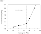
- the present inventors conducted the following experiment to examine the influence of cooling strain introduced during cooling as one of the factors other than the atmosphere that may adversely affect the iron loss properties in finish annealing.
- a steel material having an ingredient composition including C: 0.0021 mass%, Si: 3.7 mass%, Mn: 0.4 mass%, P: 0.01 mass%, S: 0.0016 mass%, Al: 0.6 mass%, Ti: 0.0014 mass%, Nb: 0.0010 mass%, O: 0.0025 mass%, and N: 0.0022 mass%, with the rest being Fe and unavoidable impurities was hot-rolled into a hot-rolled sheet having a sheet thickness of 1.8 mm.
- the hot-rolled sheet was subjected to hot-band annealing at 900°C for 30 seconds, pickled, and then cold-rolled into a cold-rolled sheet having a final sheet thickness of 0.25 mm.
- the average cooling rate from the soaking temperature of 1000°C to 900°C was varied within a range of 10 to 15°C/s.
- the reason for setting the temperature region in which the cooling rate was to be varied to the temperature region of 900°C or higher is that the cooling rate in this temperature region is considered to have a significant influence on cooling strain.
- a test specimen measuring 180 mm in length and 30 mm in width was cut out from each finish-annealed steel sheet, with the longitudinal direction in the L direction (rolling direction) and with the longitudinal direction in the C direction (perpendicular to rolling direction), and each iron loss W 10/400 was measured by the Epstein test.
- the results are shown in FIG. 7 as a relationship with the cooling rate. From this graph, it can be seen that controlling the average cooling rate in the temperature region of 900°C or higher to 15°C/s or less can prevent the increase in iron loss due to cooling strain.
- the slab used to produce the non-oriented electrical steel sheet of the present invention contain, as basic ingredients, Si: 2.8 to 6.5 mass%, Mn: 0.1 to 2.0 mass%, and Al: 0.3 to 2.0 mass%.
- the slab may contain at least one element selected from: P: 0.10 mass% or less, Sn: 0.005 to 0.20 mass%, Sb: 0.005 to 0.20 mass%, Ca: 0.0005 to 0.020 mass%, Mg: 0.0005 to 0.020 mass%, REM: 0.0005 to 0.020 mass%, Cr: 0.01 to 1.0 mass%, Co: 0.01 to 1.0 mass%, Ni: 0.01 to 1.0 mass%, Cu: 0.01 to 1.0 mass%, Mo: 0.001 to 0.1 mass%, and W: 0.001 to 0.1 mass%.
- C, S, N, Ti, Nb, and O are harmful elements that adversely affect the magnetic properties by forming carbonitrides to be precipitated, forming oxides, or forming sulfides. Therefore, it is preferable to limit these elements as follows: C: 0.0050 mass% or less, S: 0.0050 mass% or less, N: 0.0050 mass% or less, Ti: 0.0030 mass% or less, Nb: 0.0030 mass% or less, and O: 0.0050 mass% or less.
- the non-oriented electrical steel sheet of the present invention can be produced by a conventional known production process as follows: A steel material (slab) having the above-described ingredient composition is hot-rolled into a hot-rolled-sheet, and the hot-rolled sheet is subjected to hot-band annealing, if necessary, and then to one cold rolling or two or more cold rollings with intermediate annealing between each cold rolling to obtain a cold-rolled sheet having a final sheet thickness (product sheet thickness). Next, the cold-rolled sheet is subjected to finish annealing, and an insulation coating is formed thereon as necessary. In the following, the production method will be specifically described.
- the slab serving as the material of the non-oriented electrical steel sheet can be produced by melting steel having the above-described ingredient composition complying with the present invention by a commonly known refining process that uses a converter, an electric furnace, a vacuum degassing device, etc., and then performing a usual continuous casting method or an ingot-making blooming method, or can be formed into a thin cast slab with a thickness of 100 mm or less by a direct casting method.
- the slab is then hot-rolled into a hot-rolled sheet using a commonly known method and conditions.
- the slab is usually hot-rolled after being heated to a predetermined temperature in a heating furnace, but may be hot-rolled immediately after casting, without being reheated. In the case of a thin cast slab, it may be hot-rolled, or may be subjected to the subsequent steps without being hot rolling.
- the hot-rolled sheet having been hot-rolled is subjected to hot-band annealing, if necessary. It is preferable to perform the hot-band annealing under soaking conditions of 800 to 1 100°C for 180 seconds or less. When the soaking temperature is lower than 800°C, the effect of hot-band annealing is too small to sufficiently achieve a magnetic property improving effect. On the other hand, when the soaking temperature exceeds 1 100°C and the soaking time exceeds 180 seconds, the crystal grains are coarsened to facilitate brittle failure (sheet fracture) during cold rolling or impair productivity, which is disadvantageous in terms of the production cost. More preferable conditions are 850 to 1000°C for 60 seconds or less.
- the dew point of the atmosphere in the heating zone and the soaking zone in the hot-band annealing is 0°C or higher but not higher than 70°C.
- the dew point is lower than 0°C, an oxidized layer formed on the surface of the steel sheet during annealing is likely to be removed during pickling, so that nitriding may be promoted during finish annealing at a later stage and the magnetic properties may deteriorate.
- the dew point exceeds 70°C, conversely, an oxidized film that is difficult to remove by pickling is formed during annealing, which hinders the pickling efficiency or increases the load of cold rolling, thereby impairing productivity.
- the steel sheet after the hot rolling or hot-band annealing is then formed into a cold-rolled sheet with a final sheet thickness by one cold rolling or two or more cold rollings with intermediate annealing between each cold rolling. It is preferable that the final sheet thickness, i.e., the product sheet thickness, be 0.30 mm or less, from the viewpoint of reducing the iron loss.
- the cold-rolled sheet is subjected to finish annealing, which is the most important step in the present invention, and, if necessary, an insulation coating is applied thereto to obtain a product sheet.
- the soaking temperature in this finish annealing be within a range of 900 to 1200°C from the viewpoint of allowing the crystal grains to grow large and reducing the iron loss.
- the soaking temperature is lower than 900°C, the crystal grains do not grow sufficiently, while when the soaking temperature exceeds 1200°C, the crystal grains coarsen excessively or a disadvantage in terms of the heat energy cost is caused.
- a more preferable range is 1000 to 1100°C.
- the influence of the soaking temperature on the grain growth during finish annealing is substantially predominant, while the influence of the soaking time is minor. Therefore, the soaking time can be adjusted according to the length of the annealing furnace or the productivity taken into account.
- FIG. 8 is a view illustrating the finish annealing conditions of the present invention, with FIG. 8(a) at the top showing an example of the finish annealing facility having a horizontal continuous annealing furnace composed of a heating zone, a soaking zone, and a cooling zone, and FIG. 8(b) showing an example of the heat pattern in this finish annealing facility.
- the present invention is characterized in that the continuous annealing furnace shown in FIG. 8 is divided into the following three regions in the order in which a steel sheet is threaded: a "first region” where the furnace atmosphere temperature in the heating zone is lower than 900°C; a “second region” where the furnace atmosphere temperature in the heating zone, the soaking zone, and the cooling zone is 900°C or higher; and a "third region” where the furnace atmosphere temperature in the cooling zone is lower than 900°C, and in that the atmosphere in each region is controlled as described later.
- the furnace atmosphere of the continuous annealing furnace needs to be appropriately controlled from the viewpoint of preventing nitriding of the surface of the steel sheet that occurs during finish annealing.
- the furnace atmosphere in the second region i.e., the temperature region where the atmospheric temperature is 900°C or higher
- an atmosphere of one type of gas among N 2 , H 2 , and a rare gas or an atmosphere of a mixed gas of two or more types of these gases and to set the nitrogen content in the atmosphere to 30 vol% or less.
- the dew point of the atmosphere needs to be set to -40°C or lower.
- the nitrogen content is preferably 20 vol% or less, and the dew point is preferably -50°C or lower. Since the dew point of a gas that can be supplied as an industrial gas is about -60°C, the lower limit of the dew point is necessarily about -60°C.
- FIG. 8 (c) is a view showing the furnace atmospheres in the heat pattern of the finish annealing facility shown in FIGs. 8(a) and 8(b) at the top, as a comparison between the present invention and the prior art.
- the cooling rate from the soaking temperature to 900°C be controlled to 15°C/s or less.
- the cooling rate exceeds 15°C/s, the iron loss increases due to cooling strain.
- a more preferable cooling rate is 10°C/s or less.
- the first region located upstream of the second region i.e., the region where the furnace atmosphere temperature in the heating zone is lower than 900°C, be set to have an atmosphere having a nitrogen content of 80 vol% or more and a dew point of -40°C or lower.
- a more preferable nitrogen content is 90 vol% or more.
- the heating rate of the steel sheet in the first region of the finish annealing facility of the present invention be set to 100°C/s or more. This is because, when the heating rate is 100°C/s or more, the priority of recrystallization in the ⁇ 111 ⁇ orientation decreases, causing the orientation of recrystallized grains to become random, which has an enhancing effect on the magnetic flux density.
- a high heating rate that is too high raises concerns such as that, as the shape of the steel sheet cannot be corrected, the magnetic properties may deteriorate due to strain, or that heating unevenness may occur in the sheet width direction, resulting in larger variation in the iron loss value in the sheet width direction. Therefore, it is preferable that the upper limit of the heating rate be about 300°C/s.
- the heating rate of the steel sheet in the first region is set to 100°C/s or more
- the first region of the finish annealing facility be composed of a rapid heating zone and a heating zone in which the heating rate is lower than that in the rapid heating zone. It is preferable that rapid heating in the rapid heating zone be up to 700°C to 750°C, which is the Curie point of the steel sheet, and that thereafter the steel sheet be heated to 900°C at a lower rate than in the rapid heating zone.
- the atmosphere and the cooling rate are not particularly limited, and rapid cooling may be performed in a 100% nitrogen gas atmosphere, for example.
- the finish annealing facility of the present invention requires the annealing furnace to be divided into the first region, the second region, and the third region with the temperature of the furnace atmosphere of 900°C as the boundaries, where the gas composition and the dew point of the atmosphere need to be individually controlled in each region. Therefore, it is preferable that the annealing furnace be divided into a plurality of segments in the forward direction of the steel sheet as shown in FIG. 8 (a) and FIG. 9 (a) , and that the atmosphere be controllable for each segment.
- an H 2 gas has good heat transfer properties, including an H 2 gas in the atmospheric gas in the second region has the effect of reducing cooling unevenness in the sheet thickness direction during cooling and thereby reducing deterioration of the magnetic properties due to cooling strain.
- an H 2 gas is an explosive gas, it is preferable to prevent the gas from flowing into the first region or the third region where the temperature is lower than 900°C. From this viewpoint, it is preferable to provide an inter-zone seal (slit) between the first region and the second region and between the second region and the third region as shown in FIG. 8 (c) and FIG. 9 (c) .
- the gas composition and dew point of the atmosphere of each of the first region (the heating zone in which the atmospheric temperature is lower than 900°C), the second region (the heating zone, the soaking zone, and the cooling zone in which the atmospheric temperature is 900°C or higher), and the third region (the cooling zone in which the atmospheric temperature is lower than 900°C) of the annealing furnace were varied, as well as the soaking conditions (the soaking temperature and the soaking time) and the cooling rate from the soaking temperature to 900°C in the second region were varied.
- a test specimen was taken from each finish-annealed steel sheet thus obtained, and the content N s (mass%) of N present as AlN (N as AlN) in the 1/20-sheet-thickness layer and the content Nt (mass%) of N present as AlN (N as AlN) across the entire sheet thickness were analyzed by an electroextraction method. Further, a test specimen measuring 180 mm in length and 30 mm in width was cut out from each finish-annealed steel sheet, with the longitudinal direction in the L direction (rolling direction) and with the longitudinal direction in the C direction (perpendicular to rolling direction), and iron loss W 10/400 was measured by the Epstein test.
- the measurement results are also shown in Table 1.
- Example 2 Eight coils of steel sheets after cold rolling (cold-rolled sheets) produced in Example 1 were prepared, each having a sheet thickness of 0.25 mm and an ingredient composition containing Si: 3.7 mass%, Mn: 0.4 mass%, and Al: 0.6 mass%, with the rest being Fe and unavoidable impurities.
- four coils were threaded through the annealing facility shown in FIG. 8 and subjected to finish annealing under the same conditions as the steel sheets No. 1 to 4 in Table 1 of Example 1.
- the other four coils were threaded through the annealing facility shown in FIG. 9 in which the rapid heating zone is provided in the first region, and were subjected to finish annealing under the same conditions as the aforementioned four coils except that rapid heating was performed. Details of these finish annealing conditions are shown in Table 2.
- a test specimen was extracted from each finish-annealed steel sheet thus obtained, and the content N s (mass%) of N present as AlN (N as AlN) in the 1/20-sheet-thickness layer and the content Nt (mass%) of N present as AlN (N as AlN) across the entire sheet thickness were analyzed by an electroextraction method. Further, a test specimen measuring 180 mm in length and 30 mm in width, with the longitudinal direction in the L direction (rolling direction) and with the longitudinal direction in the C direction (perpendicular to rolling direction) was cut out from each finish-annealed steel sheet, and iron loss W 10/400 and magnetic flux density B 50 were measured by the Epstein test.
- the technology of the present invention can be applied to the production of not only iron core materials of drive motors of HEVs, EVs, and FCEVs but also iron core materials of motors of compressors of air conditioners, machine tools, high-speed generators, vacuum cleaners, and others.
Landscapes
- Chemical & Material Sciences (AREA)
- Engineering & Computer Science (AREA)
- Mechanical Engineering (AREA)
- Materials Engineering (AREA)
- Organic Chemistry (AREA)
- Metallurgy (AREA)
- Physics & Mathematics (AREA)
- Thermal Sciences (AREA)
- Crystallography & Structural Chemistry (AREA)
- Electromagnetism (AREA)
- General Engineering & Computer Science (AREA)
- Manufacturing & Machinery (AREA)
- Dispersion Chemistry (AREA)
- Power Engineering (AREA)
- Manufacturing Of Steel Electrode Plates (AREA)
- Soft Magnetic Materials (AREA)
- Heat Treatment Of Strip Materials And Filament Materials (AREA)
Applications Claiming Priority (2)
| Application Number | Priority Date | Filing Date | Title |
|---|---|---|---|
| JP2021179145 | 2021-11-02 | ||
| PCT/JP2022/038167 WO2023079922A1 (fr) | 2021-11-02 | 2022-10-13 | Installation de recuit de finition pour tôle d'acier électromagnétique, procédé de recuit de finition et procédé de production pour tôle d'acier électromagnétique, et tôle d'acier électromagnétique non orientée |
Publications (2)
| Publication Number | Publication Date |
|---|---|
| EP4414465A1 true EP4414465A1 (fr) | 2024-08-14 |
| EP4414465A4 EP4414465A4 (fr) | 2025-02-19 |
Family
ID=86241357
Family Applications (1)
| Application Number | Title | Priority Date | Filing Date |
|---|---|---|---|
| EP22889745.0A Pending EP4414465A4 (fr) | 2021-11-02 | 2022-10-13 | Installation de recuit de finition pour tôle d'acier électromagnétique, procédé de recuit de finition et procédé de production pour tôle d'acier électromagnétique, et tôle d'acier électromagnétique non orientée |
Country Status (8)
| Country | Link |
|---|---|
| US (1) | US20240410029A1 (fr) |
| EP (1) | EP4414465A4 (fr) |
| JP (1) | JP7529131B2 (fr) |
| KR (1) | KR20240089697A (fr) |
| CN (1) | CN118076756A (fr) |
| MX (1) | MX2024005270A (fr) |
| TW (1) | TWI850811B (fr) |
| WO (1) | WO2023079922A1 (fr) |
Families Citing this family (1)
| Publication number | Priority date | Publication date | Assignee | Title |
|---|---|---|---|---|
| KR20250093638A (ko) * | 2023-12-15 | 2025-06-25 | 주식회사 포스코 | 무방향성 전기강판 및 그 제조방법 |
Family Cites Families (12)
| Publication number | Priority date | Publication date | Assignee | Title |
|---|---|---|---|---|
| JPS60114521A (ja) * | 1983-11-24 | 1985-06-21 | Kawasaki Steel Corp | 珪素鋼板の連続仕上焼鈍炉の操業方法 |
| JP3331096B2 (ja) * | 1995-07-31 | 2002-10-07 | 川崎製鉄株式会社 | 磁束密度の高い方向性けい素鋼板の製造方法並びに脱炭焼鈍方法及び脱炭焼鈍設備 |
| JP4559879B2 (ja) * | 2005-03-07 | 2010-10-13 | 新日本製鐵株式会社 | 無方向性電磁鋼板およびその製造方法 |
| CN101287854B (zh) | 2005-10-14 | 2011-04-20 | 新日本制铁株式会社 | 含Si钢板的连续退火热浸镀方法以及连续退火热浸镀装置 |
| JP2008261033A (ja) * | 2007-04-13 | 2008-10-30 | Nippon Steel Corp | 方向性珪素鋼板の製造方法およびその連続脱炭・窒化焼鈍設備 |
| JP5854233B2 (ja) * | 2013-02-14 | 2016-02-09 | Jfeスチール株式会社 | 方向性電磁鋼板の製造方法 |
| CN103451399A (zh) * | 2013-08-29 | 2013-12-18 | 河北钢铁股份有限公司唐山分公司 | 生产冷轧无取向电工钢的退火工艺 |
| JP6738047B2 (ja) * | 2017-05-31 | 2020-08-12 | Jfeスチール株式会社 | 無方向性電磁鋼板とその製造方法 |
| EP3511430A1 (fr) * | 2018-01-12 | 2019-07-17 | SMS Group GmbH | Procédé de traitement thermique en continu d'une bande en acier et installation de revêtement par immersion en bain fondu d'une bande en acier |
| CN112930408B (zh) * | 2018-10-31 | 2023-01-17 | 杰富意钢铁株式会社 | 无取向性电磁钢板的制造方法 |
| KR102530719B1 (ko) * | 2018-12-27 | 2023-05-09 | 제이에프이 스틸 가부시키가이샤 | 무방향성 전기 강판 및 그 제조 방법 |
| CN112301192B (zh) * | 2020-10-13 | 2022-08-09 | 安阳钢铁股份有限公司 | 一种低碳含量冷轧无取向硅钢镀锌机组立式退火工艺 |
-
2022
- 2022-10-13 MX MX2024005270A patent/MX2024005270A/es unknown
- 2022-10-13 EP EP22889745.0A patent/EP4414465A4/fr active Pending
- 2022-10-13 JP JP2023501167A patent/JP7529131B2/ja active Active
- 2022-10-13 CN CN202280068093.4A patent/CN118076756A/zh active Pending
- 2022-10-13 US US18/699,366 patent/US20240410029A1/en active Pending
- 2022-10-13 WO PCT/JP2022/038167 patent/WO2023079922A1/fr not_active Ceased
- 2022-10-13 KR KR1020247015885A patent/KR20240089697A/ko active Pending
- 2022-10-21 TW TW111140099A patent/TWI850811B/zh active
Also Published As
| Publication number | Publication date |
|---|---|
| US20240410029A1 (en) | 2024-12-12 |
| WO2023079922A1 (fr) | 2023-05-11 |
| JP7529131B2 (ja) | 2024-08-06 |
| MX2024005270A (es) | 2024-05-17 |
| EP4414465A4 (fr) | 2025-02-19 |
| CN118076756A (zh) | 2024-05-24 |
| TWI850811B (zh) | 2024-08-01 |
| TW202319560A (zh) | 2023-05-16 |
| JPWO2023079922A1 (fr) | 2023-05-11 |
| KR20240089697A (ko) | 2024-06-20 |
Similar Documents
| Publication | Publication Date | Title |
|---|---|---|
| EP3243921B1 (fr) | Tôle d'acier électromagnétique à grains non orientés et son procédé de fabrication | |
| EP3404124B1 (fr) | Tôle d'acier électrique non orientée et son procédé de fabrication | |
| EP2025766B1 (fr) | Procédé permettant de produire une plaque d'acier magnétique à grains orientés présentant une densité de flux magnétique élevée | |
| EP2657355B1 (fr) | Procédé de fabrication d'une feuille d'acier électrique non-orienté | |
| US6444051B2 (en) | Method of manufacturing a grain-oriented electromagnetic steel sheet | |
| EP3992312A1 (fr) | Procédé de production de tôle d'acier électromagnétique à grains non orientés, procédé de production de noyau de moteur, et noyau de moteur | |
| EP2025767B1 (fr) | Procédé pour produire une tôle en acier électrique à grains orientés présentant une densité de flux magnétique élevée | |
| EP3633059A1 (fr) | Tôle d'acier électromagnétique non orienté et son procédé de production | |
| EP3904551A1 (fr) | Tôle d'acier électrique non orientée et son procédé de production | |
| EP3530770B1 (fr) | Tôle d'acier laminée à chaud destinée à la fabrication d'un tôle d'acier electrique, et procédé de fabrication de ladite tôle d'acier laminée à chaud | |
| EP4467669A1 (fr) | Procédé de fabrication de tôle d'acier laminée à chaud pour tôle d'acier électrique non orientée, procédé de fabrication de tôle d'acier électrique non orientée, et tôle d'acier laminée à chaud pour tôle d'acier électrique non orientée | |
| US7399369B2 (en) | Ultra-high magnetic flux density grain-oriented electrical steel sheet excellent in iron loss at a high magnetic flux density and film properties and method for producing the same | |
| EP4455345A1 (fr) | Tôle d'acier électrique à grains orientés, et son procédé de fabrication | |
| EP4414465A1 (fr) | Installation de recuit de finition pour tôle d'acier électromagnétique, procédé de recuit de finition et procédé de production pour tôle d'acier électromagnétique, et tôle d'acier électromagnétique non orientée | |
| EP1728885B1 (fr) | Procédé de fabrication d'une tôle d'acier électrique à grains orientés | |
| US20250263809A1 (en) | Grain oriented electrical steel sheet and method for manufacturing same | |
| EP3875613A1 (fr) | Procédé de fabrication de tôle d'acier électromagnétique à grains non orientés | |
| EP0798392A1 (fr) | Procédé de fabrication de tÔle d'acier électrique à grain orienté, possédant des caractéristiques magnétiques excellentes | |
| EP4596729A1 (fr) | Procédé de fabrication de tôle d'acier magnétique non orientée | |
| EP4729640A1 (fr) | Procédé de production d'une tôle d'acier électrique à grains orientés, et dispositif de chauffage par induction | |
| EP4450669A1 (fr) | Tôle d'acier électrique à grains orientés et son procédé de fabrication | |
| EP4575010A1 (fr) | Procédé de production d'une tôle d'acier électromagnétique à grains orientés, et dispositif de chauffage par induction | |
| KR20200066060A (ko) | 방향성 전기강판 및 그의 제조방법 | |
| EP4159335A1 (fr) | Procédé de production de feuille d'acier électromagnétique à grains orientés | |
| JPH0718334A (ja) | 優れた磁気特性を有する電磁鋼板の製造方法 |
Legal Events
| Date | Code | Title | Description |
|---|---|---|---|
| STAA | Information on the status of an ep patent application or granted ep patent |
Free format text: STATUS: THE INTERNATIONAL PUBLICATION HAS BEEN MADE |
|
| PUAI | Public reference made under article 153(3) epc to a published international application that has entered the european phase |
Free format text: ORIGINAL CODE: 0009012 |
|
| STAA | Information on the status of an ep patent application or granted ep patent |
Free format text: STATUS: REQUEST FOR EXAMINATION WAS MADE |
|
| 17P | Request for examination filed |
Effective date: 20240507 |
|
| AK | Designated contracting states |
Kind code of ref document: A1 Designated state(s): AL AT BE BG CH CY CZ DE DK EE ES FI FR GB GR HR HU IE IS IT LI LT LU LV MC ME MK MT NL NO PL PT RO RS SE SI SK SM TR |
|
| DAV | Request for validation of the european patent (deleted) | ||
| DAX | Request for extension of the european patent (deleted) | ||
| A4 | Supplementary search report drawn up and despatched |
Effective date: 20250121 |
|
| RIC1 | Information provided on ipc code assigned before grant |
Ipc: C22C 38/60 20060101ALI20250115BHEP Ipc: C22C 38/06 20060101ALI20250115BHEP Ipc: C22C 38/04 20060101ALI20250115BHEP Ipc: C22C 38/02 20060101ALI20250115BHEP Ipc: C22C 38/00 20060101ALI20250115BHEP Ipc: C21D 1/76 20060101ALI20250115BHEP Ipc: F27D 21/00 20060101ALI20250115BHEP Ipc: F27D 19/00 20060101ALI20250115BHEP Ipc: F27D 7/06 20060101ALI20250115BHEP Ipc: F27B 9/40 20060101ALI20250115BHEP Ipc: F27B 9/02 20060101ALI20250115BHEP Ipc: C21D 9/573 20060101ALI20250115BHEP Ipc: C21D 6/00 20060101ALI20250115BHEP Ipc: H01F 1/147 20060101ALI20250115BHEP Ipc: C21D 9/56 20060101ALI20250115BHEP Ipc: C21D 9/46 20060101ALI20250115BHEP Ipc: C21D 8/12 20060101AFI20250115BHEP |