EP4414508A1 - Procédé de détermination de remplacements d'éléments d'usure, système et machine correspondants - Google Patents
Procédé de détermination de remplacements d'éléments d'usure, système et machine correspondants Download PDFInfo
- Publication number
- EP4414508A1 EP4414508A1 EP23382121.4A EP23382121A EP4414508A1 EP 4414508 A1 EP4414508 A1 EP 4414508A1 EP 23382121 A EP23382121 A EP 23382121A EP 4414508 A1 EP4414508 A1 EP 4414508A1
- Authority
- EP
- European Patent Office
- Prior art keywords
- wear
- replacement
- determining
- elements
- assembly
- Prior art date
- Legal status (The legal status is an assumption and is not a legal conclusion. Google has not performed a legal analysis and makes no representation as to the accuracy of the status listed.)
- Withdrawn
Links
Images


Classifications
-
- E—FIXED CONSTRUCTIONS
- E02—HYDRAULIC ENGINEERING; FOUNDATIONS; SOIL SHIFTING
- E02F—DREDGING; SOIL-SHIFTING
- E02F9/00—Component parts of dredgers or soil-shifting machines, not restricted to one of the kinds covered by groups E02F3/00 - E02F7/00
- E02F9/28—Small metalwork for digging elements, e.g. teeth scraper bits
- E02F9/2808—Teeth
-
- E—FIXED CONSTRUCTIONS
- E02—HYDRAULIC ENGINEERING; FOUNDATIONS; SOIL SHIFTING
- E02F—DREDGING; SOIL-SHIFTING
- E02F9/00—Component parts of dredgers or soil-shifting machines, not restricted to one of the kinds covered by groups E02F3/00 - E02F7/00
- E02F9/26—Indicating devices
- E02F9/267—Diagnosing or detecting failure of vehicles
Definitions
- the invention is comprised in the field of earth-moving machines, particularly for excavators, loaders, dredging machines, or the like.
- the invention relates to a method for determining replacements of the wear elements of a wear assembly of an earth-moving machine.
- the invention also relates to a system for determining replacements of said wear elements, as well as the corresponding earth-moving machine.
- wear elements In the field of earth-moving machines, the state of the different wear elements used must be monitored, in particular, to enable determining when said any of said elements needs to be changed.
- These wear elements are commonly known as GET (ground engaging tool), with a common example being the teeth of an excavator, but also adaptors, front guards, side guards, wear caps, among others.
- a characterization of the soils on which work is being carried out can be useful, such that the wear level involved for the different wear elements due to abrasion can be determined.
- said characterization may allow anticipating the costs derived from the consumption of said elements, as well as supply needs in order to avoid having to stop working due to a lack of spare parts.
- the characteristics of each terrain may vary significantly from one excavation site to another.
- the objective of the invention is to provide a method for determining replacements of the type indicated above, which allows solving the aforementioned problems.
- wear assembly refers to a set of elements comprising at least one wear element and the support in which said at least one wear element is fixed, by way of non-exclusive example, an excavator shovel in which a plurality of teeth are fixed, although the invention can be applied to other types of wear elements, for example, those used in machines such as draglines, loaders, clamshells, shovels for cable buckets, and drills, among others possible examples.
- an earth-moving machine may comprise several wear assemblies.
- the control means carrying out the method can be the same for all the wear assemblies, independent for each one, or any intermediate situation in which there are several control means and each controls one or more wear assemblies.
- the method is, therefore, based on monitoring two main points.
- Second, the possibility of losing the wear elements (usually of the elements falling) is monitored. There are different proposals in the art for carrying out said monitoring of possible falls, for example, by means of proximity/presence sensors or using cameras monitoring the elements optically.
- the method of the invention uses a type of information that is already used in the art for other purposes (to detect losses of wear elements) and combines it with information relating to the state of the wear assembly, in order to thereby automatically determine whether the events, initially interpreted as possible losses, are actually replacements.
- the wear assembly when a wear element is to be replaced, the wear assembly is placed in a position in which replacement can be carried out, for example, by stopping the machine such that said machine and the wear assembly are not in motion (although it will be possible to keep the engine running) and placing the wear assembly within the operator's reach. If it is verified that, when there is an alert event, the wear assembly has been in a state suitable for replacement for a minimum time, it is determined that the alert event actually corresponds to replacement and not to a loss. Replacement is, therefore, automatically detected and it is not necessary for anyone to note that said replacement has been carried out. This information can then be used to automatically determine the work parameters of the previous wear element (for example, the element type, work hours, installation, and replacement date, among others) and this data can be used for the purposes discussed above.
- the work parameters of the previous wear element for example, the element type, work hours, installation, and replacement date, among others
- said monitoring of said wear assembly to detect said alert events is performed by fall detection means comprising at least one fall sensor for each of said wear elements.
- said at least one fall sensor comprises a presence sensor, for example, a sensor based on the detection of a magnetic field between the wear element and the support, can also be provided, said fall sensor being configured to detect whether said wear element corresponding to said presence sensor moves away from said wear assembly.
- said fall detection means comprise a plurality of sensors, for example, accelerometers and a magnetic presence sensor, can also be provided.
- said wear assembly comprises a bucket, for example, an excavator bucket, provided with said wear elements attached thereto and in which said state suitable for replacement comprises said bucket not being in motion, which usually means that the earth-moving machine is not in motion either, although it does not have to be completely stopped.
- the wear elements usually comprise excavator teeth, although they may also comprise tooth bars or adaptors assembled between the bucket and the teeth, as well as other interchangeable elements that wear off when used for earth-moving purposes.
- the guards which are placed between the adaptors or on the sides of the bucket, or the so-called wear caps, which are placed on the adaptors.
- a necessary condition to consider that the wear assembly comprised in the bucket to is in a state suitable for replacement is that the bucket itself must not be in motion. It is possible to foresee different alternatives on the way of determining the absence of movement of the bucket. For example, by means of a motion sensor arranged in the bucket itself or in the articulated assembly of the support thereof, by means of reading information relating to the situation of the earth-moving machine, by means of optical systems, such as cameras, by means of motion sensors arranged on the wear elements, etc., even combinations thereof.
- said state suitable for replacement comprises said bucket being positioned in a predefined range of angles, such that a necessary condition for determining that the bucket is in a state suitable for replacement is that the bucket is inclined in a position in which access to the wear elements is possible.
- This condition can be combined with the preceding condition of the bucket not being in motion.
- said predefined range of angles is between 15 and 45 degrees. Said angle is measured as an inclination with respect to the horizontal of the ground.
- the preferred lower limit is determined such that, for the specific type of wear assembly and machine, the wear element is kept in place without falling due to gravitational force.
- the preferred upper limit is determined by the difficulty an operator may experience when substituting the element, which tends to increase as the angle increases. In both cases, it will depend on the characteristics of the machine and the wear assembly.
- said predetermined time window is between 3 and 5 minutes such that, when the wear assembly is in a state suitable for replacement for at least 3-5 minutes, it is determined that the alert events correspond to replacement.
- a too short time may result in a false replacement determination, while a too long time would mean that those events that should actually be considered as replacements would still be considered as candidates to events of loss.
- the invention also relates to a system for determining replacements of wear elements of a wear assembly of an earth-moving machine, comprising monitoring means for monitoring said wear assembly configured to carry out the method described above.
- the invention also relates to an earth-moving machine comprising said system for determining replacements.
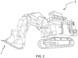
- a first embodiment of the invention relates to an earth-moving machine of the type shown in Figure 2 having a system for determining replacements of wear elements 2 of a wear assembly 1 such as that shown in Figure 1 and Figure 2 .
- the system includes the wear assembly 1 and monitoring means configured to carry out a method for determining replacements of said wear elements 2.
- said method for determining replacements of the wear elements 2 of the wear assembly 1 of the earth-moving machine 3 includes monitoring the wear assembly 1 to determine, over time, whether or not said wear assembly 1 is in a state suitable for replacement 200 of said wear elements 2.
- the first graph of Figure 3 shows an example of the time evolution of said monitoring, where said graph is a simplified representation in which a high level corresponds to an active state not suitable for replacement, while a low level corresponds to an inactive state suitable for replacement.
- the wear assembly 1 is an excavator bucket such as the one of Figure 1 with the wear elements 2 attached to said bucket.
- said bucket must not be in motion, which also means that the machine 3 is not in motion, although it is possible to keep the engine running.
- the bucket must also be positioned in a predefined range of angles of between 15 and 45 degrees.
- the monitoring of the wear assembly 1 to determine whether or not it is in a state suitable for replacement 200 is performed by means of accelerometers arranged inside each of the wear elements, or in the bucket itself, although other embodiments, for example, using operational information from a control unit of the earth-moving machine 3 itself, can be foreseen.
- the method also comprises monitoring the wear assembly 1 to detect whether alert events 100 take place, where each of said alert events 100 is a candidate to an event of loss of one of said wear elements 2.
- the three graphs in the lower portion of Figure 3 show simplified examples of the time evolution of the alert events associated with three of the wear elements 2. By way of example, the alert events are represented as peaks in the graphs.
- the monitoring of said wear assembly 1 to detect said alert events 100 is performed by fall detection means, with a fall sensor for each of the wear elements 2.
- the fall sensor of each wear element 2 is a presence sensor which detects whether its corresponding wear element 2 moves away from the wear assembly 1.
- the presence sensor is a magnetic Hall effect sensor arranged on the tooth bar, which detects the presence of a magnetic field generated by a magnet arranged inside the corresponding tooth.
- the method determines whether said wear assembly 1 has been in said state suitable for replacement 200 throughout at least an entire predetermined time window 300 up to the moment in which said alert event 100 has taken place.
- the predetermined time window 300 is 3 minutes, although other windows can be provided, among which those comprised between 3 and 5 minutes are preferred. If this is the case, the method determines that the alert event 100 is an event of replacement of the wear element 2 associated with said alert event 100. Therefore, it is determined that a replacement of said wear element 2 has taken place.
- the first graph shows when the wear assembly 1 is in the state suitable for replacement 200, while the other graphs correspond to the evolutions of three of the wear elements 2. These graphs are generated as illustrative and simplified graphs.
- the second graph of Figure 3 shows an alert event 100 which is determined when the wear assembly 1 is in the state suitable for replacement 200 and has been in said state for a time longer than said predetermined time window 300. Therefore, the alert event 100 of the second graph is determined as a replacement of the wear element 2 corresponding to said graph.
- the second wear element 2 does not exhibit any alert event 100, and thus, no replacement is determined either.
- the third wear element 2 exhibits an alert event 100.
- said event occurs when the wear assembly is not in a position suitable for replacement 200.
- the graph shows a possible time evolution corresponding to the fall of the wear element 2 when the machine 3 is performing earth-moving operations. Given that the alert event 100 takes place when the wear assembly 1 has not been in the state suitable for replacement 200 for the predetermined time window 300, it is not determined that a replacement has taken place either.
- the monitoring of said wear assembly 1 to detect the alert events 100 is performed by means of one or more cameras and an image analysis system allowing to identify the presence or absence of the wear elements 2.
Landscapes
- Engineering & Computer Science (AREA)
- Mining & Mineral Resources (AREA)
- Civil Engineering (AREA)
- General Engineering & Computer Science (AREA)
- Structural Engineering (AREA)
- Component Parts Of Construction Machinery (AREA)
- Length Measuring Devices With Unspecified Measuring Means (AREA)
- Testing Of Devices, Machine Parts, Or Other Structures Thereof (AREA)
- Sliding-Contact Bearings (AREA)
Priority Applications (6)
| Application Number | Priority Date | Filing Date | Title |
|---|---|---|---|
| EP23382121.4A EP4414508A1 (fr) | 2023-02-10 | 2023-02-10 | Procédé de détermination de remplacements d'éléments d'usure, système et machine correspondants |
| EP24702809.5A EP4662373A1 (fr) | 2023-02-10 | 2024-02-06 | Procédé de détermination de remplacements d'éléments d'usure, système et machine correspondants |
| AU2024218857A AU2024218857A1 (en) | 2023-02-10 | 2024-02-06 | Method for determining replacements of wear elements, corresponding system and machine |
| CN202480011895.0A CN120604014A (zh) | 2023-02-10 | 2024-02-06 | 用于确定磨损元件的更换的方法、对应的系统和机械 |
| PCT/EP2024/052915 WO2024165561A1 (fr) | 2023-02-10 | 2024-02-06 | Procédé de détermination de remplacements d'éléments d'usure, système et machine correspondants |
| CL2025002307A CL2025002307A1 (es) | 2023-02-10 | 2025-08-04 | Procedimiento para determinar reemplazos de unos elementos de desgaste, sistema y máquina correspondientes |
Applications Claiming Priority (1)
| Application Number | Priority Date | Filing Date | Title |
|---|---|---|---|
| EP23382121.4A EP4414508A1 (fr) | 2023-02-10 | 2023-02-10 | Procédé de détermination de remplacements d'éléments d'usure, système et machine correspondants |
Publications (1)
| Publication Number | Publication Date |
|---|---|
| EP4414508A1 true EP4414508A1 (fr) | 2024-08-14 |
Family
ID=85227017
Family Applications (2)
| Application Number | Title | Priority Date | Filing Date |
|---|---|---|---|
| EP23382121.4A Withdrawn EP4414508A1 (fr) | 2023-02-10 | 2023-02-10 | Procédé de détermination de remplacements d'éléments d'usure, système et machine correspondants |
| EP24702809.5A Pending EP4662373A1 (fr) | 2023-02-10 | 2024-02-06 | Procédé de détermination de remplacements d'éléments d'usure, système et machine correspondants |
Family Applications After (1)
| Application Number | Title | Priority Date | Filing Date |
|---|---|---|---|
| EP24702809.5A Pending EP4662373A1 (fr) | 2023-02-10 | 2024-02-06 | Procédé de détermination de remplacements d'éléments d'usure, système et machine correspondants |
Country Status (5)
| Country | Link |
|---|---|
| EP (2) | EP4414508A1 (fr) |
| CN (1) | CN120604014A (fr) |
| AU (1) | AU2024218857A1 (fr) |
| CL (1) | CL2025002307A1 (fr) |
| WO (1) | WO2024165561A1 (fr) |
Citations (1)
| Publication number | Priority date | Publication date | Assignee | Title |
|---|---|---|---|---|
| WO2015077735A1 (fr) * | 2013-11-25 | 2015-05-28 | Esco Corporation | Surveillance de pièces d'usure |
-
2023
- 2023-02-10 EP EP23382121.4A patent/EP4414508A1/fr not_active Withdrawn
-
2024
- 2024-02-06 EP EP24702809.5A patent/EP4662373A1/fr active Pending
- 2024-02-06 CN CN202480011895.0A patent/CN120604014A/zh active Pending
- 2024-02-06 WO PCT/EP2024/052915 patent/WO2024165561A1/fr not_active Ceased
- 2024-02-06 AU AU2024218857A patent/AU2024218857A1/en active Pending
-
2025
- 2025-08-04 CL CL2025002307A patent/CL2025002307A1/es unknown
Patent Citations (1)
| Publication number | Priority date | Publication date | Assignee | Title |
|---|---|---|---|---|
| WO2015077735A1 (fr) * | 2013-11-25 | 2015-05-28 | Esco Corporation | Surveillance de pièces d'usure |
Also Published As
| Publication number | Publication date |
|---|---|
| CL2025002307A1 (es) | 2025-11-14 |
| WO2024165561A1 (fr) | 2024-08-15 |
| CN120604014A (zh) | 2025-09-05 |
| AU2024218857A1 (en) | 2025-08-07 |
| EP4662373A1 (fr) | 2025-12-17 |
Similar Documents
| Publication | Publication Date | Title |
|---|---|---|
| AU2023202466B2 (en) | Wear part monitoring | |
| EP4414508A1 (fr) | Procédé de détermination de remplacements d'éléments d'usure, système et machine correspondants |
Legal Events
| Date | Code | Title | Description |
|---|---|---|---|
| PUAI | Public reference made under article 153(3) epc to a published international application that has entered the european phase |
Free format text: ORIGINAL CODE: 0009012 |
|
| STAA | Information on the status of an ep patent application or granted ep patent |
Free format text: STATUS: THE APPLICATION HAS BEEN PUBLISHED |
|
| AK | Designated contracting states |
Kind code of ref document: A1 Designated state(s): AL AT BE BG CH CY CZ DE DK EE ES FI FR GB GR HR HU IE IS IT LI LT LU LV MC ME MK MT NL NO PL PT RO RS SE SI SK SM TR |
|
| STAA | Information on the status of an ep patent application or granted ep patent |
Free format text: STATUS: THE APPLICATION IS DEEMED TO BE WITHDRAWN |
|
| 18D | Application deemed to be withdrawn |
Effective date: 20250215 |