EP4414583A2 - Ventileinheit mit verminderter reibung - Google Patents
Ventileinheit mit verminderter reibung Download PDFInfo
- Publication number
- EP4414583A2 EP4414583A2 EP23216925.0A EP23216925A EP4414583A2 EP 4414583 A2 EP4414583 A2 EP 4414583A2 EP 23216925 A EP23216925 A EP 23216925A EP 4414583 A2 EP4414583 A2 EP 4414583A2
- Authority
- EP
- European Patent Office
- Prior art keywords
- friction reducing
- shim
- valve assembly
- reducing material
- shims
- Prior art date
- Legal status (The legal status is an assumption and is not a legal conclusion. Google has not performed a legal analysis and makes no representation as to the accuracy of the status listed.)
- Pending
Links
- 239000000463 material Substances 0.000 claims abstract description 88
- 239000012530 fluid Substances 0.000 claims abstract description 72
- 230000035939 shock Effects 0.000 claims description 61
- 238000004381 surface treatment Methods 0.000 claims description 53
- 230000006835 compression Effects 0.000 claims description 33
- 238000007906 compression Methods 0.000 claims description 33
- 239000000725 suspension Substances 0.000 claims description 29
- 238000013016 damping Methods 0.000 claims description 25
- 239000010410 layer Substances 0.000 description 62
- 238000005336 cracking Methods 0.000 description 21
- 230000009467 reduction Effects 0.000 description 9
- 230000003068 static effect Effects 0.000 description 8
- 238000000576 coating method Methods 0.000 description 7
- 239000011248 coating agent Substances 0.000 description 6
- 238000000034 method Methods 0.000 description 6
- 230000000712 assembly Effects 0.000 description 5
- 238000000429 assembly Methods 0.000 description 5
- 239000007789 gas Substances 0.000 description 5
- 230000037361 pathway Effects 0.000 description 4
- 230000036316 preload Effects 0.000 description 4
- 230000004044 response Effects 0.000 description 4
- 239000006096 absorbing agent Substances 0.000 description 3
- 239000002356 single layer Substances 0.000 description 3
- IJGRMHOSHXDMSA-UHFFFAOYSA-N Atomic nitrogen Chemical compound N#N IJGRMHOSHXDMSA-UHFFFAOYSA-N 0.000 description 2
- 238000005411 Van der Waals force Methods 0.000 description 2
- 230000008859 change Effects 0.000 description 2
- 239000004810 polytetrafluoroethylene Substances 0.000 description 2
- 229920001343 polytetrafluoroethylene Polymers 0.000 description 2
- 230000008569 process Effects 0.000 description 2
- 238000007789 sealing Methods 0.000 description 2
- 238000004891 communication Methods 0.000 description 1
- 230000001419 dependent effect Effects 0.000 description 1
- 238000005516 engineering process Methods 0.000 description 1
- 238000007667 floating Methods 0.000 description 1
- 230000002452 interceptive effect Effects 0.000 description 1
- 229910052757 nitrogen Inorganic materials 0.000 description 1
- 230000000284 resting effect Effects 0.000 description 1
- 239000007787 solid Substances 0.000 description 1
- 238000011282 treatment Methods 0.000 description 1
- XLYOFNOQVPJJNP-UHFFFAOYSA-N water Substances O XLYOFNOQVPJJNP-UHFFFAOYSA-N 0.000 description 1
Images


Classifications
-
- F—MECHANICAL ENGINEERING; LIGHTING; HEATING; WEAPONS; BLASTING
- F16—ENGINEERING ELEMENTS AND UNITS; GENERAL MEASURES FOR PRODUCING AND MAINTAINING EFFECTIVE FUNCTIONING OF MACHINES OR INSTALLATIONS; THERMAL INSULATION IN GENERAL
- F16F—SPRINGS; SHOCK-ABSORBERS; MEANS FOR DAMPING VIBRATION
- F16F9/00—Springs, vibration-dampers, shock-absorbers, or similarly-constructed movement-dampers using a fluid or the equivalent as damping medium
- F16F9/32—Details
- F16F9/34—Special valve constructions; Shape or construction of throttling passages
- F16F9/348—Throttling passages in the form of annular discs or other plate-like elements which may or may not have a spring action, operating in opposite directions or singly, e.g. annular discs positioned on top of the valve or piston body
- F16F9/3482—Throttling passages in the form of annular discs or other plate-like elements which may or may not have a spring action, operating in opposite directions or singly, e.g. annular discs positioned on top of the valve or piston body the annular discs being incorporated within the valve or piston body
-
- F—MECHANICAL ENGINEERING; LIGHTING; HEATING; WEAPONS; BLASTING
- F16—ENGINEERING ELEMENTS AND UNITS; GENERAL MEASURES FOR PRODUCING AND MAINTAINING EFFECTIVE FUNCTIONING OF MACHINES OR INSTALLATIONS; THERMAL INSULATION IN GENERAL
- F16F—SPRINGS; SHOCK-ABSORBERS; MEANS FOR DAMPING VIBRATION
- F16F9/00—Springs, vibration-dampers, shock-absorbers, or similarly-constructed movement-dampers using a fluid or the equivalent as damping medium
- F16F9/32—Details
- F16F9/34—Special valve constructions; Shape or construction of throttling passages
- F16F9/348—Throttling passages in the form of annular discs or other plate-like elements which may or may not have a spring action, operating in opposite directions or singly, e.g. annular discs positioned on top of the valve or piston body
- F16F9/3484—Throttling passages in the form of annular discs or other plate-like elements which may or may not have a spring action, operating in opposite directions or singly, e.g. annular discs positioned on top of the valve or piston body characterised by features of the annular discs per se, singularly or in combination
Definitions
- Embodiments of the invention generally relate to a valve assembly. Some embodiments relate to a suspension inclusive device comprising the valve assembly. Some embodiments relate to a shock assembly comprising the valve assembly. Some embodiments relate to a vehicle comprising the valve assembly and/or the suspension inclusive device and/or the shock assembly.
- Shock assemblies are used in numerous different vehicles, devices, or the like and configurations to absorb some or all of a movement that is received at a first portion of a vehicle, device, or the like before it is transmitted to a second portion of the vehicle, device, or the like. For example, when a front wheel of a vehicle hits a rough spot, the encounter will cause an impact force on the wheel. By utilizing suspension components including one or more shock assemblies, the impact force can be significantly reduced or even absorbed completely by the suspension before it is transmitted to a suspended portion of the vehicle.
- Directional valving is often used to adjust and/or control a fluid flow through a fluid passage. For example, during a compression stroke, compression valving will allow the fluid to flow through a fluid passage. In contrast, during a rebound stroke, the compression valving will restrict the flow of fluid through the same fluid passage.
- One of the ways to implement directional valving is to use a shim stack to cover the fluid passage through a component.
- a predefined amount of pressure e.g., cracking pressure
- the fluid pressure will be applied through the fluid passage of the component and against the component facing side of the shim stack.
- the applied fluid pressure will be acting opposite the predefined cracking pressure of the shim stack. Accordingly, when the fluid pressure acting against the component facing side of the shim stack is greater than the predefined cracking pressure, the shim stack will (at least partially) deflect (or move away from the component facing side) causing the fluid pathway to open and allowing fluid to flow therethrough.
- the dynamic response of the components of the shock assembly are important to suspension performance. For example, if the valving responds quickly and accurately (e.g., cracks at the correct pressure, etc.) the suspension will perform as it is tuned to perform.
- a valve assembly may comprise a valve body.
- the valve body may comprise at least one fluid flow port therethrough.
- the valve assembly may comprise at least one shim pressed against said valve body, said at least one shim configured to control a fluid flow through said at least one fluid flow port.
- the valve assembly may comprise at least one friction reducing material disposed between said at least one shim and said valve body.
- the valve assembly may comprise a shim stack.
- the shim stack may comprise a plurality of shims.
- the shim stack may comprise a stick shim pressed against said valve body, said shim stack configured to control said fluid flow through said at least one fluid flow port with higher accuracy than a single shim.
- the at least one friction reducing material may be disposed between at least two of said plurality of shims of said shim stack.
- the at least one friction reducing material may be disposed between each of said plurality of shims of said shim stack.
- the at least one friction reducing material may be disposed between said plurality of shims of said shim stack in an alternating manner.
- valve assembly may comprise at least two friction reducing materials disposed between at least two of said plurality of shims of said shim stack.
- the at least two friction reducing materials may be disposed between each of said plurality of shims of said shim stack.
- the at least one friction reducing material may be a friction reducing surface treatment applied to said at least one shim.
- the friction reducing surface treatment may comprise one or more layers of a same type of said friction reducing surface treatment.
- the friction reducing surface treatment may comprise one or more layers of different types of friction reducing surface treatments.
- the at least one friction reducing material may be a stand-alone layer of friction reducing material.
- the stand-alone layer of friction reducing material may comprise one or more sub-layers of a same type of said friction reducing material.
- the stand-alone layer of friction reducing material may comprise one or more sub-layers of different types of friction reducing materials.
- the at least one friction reducing material may be a friction reducing surface treatment applied to said valve body.
- the shock assembly may comprise a damping chamber.
- the shock assembly may comprise a main piston coupled to a shaft and configured to divide said damping chamber into a compression side and a rebound side.
- the main piston may comprise a main piston body.
- the main piston may comprise at least one fluid pathway through said main piston body.
- the main piston may comprise at least one shim pressed against said main piston body, said at least one shim configured to meter a fluid flow through said at least one fluid pathway.
- the main piston may comprise at least one friction reducing material disposed between said at least one shim and said main piston body.
- the shock assembly may further comprise a shim stack.
- the shim stack may comprise a plurality of shims.
- the shim stack may comprise a stick shim pressed against said main piston body, said shim stack configured to meter the fluid flow through said at least one fluid pathway with higher accuracy than a single shim.
- the at least one friction reducing material may be disposed between at least two of said plurality of shims of said shim stack.
- the at least one friction reducing material may be disposed between each of said plurality of shims of said shim stack.
- the shock assembly may further comprise at least two friction reducing materials disposed between at least two of said plurality of shims of said shim stack.
- the shock assembly may further comprise at least two friction reducing materials disposed between each of said plurality of shims of said shim stack.
- the at least one friction reducing material may be a friction reducing surface treatment applied to said shim.
- the friction reducing surface treatment may comprise one or more layers of a same type of said friction reducing surface treatment.
- the friction reducing surface treatment may comprise one or more layers of different types of friction reducing surface treatments.
- the at least one friction reducing material may be a stand-alone layer of friction reducing material.
- said stand-alone layer of friction reducing material may comprise one or more sub-layers of a same type of said friction reducing material.
- the stand-alone layer of friction reducing material may comprise one or more sub-layers of different types of friction reducing materials.
- the at least one friction reducing material may be a friction reducing surface treatment applied to said main piston body.
- the valve assembly may comprise a valve body.
- the valve body may comprise at least one fluid flow port therethrough.
- the valve assembly may comprise a shim stack comprising a plurality of shims, said shim stack pressed against said valve body and configured to control a fluid flow through said at least one fluid flow port.
- the valve assembly may comprise at least one friction reducing material disposed between at least two shims of said shim stack. It may be that the at least one friction reducing material is not disposed between a shim and said valve body.
- the shock assembly may comprise a cylinder, said cylinder comprising a cylinder inner diameter.
- the shock assembly may comprise a piston shaft.
- the shock assembly may comprise a main damping piston, said main damping piston coupled to said piston shaft and configured for operation within said cylinder, said main damping piston configured to divide said cylinder into a compression side and a rebound side.
- the shock assembly may comprise a shim stack coupled to said main damping piston, wherein said shim stack is fit to meter fluid flow through said main damping piston.
- the shim stack may comprise a plurality of shims.
- the shim stack may comprise at least one layer of a friction reducing material disposed between said plurality of shims and/or a friction reducing surface treatment covering at least a portion of said plurality of shims.
- the suspension may comprise a damping valve, wherein said valve is configured to regulate a fluid flow.
- the damping valve may comprise at least one shim.
- the damping valve may further comprise at least one layer of a friction reducing material disposed next to the at least one shim.
- the suspension may comprise a damping valve, wherein said valve is configured to regulate a fluid flow.
- the damping valve may comprise at least one shim. At least a portion of the at least one shim may comprise a friction reducing surface treatment.
- the suspension damper may comprise a valve configured to regulate a fluid flow.
- the valve may comprise at least one shim.
- the valve may comprise at least one layer of a friction reducing material disposed next to the at least one shim. At least a portion of the at least one shim may comprise a friction reducing surface treatment.
- a valve assembly for a suspension.
- the valve assembly may comprise at least one shim configured to regulate a fluid flow.
- the valve assembly may comprise at least one layer of a friction reducing material disposed next to the at least one shim. At least a portion of the at least one shim may comprise a friction reducing surface treatment.
- a valve assembly for a suspension.
- the valve assembly may comprise at least one shim configured to regulate a fluid flow.
- the valve assembly may comprise at least one layer of a friction reducing material disposed next to the at least one shim.
- a valve assembly for a damper.
- the valve assembly may comprise at least one shim configured to regulate a fluid flow. At least a portion of the at least one shim may comprise a friction-reducing surface treatment.
- a suspension inclusive device comprising a valve assembly as set out in any of the statements above, or as described or as claimed anywhere herein.
- the suspension inclusive device may be an exoskeleton, a seat frame, a prosthetic, a suspended floor, a hood and/or trunk support for a vehicle, and a door closer, and the like.
- the shock assembly may comprise a damping chamber.
- the shock assembly may comprise a main piston coupled to a shaft and configured to divide said damping chamber into a compression side and a rebound side.
- the main piston may comprise a valve assembly as set out in any of the statements above, or as described or as claimed anywhere herein.
- a vehicle comprising: a valve assembly as set out in any of the statements above, or as described or as claimed anywhere herein; and/or a suspension inclusive device as set out in any of the statements above, or as described or as claimed anywhere herein; and/or a shock assembly as set out in any of the statements above, or as described or as claimed anywhere herein.
- latency refers to a time delay with respect to the dynamic response of a directional valve.
- the time delay could be at the opening and/or closing of the directional valve and/or between the operations thereof, e.g., the time between a first motion (e.g., closing) and a next motion (e.g., opening).
- latency is caused by van der Waals forces acting between a sealing shim and the edge of the port being sealed.
- hysteresis refers to inconsistencies in a damping curve.
- a shock assembly is selected and/or tuned to provide a specific and consistent damping curve.
- the repeated, specific, and reliable performance of a vehicle is dependent upon the damping curve being as accurate as possible.
- hysteresis can cause hysteresis such as, but not limited to, pressure induced body expansion, sticking between valves, friction between valves, friction between the glide rings/piston/body, gas compression, gas expansion, etc.
- latency in the opening of the shims can be caused by the van der Waals forces present between the sealing shim and the piston which can cause an increase in the cracking pressure of the shim stack.
- latency in the opening of the shims can be caused by frictional forces between static shims within a shim stack which will also increase the initial cracking pressure of the shim stack.
- Embodiments disclosed herein provide a novel method for reducing latency and/or hysteresis within the system by reducing the static and kinetic coefficients of friction between the shims in a shim stack.
- the reduced friction valve assembly described herein can be used with a number of different applications or systems that use one or more reduced friction valve shock assemblies.
- Applications include a vehicle such as, but not limited to a bicycle, an electric bike (e-bike), a hybrid bike, a scooter, a motorcycle, an ATV, a personal water craft (PWC), a vehicle with three or more wheels (e.g., a UTV such as a side-by-side, a car, truck, etc.), a snow machine, an aircraft, and the like.
- Additional examples include a suspension inclusive device such as, but not limited to, an exoskeleton, a seat frame, a prosthetic, a suspended floor, a hood and/or trunk support for a vehicle, a door closer, and the like. It should be noted that while embodiments are referred to as being part of a shock assembly, they are not limited to shock assemblies and may be applied to other embodiments, including non-shock assembly valving that utilizes shim stacks.
- one or more of the component of the reduced friction valve assembly may be active and/or semi-active.
- an active and/or semi-active component will have one or more electronically adjustable features controlled by a motive component such as a solenoid, stepper motor, electric motor, or the like.
- the active and/or semi-active component will receive an input command which will cause the motive component to move, modify, or otherwise change one or more aspects of one or more electronically adjustable features.
- the reduced friction valve assembly may be used in valves, such as base valves, compression valves, rebound valves, piston valves, and the like.
- valves such as base valves, compression valves, rebound valves, piston valves, and the like.
- Embodiments of different active valve suspension and components where the reduced friction valve assembly may be utilized are disclosed in U.S. Patents 8,838,335 ; 9,353,818 ; 9,682,604 ; 9,797,467 ; 10,036,443 ; 10,415,662 ; to which reference is specifically made .
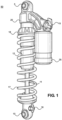
- shock assembly 50 is a coil-over shock assembly, such as, for example, a FOX 2.0 zero QS3-R shock assembly with a velocity-sensitive shimmed damping system, one or more coil-over springs 17, a spring preload adjuster 18, and a fluid reservoir 25.
- the shock assembly 50 is described as coil-over style shock assembly.
- the shock assembly 50 is a FOX load optimizing air technology (FLOAT) air shock assembly with a reservoir.
- FLOAT FOX load optimizing air technology
- an air shock assembly is a highperformance shock assembly that use air as springs, instead of one or more coil-over springs 17.
- the shock assembly 50 may be another type of shock assembly such as, but not limited to, a stand-alone fluid damper assembly, an air sprung fluid damper assembly, a monotube shock assembly, a twin-tube shock assembly, or the like.
- shock assembly 50 includes attachment features such as a chassis mount (e.g., upper eyelet 5) and a frame mount (e.g., lower eyelet 10) which allow shock assembly 50 to be coupled between the unsprung portion of the suspension (e.g., the components of the suspension affected by, or in contact with, the terrain) and the sprung portion.
- a chassis mount e.g., upper eyelet 5
- a frame mount e.g., lower eyelet 10
- eyelets are shown, it should be appreciated that the mounting systems may be bolts, welds, or the like, the use of eyelets is provided as one embodiment and for purposes of clarity.
- Shock assembly 50 of Figure 1 also includes body 12, a body cap 20, and a fluid reservoir 25 fluidly coupled with the body 12.
- fluid reservoir 25 is a remote fluid reservoir.
- fluid reservoir 25 will include an internal floating piston (IFP) fluidly dividing the external reservoir into a working fluid side and a pressurized gas side. Where the pressurized gas side is able to compress to compensate for the shaft displaced fluid that enters the reservoir.
- Shaft displaced fluid refers to the fluid that is displaced from the damper chamber due to a reduction in available fluid volume within the damper chamber due to the additional volume of shaft 11 as it moves into a main chamber within body 12 during a compression stroke. Fluid communication between the main chamber and the fluid reservoir 25 may be via a flow channel and include additional valving. Additional detail and description of an external reservoir is described in U.S. Pat. No. 7,374,028 to which reference is made.
- fluid reservoir 25 is an external reservoir.
- the fluid reservoir 25 is defined by a base valve within the main chamber.
- an IFP is also located within the fluid reservoir 25 portion of the main chamber and again, is used to compensate for the changes in available volume of the main chamber due to shaft displaced volume.
- shock absorber assembly see, as an example, U.S. Patent 10,576,803 to which reference is made.
- position-sensitive shock absorber/damper see, as an example, U.S. Patent 6,296,092 to which reference is made.
- shock assembly 50 optionally includes a compression adjuster 35 and/or a rebound adjuster 16.
- a compression adjuster 35 for additional detail and description of adjustable compression and/or rebound damping, preload, crossover, bottom-out, and the like for a shock absorber/damper, see, as an example, U.S. Patent 10,036,443 , to which reference is made.
- FIG. 2 a cross-section view of shock assembly 50 with the reduced friction valve assembly of Figure 1 is shown in accordance with an embodiment.
- FIG. 2 For purpose of clarity, in the discussion of Figure 2 , all of the components described in Figure 1 are incorporated by reference in their entirety.
- Shock assembly 50 of Figure 2 includes a chamber 210 within body 12, and a piston 223 coupled with the shaft 11.
- the piston 223 and a portion of shaft 11 are located within chamber 210 and divide chamber 210 into a compression side 226 and a rebound side 246.
- piston 223 may be vented or solid and internal or external bypasses may also be present.
- Fluid reservoir 25 includes a reservoir chamber 225 that is divided by an IFP 227.
- one side (e.g., side 281) of the IFP 227 divided reservoir chamber 225 is filled with a pressurized gas (e.g., nitrogen, or the like) and the other side (e.g., side 282) of reservoir chamber 225 contains working fluid.
- Reservoir chamber 225 is fluidly coupled with chamber 210 of body 12 via flow path 244 through body cap 20.
- the optional compression adjuster 15 valving for controlling the compression flow rate from the chamber 210 to the reservoir chamber 225 is coupled with body cap 20 and resides within a portion of flow path 244.
- Coil-over spring 17 provides an expansive (e.g., spring) force on the shock assembly 50.
- the resting sag length of the mounted shock assembly 50 is maintained in compression by the weight of the body it is suspending (e.g., the sprung portion of the vehicle), and in expansion by the "spring” force produced by the expansion component (e.g., coil-over spring 17).
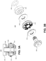
- Figure 3A a cross-section view of a piston 223 with a reduced friction valve assembly is shown in accordance with an embodiment.
- Figure 3B is an exploded view of the piston 223 with a reduced friction valve assembly of Figure 3A .
- piston 223 includes a bolt 305, rebound valving assembly (e.g., rebound shim stack 310), piston body 315 (with ports therethrough), compression valving assembly (e.g., compression shim stack 320), top out plate 325, and an O-ring 330.
- rebound valving assembly e.g., rebound shim stack 310
- piston body 315 with ports therethrough
- compression valving assembly e.g., compression shim stack 320
- top out plate 325 e.g., top out plate 325
- O-ring 330 e.g., O-ring 330
- compression shim stack 320 and rebound shim stack 310 each include a plurality of shim stacks.
- the cracking pressure is used to set and/or control the compression and rebound damping characteristics of piston 223.
- the compression shim stack 320 and rebound shim stack 310 are built with the same components and geometries and provide an equivalent cracking pressure.
- the compression shim stack 320 and rebound shim stack 310 are built with different components and/or geometries to provide a valve with a different compression side and rebound side cracking pressures.
- the components of the valve assemblies are selected based on the desired cracking pressure values.
- a ball park cracking pressure is achieved by selecting and utilizing shims with certain characteristics to build each shim stack.
- varying the diameter of the footprint of the shimstack, selecting the appropriate outer diameter (OD) or thickness of the stick shim 546 (e.g., the innermost shim or deload shim), and the like will allow the shim stack to be built within the ballpark cracking pressure.
- the cracking pressure is more finely tuned by adjusting the location and interactive portion of the outlet cover with respect to the outlet cover shimstack to establish the flat plate area of the shim that can be contacted by the working fluid and thus, the fluid pressure acting on the shimstack.
- the force applied by top out plate 325 on rebound shim stack 310 can be adjusted independently from the force applied by bolt 305 on compression shim stack 320 to provide a different cracking pressure between the rebound shim stack 310 and the compression shim stack 320.
- a compression adjuster 15 adjusts the compression (and or rebound) by changing the fluid flow through one or more bleed holes in a compression chamber (or base valve, etc.) to soften or stiffen the suspension.
- the reduced friction valve assembly is used in a bottom out valve, or the like. Additional information regarding bottom-out features and control can be found in U.S. Patent 11,131,361 to which reference is made.
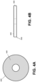
- Figure 4B is a side view of a shim 400, according to one embodiment.
- the shims 400 are circular in shape.
- the shims 400 may have one, or a plurality of different geometric shapes such as ovals and the like.
- the shims 400 are flat.
- one or more of the shims 400 are bent, formed like a bowl, or the like.
- the shape and geometry of the shim 400 can be modified for purposes such as fitment, location within the shim stack, to induce a desired preload, and the like.
- the shape of one, some, or all of the shims 400 in a shim stack could be uniform or could be non-uniform.
- static friction can occur between the shims 400 in the shim stack 510, between the stick shim 546 and the surface of the valve body (e.g., piston body 315), and/or between the shim 400 and other components to which it comes in contact.
- the force or pressure that builds up to the opening of the shim stack 510 can cause additional friction and shear force along an axis (such as the left to right axis of at least Figure 4B of the shims 400.
- an axis such as the left to right axis of at least Figure 4B of the shims 400.
- the stick shim 546 is lifted to allow fluid flow it will exert an inward force in the axial direction on the shim 400 adjacent to it.
- that shim 400 will lift and exert an inward force in the axial direction on the next shim 400, and so forth.
- This force inward force in the axial direction will increase the friction between the shims 400, which can cause latency and hysteresis.
- a friction reducing surface treatment 440 and/or a layer 540 of a friction reducing material discussed in Figures 5-7
- the shear force and frictional force both static and kinetic
- a portion of shim 400 is treated with at least one friction reducing surface treatment 440.
- one side of shim 400 is treated with at least one friction reducing surface treatment 440.
- both sides of shim 400 are treated with at least one friction reducing surface treatment 440.
- the friction reduction surface treatment 440 has a lower static and kinetic friction coefficient than the plain face of the shim 400.
- the friction reduction surface treatment 440 is PTFE, or the like.
- the friction reducing surface treatment 440 is used to reduce a coefficient of friction between shim 400 any other surface that might contact the shim 400 (e.g., another shim 400, a valve face, or the like).
- the friction reducing surface treatment 440 could be used on a side of the stick shim 546 pressed against the face of the valve body (e.g., piston body 315, or another valve type such as a base valve, or other directional controlled valve).
- the face of the valve body receives a layer of friction reduction surface treatment 440.
- the friction reduction surface treatment 440 is a film applied to the surface of the shim 400.
- the friction reducing surface treatment 440 can be applied as a coating, a surface finish, or a similar friction reducing technique.
- the friction reduction surface treatment 440 is a splatter coat type layer applied to the surface of the shim 400.
- the friction reduction surface treatment 440 is a nano-coat applied to the surface of the shim 400.
- the thickness of the coating of the friction reducing surface treatment 440 will vary based on the number of layers or type of coating. For example, the coating can be as thin as a few dozen atoms or much thicker.
- the friction reducing surface treatment 440 is made of one or several layers of the same friction reducing coating or several layers of different friction reducing coatings. In one embodiment, the friction reducing surface treatment 440 is a combination of a surface finish and at least one coating.
- the friction reducing surface treatment 440 is done to only a portion of the available surface of shim 400.
- a shim stack (such as shim stack 510) could include a shim 400 having a friction-reducing surface treatment 440 being disposed between shims 400 that do not have the same treatment.
- a shim 400 having a friction-reducing surface treatment 440 could be disposed between the stick shim 546 and its adjacent shim 400.
- shims 400 having a friction-reducing surface treatment are disposed between untreated shims 400 in a shim stack in an alternating manner.
- a cross-section view of a shim stack 510 with alternating layers 540 of a friction reducing material and shims 400 is shown in accordance with one embodiment.
- the layer 540 of a friction reducing material is a stand-alone layer.
- the layer 540 of friction reducing material (similar to the friction reduction surface treatment 440) has a lower static and kinetic friction coefficient than the plain face of the shim 400.
- the layer 540 of a friction reducing material is PTFE, or the like.
- the layer 540 of a friction reducing material is used to reduce a coefficient of friction between shim 400 any other surface that might contact the shim 400 (e.g., another shim 400, a valve face, or the like).
- the layer 540 of friction reducing material is disposed between the stick shim 546 and the face of the valve body (e.g., piston body 315, or another valve type such as a base valve, or other directional controlled valve).
- each layer 540 of the friction reducing material is made of one or several sublayers of friction reducing material. In one embodiment, the layer 540 of friction reducing material is made of several sublayers of different friction reducing materials. In another embodiment, the layer 540 of friction reducing material is made of several sublayers of similar friction reducing materials.
- a friction reducing surface treatment 440 is applied to one or more shims, e.g., the shims 400 are treated with a friction reducing surface treatment.
- a friction reducing surface treatment 440 is also applied to one or more shims 400.
- some of the shims 400 will have a layer 540 of friction reducing material therebetween, while other of the shims 400 will have a friction reducing surface treatment 440 and at least one layer 540 of a friction reducing material disposed between the shims 400 in an alternating manner.
- At least one side of at least one shim 400 has a rough surface finish in order to better engage with the friction reducing surface treatment 440 and/or the layer 540 of friction reducing material.
- FIG. 6 a cross-section view of a shim stack 610 with differing layers 540 of a friction reducing material between shims 400 is shown in accordance with one embodiment.
- the shim stack 610 there may be two layers 540u and 540l of a friction reducing material between one, some, or all of the shims 400.
- the friction reducing surface treatment 440 is applied to both shim facing sides of one, some, or all of shims 400.
- one or more layers 540 of friction reducing material is deployed between one, some, or all of the shims 400 in addition to the friction reducing surface treatment 440 being applied to one, some, or all of the shims 400.
- At least one layer 540 of the friction reducing material and the friction reducing surface treatment 440 are used on a subset of shims 400/shim interfaces to address a dominant source of friction.
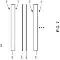
- FIG. 7 a cross-section view of two shims 400 and 400 and two layers 540u and 540l of a friction reducing material in between the shims 400 and 400 is shown in accordance with an embodiment.
- each of shims 400 and 400 have a first side 710 and a second side 705.
- the first side 710 is a rough side. The rough surface on the first side 710 allows for the shim to grip the adjacent layer of the friction reducing material (e.g., layer 540u or layer 540l).
- using two layers 540u and 540l of friction reducing material will allow the layers 540u and 540l to slide against each other while the shims 400 and 400 hold onto the opposite sides of layers 540u and 5401. In so doing, the static and kinetic coefficients of friction are further reduced as compared to an embodiment with a single layer of friction reducing material between two shims 400 and 400. Moreover, as the layers 540u and 540l of the friction reducing material do not separate, any van der Waal forces between the two is acceptable and will not affect latency or hysteresis.
- the second side 705 of the shim can be either rough or smooth.
- the second side 705 of the shim is rough if it is the bottom side of the stick shim 546 that will be in contact with the piston face.
- the second side 705 is smooth if it is not next to a layer of friction reducing material and is not the bottom side of the stick shim 546.
- the shims are preloaded by an external force.
- the shims 400 are bent, or formed like a bowl, to induce a preload.
- the shims in question are coupled to a base valve rather than a damping piston.
Landscapes
- Engineering & Computer Science (AREA)
- General Engineering & Computer Science (AREA)
- Mechanical Engineering (AREA)
- Multiple-Way Valves (AREA)
- Fluid-Damping Devices (AREA)
Applications Claiming Priority (2)
| Application Number | Priority Date | Filing Date | Title |
|---|---|---|---|
| US202263432652P | 2022-12-14 | 2022-12-14 | |
| US18/537,568 US20240229890A1 (en) | 2022-12-14 | 2023-12-12 | Reduced friction valve assembly |
Publications (2)
| Publication Number | Publication Date |
|---|---|
| EP4414583A2 true EP4414583A2 (de) | 2024-08-14 |
| EP4414583A3 EP4414583A3 (de) | 2024-11-06 |
Family
ID=89223074
Family Applications (1)
| Application Number | Title | Priority Date | Filing Date |
|---|---|---|---|
| EP23216925.0A Pending EP4414583A3 (de) | 2022-12-14 | 2023-12-14 | Ventileinheit mit verminderter reibung |
Country Status (2)
| Country | Link |
|---|---|
| EP (1) | EP4414583A3 (de) |
| TW (1) | TW202430788A (de) |
Citations (9)
| Publication number | Priority date | Publication date | Assignee | Title |
|---|---|---|---|---|
| US6296092B1 (en) | 1998-10-28 | 2001-10-02 | Fox Factory, Inc. | Position-sensitive shock absorber |
| US7374028B2 (en) | 2003-07-08 | 2008-05-20 | Fox Factory, Inc. | Damper with pressure-sensitive compression damping |
| US8838335B2 (en) | 2011-09-12 | 2014-09-16 | Fox Factory, Inc. | Methods and apparatus for suspension set up |
| US9353818B2 (en) | 2009-01-07 | 2016-05-31 | Fox Factory, Inc. | Remotely operated bypass for a suspension damper |
| US9682604B2 (en) | 2009-03-19 | 2017-06-20 | Fox Factory, Inc. | Methods and apparatus for selective spring pre-load adjustment |
| US9797467B2 (en) | 2008-03-19 | 2017-10-24 | Fox Factory, Inc. | Methods and apparatus for combined variable damping and variable spring rate suspension |
| US10036443B2 (en) | 2009-03-19 | 2018-07-31 | Fox Factory, Inc. | Methods and apparatus for suspension adjustment |
| US10576803B2 (en) | 2014-09-17 | 2020-03-03 | Fox Factory, Inc. | Shock absorber |
| US11131361B2 (en) | 2008-05-09 | 2021-09-28 | Fox Factory, Inc. | Methods and apparatus for position sensitive suspension damping |
Family Cites Families (4)
| Publication number | Priority date | Publication date | Assignee | Title |
|---|---|---|---|---|
| FR2265022B1 (de) * | 1974-03-21 | 1977-08-19 | Duveau Francois | |
| DE19738617C2 (de) * | 1997-09-04 | 2003-03-13 | Daimler Chrysler Ag | Stoßdämpfer für Kraftfahrzeuge |
| JP2009036261A (ja) * | 2007-07-31 | 2009-02-19 | Kayaba Ind Co Ltd | 積層リーフバルブ |
| JP2015161320A (ja) * | 2014-02-26 | 2015-09-07 | 株式会社ショーワ | 油圧緩衝器 |
-
2023
- 2023-12-13 TW TW112148532A patent/TW202430788A/zh unknown
- 2023-12-14 EP EP23216925.0A patent/EP4414583A3/de active Pending
Patent Citations (10)
| Publication number | Priority date | Publication date | Assignee | Title |
|---|---|---|---|---|
| US6296092B1 (en) | 1998-10-28 | 2001-10-02 | Fox Factory, Inc. | Position-sensitive shock absorber |
| US7374028B2 (en) | 2003-07-08 | 2008-05-20 | Fox Factory, Inc. | Damper with pressure-sensitive compression damping |
| US9797467B2 (en) | 2008-03-19 | 2017-10-24 | Fox Factory, Inc. | Methods and apparatus for combined variable damping and variable spring rate suspension |
| US11131361B2 (en) | 2008-05-09 | 2021-09-28 | Fox Factory, Inc. | Methods and apparatus for position sensitive suspension damping |
| US9353818B2 (en) | 2009-01-07 | 2016-05-31 | Fox Factory, Inc. | Remotely operated bypass for a suspension damper |
| US10415662B2 (en) | 2009-01-07 | 2019-09-17 | Fox Factory, Inc. | Remotely operated bypass for a suspension damper |
| US9682604B2 (en) | 2009-03-19 | 2017-06-20 | Fox Factory, Inc. | Methods and apparatus for selective spring pre-load adjustment |
| US10036443B2 (en) | 2009-03-19 | 2018-07-31 | Fox Factory, Inc. | Methods and apparatus for suspension adjustment |
| US8838335B2 (en) | 2011-09-12 | 2014-09-16 | Fox Factory, Inc. | Methods and apparatus for suspension set up |
| US10576803B2 (en) | 2014-09-17 | 2020-03-03 | Fox Factory, Inc. | Shock absorber |
Also Published As
| Publication number | Publication date |
|---|---|
| TW202430788A (zh) | 2024-08-01 |
| EP4414583A3 (de) | 2024-11-06 |
Similar Documents
| Publication | Publication Date | Title |
|---|---|---|
| JP6502547B2 (ja) | ショックアブソーバ | |
| JP5350372B2 (ja) | ショックアブソーバ | |
| CN1965174B (zh) | 电控频率相依型阻尼 | |
| US7886882B2 (en) | Pneumatic spring damper unit | |
| EP2333373B1 (de) | Einzelrohrkolbenventilsystem | |
| JP4143782B2 (ja) | エアサスペンション装置 | |
| US6332622B1 (en) | Suspension apparatus having two interconnected shock absorbers | |
| EP2153082B1 (de) | Aufhängungssysteme | |
| JP5909557B2 (ja) | サスペンション装置 | |
| EP1148268A2 (de) | Scheibenventil mit veränderlichen Durchlassöffnungen | |
| US20240286452A1 (en) | Shuttle valve shock assembly | |
| WO2005036014A2 (en) | Shock absorber apparatus | |
| JP2012517925A (ja) | アクティブ懸架システム及び該アクティブ懸架システムに使用する流体圧駆動ラム | |
| CN1867788A (zh) | 减振器分级阀系统 | |
| US6382372B1 (en) | Ported disc variable bleed orifice | |
| US12522039B2 (en) | Suspension system with proportional pressure accumulator | |
| EP1167810B1 (de) | Stossdämpfer mit Anpassungsfähigkeit bei niedriger Geschwindigkeit, umfassend eine Scheibe mit Durchflussöffnungen | |
| US6644445B2 (en) | Floating port blocker | |
| US20240229890A1 (en) | Reduced friction valve assembly | |
| US10995815B2 (en) | Damper with flexible floating disc | |
| US20250303811A1 (en) | Velocity dependent air spring | |
| EP4148297A1 (de) | Bypassöffnungskolben | |
| TW202430788A (zh) | 減摩閥組件 | |
| KR20240150135A (ko) | 컨택 쇼크를 저감할 수 있는 차량 댐퍼 제어방법 및 제어시스템 | |
| US20060231358A1 (en) | Pre-load ring for shock absorber |
Legal Events
| Date | Code | Title | Description |
|---|---|---|---|
| PUAI | Public reference made under article 153(3) epc to a published international application that has entered the european phase |
Free format text: ORIGINAL CODE: 0009012 |
|
| STAA | Information on the status of an ep patent application or granted ep patent |
Free format text: STATUS: THE APPLICATION HAS BEEN PUBLISHED |
|
| AK | Designated contracting states |
Kind code of ref document: A2 Designated state(s): AL AT BE BG CH CY CZ DE DK EE ES FI FR GB GR HR HU IE IS IT LI LT LU LV MC ME MK MT NL NO PL PT RO RS SE SI SK SM TR |
|
| PUAL | Search report despatched |
Free format text: ORIGINAL CODE: 0009013 |
|
| AK | Designated contracting states |
Kind code of ref document: A3 Designated state(s): AL AT BE BG CH CY CZ DE DK EE ES FI FR GB GR HR HU IE IS IT LI LT LU LV MC ME MK MT NL NO PL PT RO RS SE SI SK SM TR |
|
| RIC1 | Information provided on ipc code assigned before grant |
Ipc: F16F 9/348 20060101ALI20241001BHEP Ipc: F16F 9/34 20060101AFI20241001BHEP |
|
| STAA | Information on the status of an ep patent application or granted ep patent |
Free format text: STATUS: REQUEST FOR EXAMINATION WAS MADE |
|
| 17P | Request for examination filed |
Effective date: 20250328 |