EP4414616A1 - Tiroir pour la cuisson à la vapeur - Google Patents
Tiroir pour la cuisson à la vapeur Download PDFInfo
- Publication number
- EP4414616A1 EP4414616A1 EP24152326.5A EP24152326A EP4414616A1 EP 4414616 A1 EP4414616 A1 EP 4414616A1 EP 24152326 A EP24152326 A EP 24152326A EP 4414616 A1 EP4414616 A1 EP 4414616A1
- Authority
- EP
- European Patent Office
- Prior art keywords
- steam cooking
- drawer
- steam
- lid
- cooking drawer
- Prior art date
- Legal status (The legal status is an assumption and is not a legal conclusion. Google has not performed a legal analysis and makes no representation as to the accuracy of the status listed.)
- Pending
Links
- 238000010411 cooking Methods 0.000 claims abstract description 105
- 230000000630 rising effect Effects 0.000 description 16
- 238000000034 method Methods 0.000 description 6
- 238000010276 construction Methods 0.000 description 5
- 238000009434 installation Methods 0.000 description 3
- 239000000463 material Substances 0.000 description 3
- XLYOFNOQVPJJNP-UHFFFAOYSA-N water Chemical compound O XLYOFNOQVPJJNP-UHFFFAOYSA-N 0.000 description 3
- 239000003570 air Substances 0.000 description 2
- 230000005484 gravity Effects 0.000 description 2
- 239000012080 ambient air Substances 0.000 description 1
- 238000009835 boiling Methods 0.000 description 1
- 238000005253 cladding Methods 0.000 description 1
- 239000004020 conductor Substances 0.000 description 1
- 238000001816 cooling Methods 0.000 description 1
- 230000003111 delayed effect Effects 0.000 description 1
- 238000011161 development Methods 0.000 description 1
- 230000018109 developmental process Effects 0.000 description 1
- 230000000694 effects Effects 0.000 description 1
- 238000003825 pressing Methods 0.000 description 1
- 230000000007 visual effect Effects 0.000 description 1
Images

Classifications
-
- F—MECHANICAL ENGINEERING; LIGHTING; HEATING; WEAPONS; BLASTING
- F24—HEATING; RANGES; VENTILATING
- F24C—DOMESTIC STOVES OR RANGES ; DETAILS OF DOMESTIC STOVES OR RANGES, OF GENERAL APPLICATION
- F24C7/00—Stoves or ranges heated by electric energy
- F24C7/08—Arrangement or mounting of control or safety devices
- F24C7/082—Arrangement or mounting of control or safety devices on ranges, e.g. control panels, illumination
- F24C7/085—Arrangement or mounting of control or safety devices on ranges, e.g. control panels, illumination on baking ovens
-
- F—MECHANICAL ENGINEERING; LIGHTING; HEATING; WEAPONS; BLASTING
- F24—HEATING; RANGES; VENTILATING
- F24C—DOMESTIC STOVES OR RANGES ; DETAILS OF DOMESTIC STOVES OR RANGES, OF GENERAL APPLICATION
- F24C15/00—Details
- F24C15/30—Arrangements for mounting stoves or ranges in particular locations
-
- F—MECHANICAL ENGINEERING; LIGHTING; HEATING; WEAPONS; BLASTING
- F24—HEATING; RANGES; VENTILATING
- F24C—DOMESTIC STOVES OR RANGES ; DETAILS OF DOMESTIC STOVES OR RANGES, OF GENERAL APPLICATION
- F24C15/00—Details
- F24C15/32—Arrangements of ducts for hot gases, e.g. in or around baking ovens
- F24C15/322—Arrangements of ducts for hot gases, e.g. in or around baking ovens with forced circulation
- F24C15/327—Arrangements of ducts for hot gases, e.g. in or around baking ovens with forced circulation with air moisturising
Definitions
- the invention relates to a steam cooking drawer according to claim 1.
- Various kitchen appliances are known for preparing food, which can also be referred to as goods to be treated or as food to be cooked. These include the hobs on which the food can be cooked in a cooking vessel such as a saucepan, with or without a lid, in a pan and the like by boiling, frying and the like.
- Cooking devices are also known which have an immobile, i.e. fixed, cooking chamber formed with the cooking device, in which the food to be cooked can be placed in or on a cooking vessel and cooked with the cooking chamber of the cooking device closed.
- a cooking device can be, for example, an oven, a steamer, a microwave, a combination device consisting of an oven with a steamer and/or with a microwave and the like.
- Such cooking devices with a fixed cooking chamber usually have a construction height of around 45 cm in the vertical direction, at least in Germany, although ovens with a construction height of around 60 cm are also common.
- Such cooking appliances with a fixed cooking chamber are usually designed as built-in appliances or as built-in kitchen appliances in order to be arranged with their outer casing in a space-saving manner and at a height that is easily accessible for the user in the vertical direction in kitchen furniture such as in built-in cupboards in a kitchen and to close with their closure element in the form of a door that can be pivoted to the side, a flap that can be pivoted downwards and the like, if necessary also with their panel, flush with the surfaces of the other cooking appliances, drawers, doors and the like of the kitchen furniture towards the front towards the user, which can improve the visual impression for the user.
- Such steam cooking drawers usually accommodate at least one cooking vessel with food to be cooked in their cooking chamber, which is arranged on the pull-out floor.
- the cooking vessel can usually be removed, usually upwards from the open built-in drawer.
- the access opening to the cooking chamber in steam cooking drawers is horizontal and usually rectangular and can usually be closed and opened with a pivoting lid.
- the pivoting lid is usually arranged on the rear edge of the steam cooking drawer, which faces away from the panel, and can be pivoted upwards.
- a steam drawer is, for example, from the publication EN 10 2020 105 146 A1 known.
- the controls on pressure cookers are also mounted on the front of the appliance to keep the controls away from the area of the rising steam.
- mounting controls on the front panel of a steam cooking drawer is not ergonomic and is therefore not an option.
- Steam cookers as "normal" built-in appliances i.e. where a vertically arranged cooking chamber door closes the cooking chamber, are known to have a control panel above the cooking chamber.
- a gap of around 7 mm can be provided between the cooking chamber door and the control panel, for example, through which cooling air can be blown out by means of a fan, so that cooler Ambient air mixes with the rising hot steam. This means that the user's hand only comes into contact with mixed warm air and can be protected from scalding.
- the invention therefore poses the problem of providing a steam cooking drawer of the type described at the beginning, so that the user can be protected from the escaping hot steam when opening the steam-filled interior.
- This should be as simple, cost-effective, space-saving and/or visually unobtrusive or attractive as possible.
- an alternative to known steam cooking drawers of this type should be created.
- the invention relates to a steam cooking drawer with an interior, preferably a cooking chamber, which is designed to receive at least one cooking utensil and/or at least one food item through an access opening along the vertical axis from above, and with a lid which is designed to close and open the access opening of the interior from above by pivoting by means of a pivoting element, preferably a hinge.
- the steam cooking drawer is characterized by a control panel which is arranged offset horizontally from the closed lid, wherein the control panel has at least one control element for opening the closed lid.
- a panel is generally understood to be a cladding element which, in the case of a control panel, on the one hand clads, covers, closes or protects a section of the steam cooking drawer on the outside and on the other hand has the aforementioned control element.
- Arranging the control panel and its control element offset horizontally from the closed lid can enable the user to operate the control element without entering the area along the vertical axis above the closed lid. This can prevent the user from coming into contact with the rising hot steam, which can escape immediately after the closed lid is opened and rise upwards along the vertical axis. This can be implemented very easily due to the structural arrangement of the control panel offset horizontally from the closed lid.
- the control panel can also be used to hide the control element from the user and thus not be visually disturbing. This can be done thanks to its horizontal arrangement and means that it can disappear inside the steam drawer or a kitchen unit when the steam drawer or its movable part is pushed in.
- control panel is arranged, preferably along the longitudinal axis, adjacent to the closed lid. This can promote a compact design of the steam cooking drawer and/or the largest possible access opening.
- control panel is spaced horizontally from the closed lid by a vertical gap, preferably along the longitudinal axis. This creates a gap between the control panel or its side facing the closed lid or the access opening and the closed lid or its edge facing the control panel.
- the hot steam that escapes immediately after the closed lid is opened can enter this gap and be deflected upwards along the vertical axis. This allows the rising hot steam to be kept away from the top of the control panel and thus away from the control element, or to be directed upwards parallel to the control panel and thus also to the control element. Accordingly, the rising hot steam can also be kept away from the hand or finger of the user who has operated the control element immediately beforehand.
- the gap is at least approximately 3 mm and/or at most approximately 15 mm. These can be suitable limits or dimensions in order to achieve the previously described effect and to keep the gap visually inconspicuous.
- control panel extends horizontally and the control element is designed and arranged to be operated from above along the vertical axis. This can promote a compact construction of the steam cooking drawer along the vertical axis, i.e. in height, and in this way the available installation space, i.e. the installation height, can be used as well as possible.
- control panel is arranged offset along the longitudinal axis, facing away from the pivoting element, towards the closed lid. This can enable the control panel to be arranged facing the user, whereby the user can be kept as far away as possible from the rising hot steam.
- the operating element is arranged at a distance of at least approximately 10 mm, preferably at least approximately 15 mm, from the closed lid, preferably from the gap, in the horizontal direction, preferably along the longitudinal axis.
- These can be dimensions of a suitable distance in order to be able to keep the user or his hand or his fingers away from the rising hot steam, as described above.
- the operating element is arranged horizontally, preferably along the longitudinal axis, at a distance of no more than approximately 20 mm, preferably no more than approximately 15 mm, from the closed lid, preferably from the gap. This can promote the most compact possible construction of the steam cooking drawer.
- control panel is arranged along the longitudinal axis facing a front panel. This can facilitate the accessibility of the control panel and thus also of the control element for the user.
- control element is arranged horizontally, preferably along the longitudinal axis, at a distance of no more than approximately 20 mm, preferably no more than approximately 15 mm, from the front panel. This can promote the most compact possible construction of the steam cooking drawer.
- the steam cooking drawer is designed to release the closed lid in a spring-operated manner by actuating the operating element.
- the lid can be closed by the user by pressing it down against the spring force of at least one spring element, such as a spiral spring, and can be held mechanically in the closed state, for example by latching, hooking or the like.
- the tensioned spring element can allow the closed lid to fold up when released by actuating the operating element by the user, thereby at least partially opening the access opening. If necessary, the closed lid is partially opened by this and can be reached behind by the user and opened further or folded up. This can be a simple mechanical way of implementing the opening.
- the actuated operating element can release the closed lid mechanically or electromechanically.
- the steam cooking drawer preferably a control unit of the steam cooking drawer, is designed and configured to open the closed lid by means of a drive element by actuating the operating element.
- This can represent an alternative way of opening the closed lid, which is technically more complex but can be more convenient for the user. In particular, this can result in a completely automatic opening, so that the user can Lid, which is wet from condensed water vapor on its underside or inside, does not even have to be touched to open.
- the steam cooking drawer preferably a control unit of the steam cooking drawer, is designed and configured to open the closed lid with a time delay, preferably at most about 5 seconds and/or at least about 0.4 seconds, particularly preferably between about 0.4 seconds and about 2.0 seconds, to actuate the control element.
- a time delay preferably at most about 5 seconds and/or at least about 0.4 seconds, particularly preferably between about 0.4 seconds and about 2.0 seconds.
- the top of the lid has a thermally insulating operating surface at least in sections.
- the thermally insulating operating surface can have or consist of a material that is a relatively poor conductor of heat. This makes it possible to create a comparatively little heated surface on the top of the lid, which the user can touch, for example, to press the open lid shut without feeling it as uncomfortably hot or burning themselves.
- the thermally insulating operating surface is arranged, preferably along the longitudinal axis, facing away from the pivoting element and facing the operating panel. This can improve or simplify accessibility for the user.
- the horizontal top of the extended steam drawer has a lid and a control panel.
- the lid of the steam drawer can be located behind the control panel and hinged at the rear. There can be a gap between the lid and the control panel.
- the key to the invention is that the user's hand does not have to be moved vertically across the gap or to the sides of the lid, or the lid does not have to be touched to open it. This prevents the user's hand from coming into contact with unmixed steam rising from the front and sides of a slightly opened lid.
- a flat trigger element can be attached to the control panel, e.g. in the form of a button for opening the lid. It may be sufficient if the control element is approx. 15 mm to approx. 20 mm away from the gap. If the release element is activated, the lid opens without any further action. Once the lid is open and the steam has escaped from the cooking chamber, the lid can be touched safely to open and close it completely.
- a special area can be attached to the front of the lid on the top, which is particularly well insulated and consists of a material that conducts heat poorly.
- the cover can be opened against gravity by spring force. In this case, the cover must be kept closed by a lock during operation.
- the actuating element on the panel can release the lock mechanically or electromechanically.
- the lid can be opened and closed by motor.
- the opening can be delayed after the trigger is activated (less than 5 seconds, preferably 0.4 to 2 seconds), so the user can remove their hand from the device before it is opened and the hot steam escapes.
- the above figures are viewed in Cartesian coordinates.
- a longitudinal direction X which can also be referred to as depth X or length X.
- a transverse direction Y Perpendicular to the longitudinal direction X there is a transverse direction Y, which can also be referred to as width Y.
- a vertical direction Z Perpendicular to both the longitudinal direction X and the transverse direction Y there is a vertical direction Z, which can also be referred to as height Z and corresponds to the direction of gravity.
- the longitudinal direction X and the transverse direction Y together form the horizontal X, Y, which can also be referred to as the horizontal plane X, Y.
- Figure 1 shows a perspective view of a kitchen furniture 2 with a steam cooking drawer 1 according to the invention in the inserted state.
- Figure 2 shows the representation of the Figure 1 in the extended state of the steam cooking drawer 1 with the locking element 14 in the form of a lid 14 fully opened.
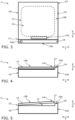
- Figure 3 shows a plan view of the steam cooking drawer 1 according to the invention with the lid 14 closed.
- Figure 4 shows the representation of the Figure 3 from the side.
- Figure 5 shows the representation of the Figure 4 with partially opened lid 14.
- the kitchen furniture 2 which can also be referred to as a kitchen unit 2, has a furniture front 20 or several furniture panels 20, with which the kitchen furniture 2 is closed off towards a user in the longitudinal direction X.
- the furniture front 20 is formed by several doors, flaps and the like (not designated), possibly also drawers (not shown), which are arranged pivotably, foldably or pullably on a frame 21, rack 21 or body 21 of the kitchen furniture 2.
- a steam cooking drawer 1 according to the invention is arranged approximately centrally along the vertical direction Z between two furniture fronts 20.
- the steam cooking drawer 1 has an outer housing 10, which can also be referred to as an outer housing 10 and essentially closes or encloses the steam cooking drawer 1 to the outside.
- the outer housing 10 closes along the longitudinal direction X to the front, ie towards the user, with a front panel 10a, which, when the steam cooking drawer 1 is pushed in, is flush with the furniture fronts 20 of the kitchen furniture 2, see Figure 1 .
- a pair of telescopic rails (not shown) are arranged laterally in the transverse direction Y on the outer housing 10 so that the steam cooking drawer 1 can be pulled out and pushed in in the longitudinal direction X relative to the frame 20 of the kitchen furniture 2.
- An inner housing 11 is arranged within the outer housing 10, which can also be referred to as the inner housing 11.
- the inner housing 11 ends in the longitudinal direction X to the rear and to the front up to the front panel 10a, in the vertical direction Z downwards and in the transverse direction Y on both sides with the outer housing 10, so that a gap (not shown) is formed between the outer housing 10 and the inner housing 11, which can also be referred to as the housing space. This gap represents the interior of the steam cooking drawer 1.
- the inner housing 11 also essentially encloses an interior space 12 in which a cooking process or a steam cooking process can be carried out.
- a steam generator (not shown) is arranged in the housing space or in the space between the steam cooking drawer 1, which evaporates water and transfers the water vapor into the interior space 12.
- the interior space 12 can also be referred to as the cooking space 12.
- the interior 12 can be moved out of the outer housing 10.
- the interior 12 is arranged on a pull-out or the inner housing 11 is at least partially designed as a pull-out.
- a pull-out is the movable part, preferably mounted on rails.
- the front panel 10a can also be arranged on the pull-out.
- the interior 12 is accessible to the user from above through an access opening 13 in the vertical direction Z.
- the access opening 13 can be closed and opened by means of a closure element 14 in the form of a lid 14.
- the lid 14 Facing the interior 12, the lid 14 has a bottom 14a or an inner side 14a and opposite it a top 14b or an outer side 14b.
- the lid 14 is connected to the outer housing 10 of the steam cooking drawer 1 by means of at least one pivoting element 15 in the form of a hinge 15 or lid hinge 15 so that it can pivot upwards in the vertical direction Z, so that the lid 14 can be pivoted away from the user or up towards the furniture panel 20 located above it in order to be able to access the cooking chamber 12 when the steam cooking drawer 1 is pulled out, see Figure 2 . If the lid 14 is swung down to the horizontal X, Y, the cooking chamber 12 is closed and the steam cooking drawer 1 can be pushed into the kitchen unit 2, see Figure 1 .
- the closed lid 14 can be opened by means of an operating element 16a of an operating panel 16, which runs in the horizontal X, Y and is arranged along the longitudinal axis X between the upper edge (not designated) of the front panel 10a and the front edge (not designated) of the closed lid 14 or the access opening 13, cf. Figures 3 and 4 .
- the control panel 16 is narrow along the longitudinal axis X and extends along the transverse axis Y completely over the entire width of the steam cooking drawer 1. Along the longitudinal axis X, the control panel 16 is spaced from the closed lid 14 by a gap 17.
- the closed lid 14 is held mechanically by a detachable hook (not shown) against the spring force of a spiral spring (not shown) of the hinge 15.
- the user can reach and operate the control panel 16 or its control element 16a directly with his finger. This allows the hook to be mechanically pulled back and the spring-loaded closed lid 14 to be released.
- the lid 14 can now be opened at least sufficiently far around the Fold the pivot axis of the hinge 15 upwards, facing the user or the control panel 16, see Figure 5 to be grasped by the user and folded up completely and thus opened.
- the control panel 16 with the control element 16a is arranged facing the user. For this reason, a certain distance is also provided along the longitudinal axis X between the edge of the closed lid 14 facing the user or the control panel 16 and the control element 16a, so that the hot steam rising along the vertical axis Z keeps the area above the control element 16a away, where the user's hand or a finger is located at the moment of actuation and thus opening of the closed lid 14.
- the top side 14b of the lid 14 has a control surface 14c which is made of a material with comparatively poor heat conduction and is therefore always heated or warmed up comparatively little.
- the user can fold the opened lid 14 down again until the weight of the opened lid 14 is held by the spiral spring of the hinge 15. The user can then press from above on the control surface 14c of the opened lid 14 and thereby completely close the lid 14 and hook it back in place.
Landscapes
- Engineering & Computer Science (AREA)
- Chemical & Material Sciences (AREA)
- Combustion & Propulsion (AREA)
- Mechanical Engineering (AREA)
- General Engineering & Computer Science (AREA)
- Cookers (AREA)
Applications Claiming Priority (1)
| Application Number | Priority Date | Filing Date | Title |
|---|---|---|---|
| BE20235089A BE1031328B1 (de) | 2023-02-07 | 2023-02-07 | Dampfgarschublade |
Publications (1)
| Publication Number | Publication Date |
|---|---|
| EP4414616A1 true EP4414616A1 (fr) | 2024-08-14 |
Family
ID=86688706
Family Applications (1)
| Application Number | Title | Priority Date | Filing Date |
|---|---|---|---|
| EP24152326.5A Pending EP4414616A1 (fr) | 2023-02-07 | 2024-01-17 | Tiroir pour la cuisson à la vapeur |
Country Status (2)
| Country | Link |
|---|---|
| EP (1) | EP4414616A1 (fr) |
| BE (1) | BE1031328B1 (fr) |
Cited By (2)
| Publication number | Priority date | Publication date | Assignee | Title |
|---|---|---|---|---|
| DE102024203575A1 (de) * | 2024-04-17 | 2025-10-23 | BSH Hausgeräte GmbH | Gargutbehandlungsschublade mit durch Push/Push-Einheit betätigbarem Deckel |
| DE102024209734A1 (de) * | 2024-10-04 | 2026-04-09 | BSH Hausgeräte GmbH | Öffnen eines Deckels einer Wärmebehandlungsschublade |
Citations (1)
| Publication number | Priority date | Publication date | Assignee | Title |
|---|---|---|---|---|
| DE102020105146A1 (de) | 2020-02-27 | 2021-09-02 | Miele & Cie. Kg | Gargerät und Verfahren zum Betreiben |
-
2023
- 2023-02-07 BE BE20235089A patent/BE1031328B1/de active IP Right Grant
-
2024
- 2024-01-17 EP EP24152326.5A patent/EP4414616A1/fr active Pending
Patent Citations (1)
| Publication number | Priority date | Publication date | Assignee | Title |
|---|---|---|---|---|
| DE102020105146A1 (de) | 2020-02-27 | 2021-09-02 | Miele & Cie. Kg | Gargerät und Verfahren zum Betreiben |
Cited By (2)
| Publication number | Priority date | Publication date | Assignee | Title |
|---|---|---|---|---|
| DE102024203575A1 (de) * | 2024-04-17 | 2025-10-23 | BSH Hausgeräte GmbH | Gargutbehandlungsschublade mit durch Push/Push-Einheit betätigbarem Deckel |
| DE102024209734A1 (de) * | 2024-10-04 | 2026-04-09 | BSH Hausgeräte GmbH | Öffnen eines Deckels einer Wärmebehandlungsschublade |
Also Published As
| Publication number | Publication date |
|---|---|
| BE1031328A1 (de) | 2024-09-11 |
| BE1031328B1 (de) | 2024-09-16 |
Similar Documents
| Publication | Publication Date | Title |
|---|---|---|
| BE1031328B1 (de) | Dampfgarschublade | |
| EP3470739A1 (fr) | Appareil de cuisson et procédé de mise en uvre d'un procédé de traitement | |
| DE102021105049A1 (de) | Einbaugargerät | |
| CH647587A5 (en) | Device for baking and roasting | |
| EP0034295A2 (fr) | Installation de cuisine encastrée | |
| EP3647664B1 (fr) | Procédé de fonctionnement automatique d'un appareil de cuisson à la vapeur et appareil de cuisson à la vapeur correspondant | |
| BE1029164B1 (de) | Einbauküchengerät | |
| DE3814253A1 (de) | Haushalt-mikrowellenofen fuer den einbau oder die aufstellung unterhalb des niveaus der arbeitsflaeche | |
| EP4053456B1 (fr) | Système d'appareil de cuisson | |
| BE1031059B1 (de) | Küchengerät | |
| BE1029165B1 (de) | Gargerätesystem | |
| EP4053459A1 (fr) | Appareil de cuisson encastrable | |
| DE102021105050A1 (de) | Einbaugargerät | |
| EP1488720B1 (fr) | Creuset avec couvercle et mécanisme de fermeture | |
| BE1031289B1 (de) | Küchengerät | |
| BE1029171B1 (de) | Einbaugargerät | |
| EP4374752B1 (fr) | Appareil de cuisine | |
| BE1031414B1 (de) | Gargerätschublade, vorzugsweise Dampfgarschublade | |
| BE1029169B1 (de) | Gargerät, vorzugsweise Einbaugargerät | |
| EP4054291B1 (fr) | Appareil de cuisson | |
| BE1031057B1 (de) | Küchengerät | |
| DE102020200077A1 (de) | Anordnung mit Arbeitsplatte und versenkbaren Kochfeld | |
| BE1031060B1 (de) | Küchengerät | |
| EP3708043A1 (fr) | Rôtissoire | |
| DE102022130787A1 (de) | Küchengerät |
Legal Events
| Date | Code | Title | Description |
|---|---|---|---|
| PUAI | Public reference made under article 153(3) epc to a published international application that has entered the european phase |
Free format text: ORIGINAL CODE: 0009012 |
|
| STAA | Information on the status of an ep patent application or granted ep patent |
Free format text: STATUS: THE APPLICATION HAS BEEN PUBLISHED |
|
| AK | Designated contracting states |
Kind code of ref document: A1 Designated state(s): AL AT BE BG CH CY CZ DE DK EE ES FI FR GB GR HR HU IE IS IT LI LT LU LV MC ME MK MT NL NO PL PT RO RS SE SI SK SM TR |
|
| STAA | Information on the status of an ep patent application or granted ep patent |
Free format text: STATUS: REQUEST FOR EXAMINATION WAS MADE |
|
| 17P | Request for examination filed |
Effective date: 20250214 |