EP4414657A1 - Palpeur de mesure - Google Patents
Palpeur de mesure Download PDFInfo
- Publication number
- EP4414657A1 EP4414657A1 EP23155632.5A EP23155632A EP4414657A1 EP 4414657 A1 EP4414657 A1 EP 4414657A1 EP 23155632 A EP23155632 A EP 23155632A EP 4414657 A1 EP4414657 A1 EP 4414657A1
- Authority
- EP
- European Patent Office
- Prior art keywords
- housing part
- groove
- contour
- measuring probe
- positive
- Prior art date
- Legal status (The legal status is an assumption and is not a legal conclusion. Google has not performed a legal analysis and makes no representation as to the accuracy of the status listed.)
- Pending
Links
- 239000000523 sample Substances 0.000 title claims abstract description 53
- 239000000463 material Substances 0.000 claims description 8
- 238000000034 method Methods 0.000 claims description 8
- 238000007789 sealing Methods 0.000 claims description 7
- 238000004519 manufacturing process Methods 0.000 claims description 5
- 238000003825 pressing Methods 0.000 claims description 2
- 239000000853 adhesive Substances 0.000 description 3
- 230000001070 adhesive effect Effects 0.000 description 3
- 239000000565 sealant Substances 0.000 description 3
- 238000011161 development Methods 0.000 description 2
- 230000018109 developmental process Effects 0.000 description 2
- 238000006073 displacement reaction Methods 0.000 description 2
- 239000007789 gas Substances 0.000 description 2
- 238000010438 heat treatment Methods 0.000 description 2
- 239000007788 liquid Substances 0.000 description 2
- 229910000831 Steel Inorganic materials 0.000 description 1
- 238000004026 adhesive bonding Methods 0.000 description 1
- 230000032683 aging Effects 0.000 description 1
- 239000000956 alloy Substances 0.000 description 1
- 229910045601 alloy Inorganic materials 0.000 description 1
- 229910052782 aluminium Inorganic materials 0.000 description 1
- XAGFODPZIPBFFR-UHFFFAOYSA-N aluminium Chemical compound [Al] XAGFODPZIPBFFR-UHFFFAOYSA-N 0.000 description 1
- 230000000903 blocking effect Effects 0.000 description 1
- 238000005520 cutting process Methods 0.000 description 1
- 230000001419 dependent effect Effects 0.000 description 1
- 238000013461 design Methods 0.000 description 1
- 238000005553 drilling Methods 0.000 description 1
- 238000005516 engineering process Methods 0.000 description 1
- 238000003780 insertion Methods 0.000 description 1
- 230000037431 insertion Effects 0.000 description 1
- 238000009434 installation Methods 0.000 description 1
- 229910052751 metal Inorganic materials 0.000 description 1
- 239000002184 metal Substances 0.000 description 1
- 238000003801 milling Methods 0.000 description 1
- 238000012986 modification Methods 0.000 description 1
- 230000004048 modification Effects 0.000 description 1
- 238000012545 processing Methods 0.000 description 1
- 230000001105 regulatory effect Effects 0.000 description 1
- 238000010008 shearing Methods 0.000 description 1
- 239000007787 solid Substances 0.000 description 1
- 239000010959 steel Substances 0.000 description 1
Images




Classifications
-
- G—PHYSICS
- G01—MEASURING; TESTING
- G01B—MEASURING LENGTH, THICKNESS OR SIMILAR LINEAR DIMENSIONS; MEASURING ANGLES; MEASURING AREAS; MEASURING IRREGULARITIES OF SURFACES OR CONTOURS
- G01B5/00—Measuring arrangements characterised by the use of mechanical techniques
- G01B5/004—Measuring arrangements characterised by the use of mechanical techniques for measuring coordinates of points
- G01B5/008—Measuring arrangements characterised by the use of mechanical techniques for measuring coordinates of points using coordinate measuring machines
- G01B5/012—Contact-making feeler heads therefor
-
- G—PHYSICS
- G01—MEASURING; TESTING
- G01B—MEASURING LENGTH, THICKNESS OR SIMILAR LINEAR DIMENSIONS; MEASURING ANGLES; MEASURING AREAS; MEASURING IRREGULARITIES OF SURFACES OR CONTOURS
- G01B21/00—Measuring arrangements or details thereof, where the measuring technique is not covered by the other groups of this subclass, unspecified or not relevant
- G01B21/02—Measuring arrangements or details thereof, where the measuring technique is not covered by the other groups of this subclass, unspecified or not relevant for measuring length, width, or thickness
-
- G—PHYSICS
- G01—MEASURING; TESTING
- G01B—MEASURING LENGTH, THICKNESS OR SIMILAR LINEAR DIMENSIONS; MEASURING ANGLES; MEASURING AREAS; MEASURING IRREGULARITIES OF SURFACES OR CONTOURS
- G01B7/00—Measuring arrangements characterised by the use of electric or magnetic techniques
- G01B7/001—Constructional details of gauge heads
-
- G—PHYSICS
- G01—MEASURING; TESTING
- G01D—MEASURING NOT SPECIALLY ADAPTED FOR A SPECIFIC VARIABLE; ARRANGEMENTS FOR MEASURING TWO OR MORE VARIABLES NOT COVERED IN A SINGLE OTHER SUBCLASS; TARIFF METERING APPARATUS; MEASURING OR TESTING NOT OTHERWISE PROVIDED FOR
- G01D11/00—Component parts of measuring arrangements not specially adapted for a specific variable
-
- G—PHYSICS
- G01—MEASURING; TESTING
- G01D—MEASURING NOT SPECIALLY ADAPTED FOR A SPECIFIC VARIABLE; ARRANGEMENTS FOR MEASURING TWO OR MORE VARIABLES NOT COVERED IN A SINGLE OTHER SUBCLASS; TARIFF METERING APPARATUS; MEASURING OR TESTING NOT OTHERWISE PROVIDED FOR
- G01D11/00—Component parts of measuring arrangements not specially adapted for a specific variable
- G01D11/24—Housings ; Casings for instruments
-
- G—PHYSICS
- G01—MEASURING; TESTING
- G01D—MEASURING NOT SPECIALLY ADAPTED FOR A SPECIFIC VARIABLE; ARRANGEMENTS FOR MEASURING TWO OR MORE VARIABLES NOT COVERED IN A SINGLE OTHER SUBCLASS; TARIFF METERING APPARATUS; MEASURING OR TESTING NOT OTHERWISE PROVIDED FOR
- G01D11/00—Component parts of measuring arrangements not specially adapted for a specific variable
- G01D11/30—Supports specially adapted for an instrument; Supports specially adapted for a set of instruments
-
- G—PHYSICS
- G01—MEASURING; TESTING
- G01D—MEASURING NOT SPECIALLY ADAPTED FOR A SPECIFIC VARIABLE; ARRANGEMENTS FOR MEASURING TWO OR MORE VARIABLES NOT COVERED IN A SINGLE OTHER SUBCLASS; TARIFF METERING APPARATUS; MEASURING OR TESTING NOT OTHERWISE PROVIDED FOR
- G01D21/00—Measuring or testing not otherwise provided for
Definitions
- the present invention relates to a measuring probe according to the preamble of claim 1.
- screw connections to connect two housing parts of a measuring probe is known in the state of the art.
- the disadvantage here is that several processing steps are necessary to produce screw connections, such as drilling the core hole and countersink hole, deburring and, if necessary, cutting the internal thread several times.
- Another disadvantage is that when using screw connections, an increased need for installation space for the screw shaft and screw head must be planned, which is not always possible, especially with compact component groups.
- screw connections always carry the risk of unwanted media (such as liquids or gases) entering the interior of a component group.
- DE 31 20 492 A1 discloses a measuring device for mechanical workpieces with a displacement measuring device.
- the measuring device comprises a first and second part with rectangular-trapezoidal grooves for a sealing bellows. This sealing bellows seals the displacement measuring device against external influences using a press fit.
- One of the disadvantages of this solution is the increased manufacturing effort associated with such a press fit and compliance with specified tolerances.
- the object of the present invention is to provide a measuring probe which is cost-effective to manufacture and comprises the smallest possible number of components.
- the measuring probe comprises a first housing part for enclosing a shaft of the measuring probe extending in a longitudinal direction (x-direction) and a second housing part.
- the first housing part and the second housing part are connected to one another at least in a form-fitting manner in an overlapping region.
- the first housing part comprises at least one first groove arranged in the overlapping region.
- the second housing part comprises at least one first contour corresponding to the first groove.
- the first groove and the first contour form a first groove-contour pair.
- the measuring probe has at least one first form-fitting and force-fitting connection between the first housing part and the second housing part.
- the first positive and non-positive connection is formed by the first groove-contour pair.
- the first positive and non-positive connection is created by forming the second housing part.
- the forming is carried out by a local plastic material deformation of at least the second housing part in the region of the first groove.
- the shaft of the measuring probe serves as a holder for a probe element.
- the shaft is designed, for example, as a guide for a measuring bolt.
- the probe element comprises, for example, the measuring bolt and a variable measuring insert connected to the measuring bolt.
- the first housing part is essentially solid.
- the second housing part is essentially hollow with a wall thickness of 0.25 mm to 6 mm, for example.
- the second housing part can be plugged onto the first housing part along the longitudinal direction (x-direction), so that several (i.e. at least five) degrees of freedom are bound.
- the first groove is introduced into the first housing part, for example by milling or turning.
- the first contour is, for example, a press contour.
- the first housing part, the second housing part and the shaft can be made of metal or an alloy, in particular aluminum or steel, or plastic. All components can be made of an identical material, but various material combinations are also conceivable.
- the first housing part can also be called a guide sleeve.
- the second housing part can also be called a housing cap.
- a positive connection is a connection in which at least two connection partners (ie first and second housing part) engage with each other or into each other, so that a positive connection is achieved by the geometric contact of the active surfaces.
- one connection partner blocks the movement of the other, whereby the blocking effect with respect to at least one direction.
- a force-locking connection at least one movement of two connection partners (ie first and second housing part) is prevented or regulated by a system of friction-related forces (force-locking).
- a form-locking and force-locking connection is understood to mean a connection in which both a form-locking and a force-locking connection are present.
- the first contour extends in a vertical direction (z-direction) into the first groove.
- the first groove serves as a negative of the first contour and at least partially determines its course and shape.
- the first groove has a depth (in the vertical direction) corresponding to the first contour.
- the first groove-contour pair extends over less than one millimeter or alternatively up to several millimeters in the height direction (z-direction) in the direction of the first groove and thus in the direction of a (central) longitudinal axis of the measuring probe.
- This design advantageously enables a non-detachable connection between the first housing part and the second housing part.
- the first groove-contour pair extends in a transverse direction (y-direction).
- the measuring probe according to the invention is also advantageously designed such that the first housing part comprises a second groove arranged in the overlap region, wherein the second housing part comprises a second contour corresponding to the second groove.
- the second groove and the second contour form a second groove-contour pair.
- the measuring probe comprises at least one second positive and non-positive connection formed by the second groove-contour pair between the first housing part and the second housing part.
- the second positive and non-positive connection can also be produced by forming the second housing part, for example by a local plastic material deformation of at least the second housing part in the region of the second groove.
- a further advantageous embodiment of the invention provides that the first groove-contour pair and the second groove-contour pair are arranged on sides or sections of the measuring probe that are opposite one another in a height direction (z direction).
- This arrangement of the groove-contour pairs has the advantage that tensile, compressive and shearing forces that act on the measuring probe from the outside can be better compensated.
- more than one groove-contour pair can also be provided per side or section.
- the measuring probe according to the invention advantageously comprises an annular groove arranged in the overlapping area in the first housing part for receiving a sealing means, for example an O-ring, wherein the annular groove extends in a circumferential direction (radial direction in relation to the longitudinal axis of the measuring probe) partially or completely around the first housing part.
- the sealing means is arranged between the first housing part and the second housing part and seals the interior of the measuring probe against media (such as liquids or gases).
- the annular groove in combination with the sealant is advantageously arranged in the longitudinal direction (x-direction) in front of or behind the first groove-contour pair.
- the annular groove in combination with the sealant can be arranged in such a way that it is in front of the front or behind the last groove-contour pair.
- the annular groove can also be between two groove-contour pairs.
- several annular grooves can be provided, each with a sealant, which can be positioned between the several groove-contour pairs arranged one behind the other in the longitudinal direction (x-direction).
- the first contour and, alternatively or additionally, the first groove can advantageously each have a semicircular, rectangular, triangular or trapezoidal cross-section.
- the invention is advantageously designed such that the first housing part and the shaft are materially connected to one another (e.g. by gluing), so that a connection that cannot be easily separated is formed between the shaft and the first housing part.
- the first groove is designed as a closed or open groove.
- An open groove is a groove that does not have a groove outlet.
- An open groove can, for example, extend over the entire circumferential direction of the first housing part, so that it opens back into itself, as is the case with an annular groove in the circumferential direction.
- a closed groove i.e. non-open groove
- a closed groove therefore has a groove outlet at at least one end, which can be straight and in particular at a outlet angle or curved, in particular with a outlet radius.
- a first housing part with at least one first groove and a second housing part are provided. Furthermore, a positive connection of the first housing part and the second housing part is carried out by plugging the second housing part in a longitudinal direction (x-direction) onto the first housing part such that an overlap region is formed between the first housing part and the second housing part, and that the first groove is arranged in the overlap region. In addition, a positive and non-positive connection of the first housing part and the second housing part is carried out by forming the second housing part such that at least one first contour corresponding to the first groove is formed, and that the first groove and the first contour form a first groove-contour pair.
- the positive and non-positive connection is made in such a way that the first contour extends in a height direction (z-direction) into the first groove.
- the positive and non-positive connection advantageously comprises a targeted local plastic material deformation, for example with previously carried out heat treatment ((semi-)hot forming) at least in the overlap area or without heat treatment (cold forming).
- the positive and non-positive connection advantageously includes pressing or clinching the second housing part with the first housing part. This avoids the need for additional connecting elements such as screws or rivets. This is again relatively cost-effective.
- the positive and non-positive connection can include a temporary introduction of at least one stamping element to create the first contour.
- a stamping element is first sunk into the second housing part at the level of the first groove and a directed stamping force is transmitted.
- the second housing part undergoes a targeted local plastic material deformation, with the second housing part being stretched in this area, which creates the positive and non-positive connection.
- the present invention enables a measuring probe with a positive and non-positive connection between two housing parts and with a reduced number of components.
- the positive and non-positive connection of the two housing parts can be achieved by forming during the manufacture of the measuring probe, whereby a compact measuring probe with a reduced number of components can be realized.
- the figures show coordinate systems that indicate the longitudinal direction (x-direction), the transverse direction (y-direction) and the height direction (z-direction).
- the coordinate axes (x, y, z) of the coordinate systems are orthogonal to each other in pairs.
- Fig.1 shows a perspective view of a measuring probe T with a second housing part 2, which is positively and non-positively connected to a first housing part 1 by means of a first contour 2.1.
- the first housing part 1 is in turn materially connected to a shaft 3, whereby the shaft 3 additionally has a probe element 5.
- Fig.2 shows the measuring probe T in plan view, wherein the first contour 2.1 extends into the measuring probe T in an overlapping area of the first housing part 1 and the second housing part 2 as well as in the height direction z.
- the first contour 2.1 runs along a transverse direction y.
- Fig.3 shows a sectional view of the measuring probe T along the section line AA from Fig.2 .
- the first housing part 1 comprises a first groove 1.1, which extends along the height direction z into the measuring probe T.
- the second housing part 2 comprises the first contour 2.1, which is shaped and extends into the first groove 1.1 in a force-locking manner, so that a first groove-contour pair 10 is formed.
- a second groove 1.2 and a second contour 2.2 are formed, both of which extend into the measuring probe T along the height direction z and also form a form-locking and force-locking connection.
- the second groove 1.2 and the second contour 2.2 form a second groove-contour pair 20.
- the first housing part 1 comprises an annular groove 4.1 which is designed as a closed groove and runs in the circumferential direction.
- the annular groove 4.1 serves as a receptacle for a sealing means 4, for example an O-ring.
- Fig.4 shows the process step used to form the first contour 2.1 and the second contour 2.2.
- a stamping element S, S' is temporarily introduced into the area of the first groove 1.1 or the second groove 1.2 from the outside into the second housing part 2 in such a way that the first contour 2.1 or the second contour 2.2 is formed and a positive and non-positive connection is created between the first housing part 1 and the second housing part 2 at the corresponding point. This results in a local plastic material deformation of the second housing part 2.
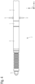
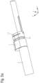
- the Figures 5a-5c show the first housing part 1 with the first groove 1.1 ( Fig. 5a ) and exemplary modifications thereof (hereinafter first groove 1.1' according to Fig. 5b ; first groove 1.11 according to Fig. 5c ).
- the first groove is, for example, with a rectangular cross-section (first groove 1.1 according to Fig. 5a ), a triangular cross-section (first groove 1.1' according to Fig. 5b ) or as a round hole (first groove 1.11 according to Fig. 5c ) is formed.
- Further round holes 1.12-1.14 can be provided.
- the first groove 1.11 and the holes 1.12-1.14 form a group in the form of a rectangular configuration (cf. Fig. 5c ).
- This group in conjunction with a corresponding contour of the second housing part 2 (not shown) can form additional groove-contour pairs on one side of the measuring probe T.
- the second groove 1.2 or a further group can be designed identically to the first groove 1.1, 1.1', 1.11 or to the aforementioned group 1.11-1.14 (not shown).
- the second groove 1.2 or the further group can be designed on the opposite side of the measuring probe T in the height direction z (in relation to the first groove 1.11, 1.1', 1.11 and the aforementioned group 1.11-1.14)
Landscapes
- Physics & Mathematics (AREA)
- General Physics & Mathematics (AREA)
- A Measuring Device Byusing Mechanical Method (AREA)
- Length Measuring Devices With Unspecified Measuring Means (AREA)
- Lining Or Joining Of Plastics Or The Like (AREA)
Priority Applications (4)
| Application Number | Priority Date | Filing Date | Title |
|---|---|---|---|
| EP23155632.5A EP4414657A1 (fr) | 2023-02-08 | 2023-02-08 | Palpeur de mesure |
| DE102023211293.0A DE102023211293A1 (de) | 2023-02-08 | 2023-11-14 | Messtaster und Verfahren zur Herstellung eines Messtasters |
| JP2024017067A JP2024112789A (ja) | 2023-02-08 | 2024-02-07 | 測定プローブおよび測定プローブを製造するための方法 |
| CN202410175252.1A CN118463881A (zh) | 2023-02-08 | 2024-02-07 | 测量探针和用于制造测量探针的方法 |
Applications Claiming Priority (1)
| Application Number | Priority Date | Filing Date | Title |
|---|---|---|---|
| EP23155632.5A EP4414657A1 (fr) | 2023-02-08 | 2023-02-08 | Palpeur de mesure |
Publications (1)
| Publication Number | Publication Date |
|---|---|
| EP4414657A1 true EP4414657A1 (fr) | 2024-08-14 |
Family
ID=85383029
Family Applications (1)
| Application Number | Title | Priority Date | Filing Date |
|---|---|---|---|
| EP23155632.5A Pending EP4414657A1 (fr) | 2023-02-08 | 2023-02-08 | Palpeur de mesure |
Country Status (4)
| Country | Link |
|---|---|
| EP (1) | EP4414657A1 (fr) |
| JP (1) | JP2024112789A (fr) |
| CN (1) | CN118463881A (fr) |
| DE (1) | DE102023211293A1 (fr) |
Citations (2)
| Publication number | Priority date | Publication date | Assignee | Title |
|---|---|---|---|---|
| DE3120492A1 (de) | 1980-06-02 | 1982-05-06 | Finike Italiana Marposs S.p.A., 40010 Bentivoglio, Bologna | Messvorrichtung fuer mechanische werkstuecke |
| DE3330018A1 (de) * | 1982-09-09 | 1984-03-15 | Finike Italiana Marposs S.p.A., 40010 Bentivoglio, Bologna | Patronenfoermiger messkopf |
-
2023
- 2023-02-08 EP EP23155632.5A patent/EP4414657A1/fr active Pending
- 2023-11-14 DE DE102023211293.0A patent/DE102023211293A1/de active Pending
-
2024
- 2024-02-07 JP JP2024017067A patent/JP2024112789A/ja active Pending
- 2024-02-07 CN CN202410175252.1A patent/CN118463881A/zh active Pending
Patent Citations (2)
| Publication number | Priority date | Publication date | Assignee | Title |
|---|---|---|---|---|
| DE3120492A1 (de) | 1980-06-02 | 1982-05-06 | Finike Italiana Marposs S.p.A., 40010 Bentivoglio, Bologna | Messvorrichtung fuer mechanische werkstuecke |
| DE3330018A1 (de) * | 1982-09-09 | 1984-03-15 | Finike Italiana Marposs S.p.A., 40010 Bentivoglio, Bologna | Patronenfoermiger messkopf |
Also Published As
| Publication number | Publication date |
|---|---|
| DE102023211293A1 (de) | 2024-08-08 |
| CN118463881A (zh) | 2024-08-09 |
| JP2024112789A (ja) | 2024-08-21 |
Similar Documents
| Publication | Publication Date | Title |
|---|---|---|
| DE102010042803B4 (de) | Bauteilverbindung | |
| DE102014105908B4 (de) | Werkzeug zur spanenden Bearbeitung eines Werkstücks und Verfahren zur Herstellung eines Werkzeugs | |
| DE202009014886U1 (de) | Kugelzapfen | |
| EP3690260B1 (fr) | Rivet auto-poinçonneur semi-tubulaire, raccordement riveté d'au moins deux composants à l'aide du rivet auto-poinçonneur semi-tubulaire ainsi que procédé de raccordement des composants au rivet auto-poinçonneur semi-tubulaire | |
| DE10348427A1 (de) | Verfahren und Vorrichtung zur Direktverschraubung | |
| DE19800097A1 (de) | Span- oder Schneidwerkzeug und Verfahren zu dessen Herstellung | |
| DE19704505A1 (de) | Verfahren zum Herstellen eines Verbinderbolzens | |
| EP3329500A1 (fr) | Dispositif antidéflagrant pour traversée de boulon et son procédé de fabrication | |
| DE4444908A1 (de) | Befestigungselement | |
| EP3568257B1 (fr) | Ensemble de pièces comprenant au moins deux pièces et procédé de production d'un ensemble de pièces assemblées par complémentarité de forme et/ou à force | |
| EP3837065B1 (fr) | Vis à résistance élevée en deux parties | |
| DE102007046788B3 (de) | Verfahren zum Herstellen eines Schließringbolzens und Schließringbolzen | |
| EP1276996B1 (fr) | Unite de montage constituee d'un composant et d'au moins une vis taraudeuse | |
| DE102023211293A1 (de) | Messtaster und Verfahren zur Herstellung eines Messtasters | |
| DE102022100748B3 (de) | Selbstsichernde, fluidische Klemmvorrichtung | |
| DE102020004055A1 (de) | Schweißgewindebolzen und Verfahren zum Befestigen eines Bauteils mit einem solchen Schweißgewindebolzen | |
| DE102013224314B4 (de) | Verfahren zur Herstellung zumindest einer Durchgangsöffnung in einem Fahrzeugbauteil | |
| DE102018124493A1 (de) | Gelenkgehäuse und Verfahren zur Herstellung eines Gelenkgehäuses | |
| DE19957076A1 (de) | Verfahren und Vorrichtung zum Lochen von Blechformteilen aus einem Aluminiumwerkstoff | |
| DE102018211566A1 (de) | Werkzeug und Verfahren zum Verpressen eines Hilfsfügeelements mit einem separat von dem Hilfsfügeelement ausgebildeten Werkstück, insbesondere zum Herstellen eines Kraftfahrzeugs | |
| DE102006018847B4 (de) | Verfahren und Vorrichtung zum Stanzen eines Loches mit kleinem Durchmesser-Längen-Verhältnis | |
| DE202007005755U1 (de) | Vorrichtung zum Stanzen eines Lochs in Blechen mit einer Fase | |
| DE102017115296A1 (de) | Verfahren zur Herstellung eines Durchzugniets | |
| DE10162392A1 (de) | Verfahren zum Verbinden von Bauteilen | |
| DE202010005349U1 (de) | Doppelstanzbuchse sowie System aus einem Rohr und einer Doppelstanzbuchse |
Legal Events
| Date | Code | Title | Description |
|---|---|---|---|
| PUAI | Public reference made under article 153(3) epc to a published international application that has entered the european phase |
Free format text: ORIGINAL CODE: 0009012 |
|
| STAA | Information on the status of an ep patent application or granted ep patent |
Free format text: STATUS: THE APPLICATION HAS BEEN PUBLISHED |
|
| AK | Designated contracting states |
Kind code of ref document: A1 Designated state(s): AL AT BE BG CH CY CZ DE DK EE ES FI FR GB GR HR HU IE IS IT LI LT LU LV MC ME MK MT NL NO PL PT RO RS SE SI SK SM TR |
|
| STAA | Information on the status of an ep patent application or granted ep patent |
Free format text: STATUS: REQUEST FOR EXAMINATION WAS MADE |
|
| 17P | Request for examination filed |
Effective date: 20250214 |