EP4414780A2 - Boîtier de flash pour des objectifs photographiques, ensemble comprenant un boîtier de flash pour des objectifs photographiques et au moins un outil de mise en forme de flash, et outil de mise en forme de flash - Google Patents
Boîtier de flash pour des objectifs photographiques, ensemble comprenant un boîtier de flash pour des objectifs photographiques et au moins un outil de mise en forme de flash, et outil de mise en forme de flash Download PDFInfo
- Publication number
- EP4414780A2 EP4414780A2 EP24185251.6A EP24185251A EP4414780A2 EP 4414780 A2 EP4414780 A2 EP 4414780A2 EP 24185251 A EP24185251 A EP 24185251A EP 4414780 A2 EP4414780 A2 EP 4414780A2
- Authority
- EP
- European Patent Office
- Prior art keywords
- flash
- flash light
- light shaping
- shaping tool
- housing
- Prior art date
- Legal status (The legal status is an assumption and is not a legal conclusion. Google has not performed a legal analysis and makes no representation as to the accuracy of the status listed.)
- Pending
Links
Images


Classifications
-
- G—PHYSICS
- G03—PHOTOGRAPHY; CINEMATOGRAPHY; ANALOGOUS TECHNIQUES USING WAVES OTHER THAN OPTICAL WAVES; ELECTROGRAPHY; HOLOGRAPHY
- G03B—APPARATUS OR ARRANGEMENTS FOR TAKING PHOTOGRAPHS OR FOR PROJECTING OR VIEWING THEM; APPARATUS OR ARRANGEMENTS EMPLOYING ANALOGOUS TECHNIQUES USING WAVES OTHER THAN OPTICAL WAVES; ACCESSORIES THEREFOR
- G03B15/00—Special procedures for taking photographs; Apparatus therefor
- G03B15/02—Illuminating scene
- G03B15/03—Combinations of cameras with lighting apparatus; Flash units
-
- G—PHYSICS
- G03—PHOTOGRAPHY; CINEMATOGRAPHY; ANALOGOUS TECHNIQUES USING WAVES OTHER THAN OPTICAL WAVES; ELECTROGRAPHY; HOLOGRAPHY
- G03B—APPARATUS OR ARRANGEMENTS FOR TAKING PHOTOGRAPHS OR FOR PROJECTING OR VIEWING THEM; APPARATUS OR ARRANGEMENTS EMPLOYING ANALOGOUS TECHNIQUES USING WAVES OTHER THAN OPTICAL WAVES; ACCESSORIES THEREFOR
- G03B15/00—Special procedures for taking photographs; Apparatus therefor
- G03B15/02—Illuminating scene
- G03B15/03—Combinations of cameras with lighting apparatus; Flash units
- G03B15/05—Combinations of cameras with electronic flash apparatus; Electronic flash units
-
- F—MECHANICAL ENGINEERING; LIGHTING; HEATING; WEAPONS; BLASTING
- F21—LIGHTING
- F21V—FUNCTIONAL FEATURES OR DETAILS OF LIGHTING DEVICES OR SYSTEMS THEREOF; STRUCTURAL COMBINATIONS OF LIGHTING DEVICES WITH OTHER ARTICLES, NOT OTHERWISE PROVIDED FOR
- F21V21/00—Supporting, suspending, or attaching arrangements for lighting devices; Hand grips
- F21V21/08—Devices for easy attachment to any desired place, e.g. clip, clamp, magnet
- F21V21/096—Magnetic devices
-
- G—PHYSICS
- G03—PHOTOGRAPHY; CINEMATOGRAPHY; ANALOGOUS TECHNIQUES USING WAVES OTHER THAN OPTICAL WAVES; ELECTROGRAPHY; HOLOGRAPHY
- G03B—APPARATUS OR ARRANGEMENTS FOR TAKING PHOTOGRAPHS OR FOR PROJECTING OR VIEWING THEM; APPARATUS OR ARRANGEMENTS EMPLOYING ANALOGOUS TECHNIQUES USING WAVES OTHER THAN OPTICAL WAVES; ACCESSORIES THEREFOR
- G03B15/00—Special procedures for taking photographs; Apparatus therefor
- G03B15/02—Illuminating scene
- G03B15/06—Special arrangements of screening, diffusing, or reflecting devices, e.g. in studio
-
- G—PHYSICS
- G03—PHOTOGRAPHY; CINEMATOGRAPHY; ANALOGOUS TECHNIQUES USING WAVES OTHER THAN OPTICAL WAVES; ELECTROGRAPHY; HOLOGRAPHY
- G03B—APPARATUS OR ARRANGEMENTS FOR TAKING PHOTOGRAPHS OR FOR PROJECTING OR VIEWING THEM; APPARATUS OR ARRANGEMENTS EMPLOYING ANALOGOUS TECHNIQUES USING WAVES OTHER THAN OPTICAL WAVES; ACCESSORIES THEREFOR
- G03B2215/00—Special procedures for taking photographs; Apparatus therefor
- G03B2215/05—Combinations of cameras with electronic flash units
- G03B2215/0582—Reflectors
- G03B2215/0585—Movable reflectors, e.g. change of illumination angle or direction
-
- G—PHYSICS
- G03—PHOTOGRAPHY; CINEMATOGRAPHY; ANALOGOUS TECHNIQUES USING WAVES OTHER THAN OPTICAL WAVES; ELECTROGRAPHY; HOLOGRAPHY
- G03B—APPARATUS OR ARRANGEMENTS FOR TAKING PHOTOGRAPHS OR FOR PROJECTING OR VIEWING THEM; APPARATUS OR ARRANGEMENTS EMPLOYING ANALOGOUS TECHNIQUES USING WAVES OTHER THAN OPTICAL WAVES; ACCESSORIES THEREFOR
- G03B2215/00—Special procedures for taking photographs; Apparatus therefor
- G03B2215/05—Combinations of cameras with electronic flash units
- G03B2215/0589—Diffusors, filters or refraction means
- G03B2215/0592—Diffusors, filters or refraction means installed in front of light emitter
Definitions
- the present disclosure relates to a flash housing for photographic purposes.
- the present disclosure further relates to a set comprising a flash housing for photographic purposes and at least one flash light shaping tool.
- the present disclosure further relates to a flash light shaping tool for attachment to a flash housing for photographic purposes.
- a flash device In order to be able to take photographs of a certain quality a flash device is often used to provide light or to improve the light in the photograph.
- flash housings known in the art arranged to generate a flash light and to let at least part of the generated flash light out of the flash housing so as to obtain the flash light.
- One object of the present disclosure is to obtain an improve use of flash light shaping tools.
- the flash housing comprises a flash forming element arranged to generate a flash light, a lens element arranged to let at least part of the generated flash out of the flash housing so as to obtain a flash light, and a fastening element for attachment of a flash light shaping tool on top of the lens element.
- the fastening element is arranged at least partly along a border of the lens element for magnetic engagement with a corresponding fastening element at the flash light shaping tool.
- the magnetic mounting of flash light shaping tools to the flash housing provides a mounting of flash light shaping tools which is user friendly and easy to use. Flash light shaping tools can easily be mounted and demounted to adapt the flash light as desired.
- the flash housing fastening element comprises at least one permanent magnet.
- the flash housing fastening element may be at least partly formed by a ferromagnetic material arranged to magnetically engage with the fastening element of the flash light shaping tool, comprising at least one permanent magnet.
- the flash housing fastening element may enclose the entire border of the lens element.
- the lens element has in one option a substantially circular cross-section.
- the cross section is defined in a direction substantially perpendicular to the beam lobe axis of the flash light.
- the flash housing fastening element may when the lens element has a circular cross section comprise a ring shaped element.
- the ring shaped element may be provided with the permanent magnet(s).
- the ring shaped element may be at least partly made of the ferromagnetic material for magnetic engagement with permanent magnet(s).
- the flash housing comprises in different embodiments a zoom element rotatably arranged coaxially with and outside the flash housing fastening element and operatively connected to the flash forming element so as to control movement of the flash forming element by manual rotation of the zoom element.
- the present disclosure further relates to a set comprising a flash housing for photographic purposes and at least one flash light shaping tool, wherein the flash housing comprises a flash forming element arranged to generate a flash light and a lens element arranged to let at least part of the generated flash light out of the flash housing so as to obtain a flash light, and wherein the flash housing and the at least one flash light shaping tool comprises a respective fastening element for magnetic attachment of the flash light shaping tool on top of the lens element.
- the flash housing fastening element may be arranged at least partly along the border of the lens element for magnetic engagement with the corresponding fastening element at the flash light shaping tool.
- the flash housing fastening element may comprise at least one permanent magnet and the flash light shaping tool fastening element may be at least partly formed by a ferromagnetic material arranged to magnetically engage with the fastening element of the flash housing.
- the fastening element of the flash light shaping tool comprises in one option at least one permanent magnet and the flash housing fastening element is in one option at least partly formed by a ferromagnetic material arranged to engage with the fastening element of the flash light shaping tool.
- the flash housing fastening element and/or the flash light shaping tool fastening element may enclose the entire border of the lens element or at least one part thereof.
- the flash light shaping tools are in one option stackable.
- the flash light shaping tools may be attachable to each other by magnetic engagement.
- a plurality of flash light shaping tools may then be stacked on top of each other on the lens element to provide desired light shaping effects.
- each of the at least one flash light shaping tool may then comprise a respective additional fastening element for magnetic attachment of another flash light shaping tool on top of one flash light shaping tool.
- Different embodiments of the present disclosure relates to a flash light shaping tool for attachment to a flash housing for photographic purposes.
- the flash housing comprises a flash forming element arranged to generate a flash light and a lens element arranged to let at least part of the generated flash light out of the flash housing so as to obtain a flash light and a fastening element for attachment of a flash light shaping tool on top of the lens element.
- the flash light shaping tool comprises a first fastening element for magnetic attachment or engagement on top of the flash housing lens element.
- the flash light shaping tool is in one option stackable.
- the flash light shaping tool may be attachable to another flash light shaping tool by magnetic engagement.
- the flash light shaping tool may further comprise a second fastening element for magnetic engagement with another flash light shaping tool on top of the flash light shaping tool.
- the first and second fastening elements are arranged in the beam path at different sides of the flash light shaping tool.
- the flash light shaping tool comprises a holder for a flash light shaping element.
- the holder or flash light shaping element may be rotatable in relation to the lens element of the flash housing.
- the flash light shaping tool comprises a flash light shaping element attached or attachable to and extending from the holder.
- the flash light shaping element comprises a screen.
- the screen is arranged in the beam path of at least a part of the flash light.
- the flash light shaping element may also comprise a support for the screen. The holder may then hold the support, which in turn may hold the screen.
- the screen may be at least partly reflective and arranged to re-direct at least a part of the flash light.
- the screen may when mounted cover a part of the beam lobe of the flash light so that this part of the flash light is reflected by the screen and the rest of the flash light is not incident on and reflected by the screen.
- the screen may be arranged in a desired rotational position in relation to the flash housing.
- the orientation of the flash housing may be orientated such that the part of the flash light which is incident on the screen is reflected towards the object to be photographed while the other part not incident on the flash light hits a bouncing surface such as the roof.
- the screen may be arranged to diffuse at least a part of the flash light.
- the screen may be made of a textile material.
- the screen may be hood shaped.
- the hood When the flash light emitted from the lens element of the flash housing is incident on the interior of the hood, the hood reflects the incident light.
- the hood shape and the surface characteristics of the hood may cooperate to direct and diffuse flash light to obtain a softened light.
- the hood shaped screen is collapsible and spring loaded.
- the spring is substantially un-tensioned or semi-tensioned when the hood in its unfolded state and tensioned when the hood is in its collapsed state.
- the flash light shaping element supported by the holder may comprise a lens.
- the flash light shaping element may for example comprise a dome shaped diffuser element, a wide lens, a colour filter etc.
- the first and/or second fastening element(s) may be accommodated in the holder.
- the holder may comprise a first and a second holder part arranged to support an exchangeable flash light shaping element by magnetic engagement between the first and second holder parts.
- the first and second fastening elements may be arranged to provide the magnetic engagement between the first and second holder parts.
- the flash light shaping tool may further comprise third and fourth fastening elements arranged to provide the magnetic engagement between the first and second holder parts.
- the present disclosure relates in different embodiments to fastening of one flash light shaping tool, or a plurality of stacked flash shaping tools, on top of a lens element of a flash housing.
- the fastening is achieved by magnetic engagement or actuation.
- the flash housing has a fastening element arranged at least partly along a border of the lens element for magnetic engagement with a corresponding fastening element at the flash light shaping tool.
- the flash light shaping tool is arranged to affect at least a part of the beam lobe emitted through the lens element of the flash housing to improve or adapt the properties of the flash light to achieve desired flash light effects in a photograph.
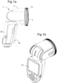
- FIGS 1a and 1b illustrate a flash device 1 according to one example.
- the flash device 1 is arranged to be used for photographic purposes.
- the flash device 1 is arranged to be releasably attachable to a camera.
- the flash device 1 comprises in the illustrated example a flash holder 20 and a flash housing 2 hinged onto the flash holder 20.
- the flash device further comprises a releasable battery 30, attached to the flash holder 20.
- the flash housing is equipped with a lens element 3 arranged to affect the generated flash light in a desired way.
- the flash device 1 further has a display element 23.
- a flash housing 2 for photographic purposes is illustrated.
- the flash housing is arranged to obtain a flash light.
- the flash housing comprises a lens element 3.
- the flash housing 2 comprises a flash forming element (not shown) arranged to generate a flash light.
- the lens element 3 is arranged to let at least part of the generated flash out of the flash housing so as to obtain a flash light.
- the lens element 3 has in the illustrated example a substantially circular cross-section.
- the cross section is characteristically arranged perpendicular to a main direction of the flash light let out of the lens element.
- the lens element may have any other shape such as an oval or rectangular shape.
- the flash housing 2 comprises further at least one fastening element 25 for attachment of a flash light shaping tool (not shown) on top of the lens element 3.
- the at least one fastening element 25 is arranged at least partly along a border of the lens element 3 for magnetic engagement with a corresponding fastening element at the flash light shaping tool.
- the fastening element 25 of the flash house may enclose the entire border of the lens element or a part thereof.
- the flash housing fastening element 25 may comprise at least one permanent magnet 26.
- the flash housing fastening element may comprise a plurality of permanent magnets arranged along the border of the lens element 3.
- the flash housing fastening element 25 comprises a supporting structure arranged along the border of the lens element 3, wherein the supporting structure holds one or a plurality of the permanent magnets 26.
- the supporting structure is ring shaped.
- the ring shaped supporting structure may be arranged at the edge of the lens element.
- the ring shaped supporting structure may be arranged on a part of the lens element external surface adjacent to the edge.
- the ring shaped supporting structure may be arranged at the flash housing coaxially with and outside the lens element 3.
- the ring shaped supporting structure may be made of a metal material.
- the fastening element 25 may be so arranged that at least a part of the at least one permanent magnet 26 extends from the plane of the external lens element surface. Thereby the permanent magnet is easily accessible for attachment to the flash light shaping tool.
- the fastening element 25 may be arranged in a recess in the housing, providing a guide for the mounting of the flash light shaping tool. Thereby the mounting is user friendly as a correct positioning of the flash light shaping tool on top of the lens element is facilitated.
- the fastening element 25 of the flash housing may be at least partly formed by a ferromagnetic material arranged to magnetically engage with the fastening element of the flash light shaping tool, wherein the fastening element of the flash light shaping tool comprises at least one permanent magnet.
- the fastening element may be arranged along at least a part of the border of the lens element 3.
- the fastening element may be ring shaped.
- the ring shaped fastening element may be arranged at the edge of the lens element.
- the ring fastening element may be arranged on a part of the lens element external surface adjacent to the edge.
- the ring shaped fastening element may be arranged at the flash housing coaxially with and outside the lens element.
- the fastening element may be so arranged that it at least partly extends from the plane of the external lens element surface. Thereby the fastening element is easily accessible for attachment to the permanent magnet(s) of the fastening element of the flash light shaping tool.
- the fastening element may instead be arranged in a recess in the housing, providing a guide for the mounting of the flash light shaping tool. Thereby the mounting is user friendly as a correct positioning of the flash light shaping tool on top of the lens element is facilitated.
- the flash housing may further comprise a zoom element 21 rotatably arranged coaxially with and outside the flash housing fastening element 25.
- the zoom element is operatively connected to the flash forming element so as to control movement of the flash forming element within the flash housing by manual rotation of the zoom element. This will be discussed more in detail later.
- Figure 3 discloses a flash housing 2 for photographic purposes having at least some of the features as discussed in relation to figure 2 .
- the flash housing comprises a lens element 3.
- the flash housing 2 comprises a further at least one fastening element 25 for attachment of a flash light shaping tool on top of the lens element 3.
- the at least one fastening element 25 is arranged at least partly along a border of the lens element 3 for magnetic engagement with a corresponding fastening element at the flash light shaping tool.
- the fastening element 25 of the flash housing may enclose the entire border of the lens element or a part thereof.
- the flash housing fastening element 25 may comprise at least one permanent magnet 26.
- the flash housing fastening element comprises in the illustrated example a plurality of permanent magnets arranged along the border of the lens element 3.
- a set 40 comprising a flash device 1 for photographic purposes and at least one flash light shaping tool 27.
- the flash device has a flash housing 2.
- the flash housing 2 comprises a flash forming element arranged to generate a flash light (not shown).
- the flash housing comprises further a lens element 3 arranged to let at least part of the generated flash light out of the flash housing so as to obtain a flash light.
- the flash housing 2 comprises further at least one fastening element (not shown) for attachment of the flash light shaping tool 27 on top of the lens element 3.
- the at least one fastening element of the flash housing is arranged at least partly along a border of the lens element 3 for magnetic engagement with a corresponding fastening element 28 at the flash light shaping tool.
- the fastening element of the flash housing 2 may enclose the entire border of the lens element or a part thereof.
- the flash housing fastening element may comprise at least one permanent magnet.
- the flash housing fastening element may comprise a plurality of permanent magnets arranged along the border of the lens element 3.
- the flash housing fastening element may be at least partly formed by a ferromagnetic material arranged to be attracted to the at least one permanent magnet of the flash housing fastening element.
- the flash light shaping tool 27 comprises a holder 31 for a flash light shaping element 29.
- the holder supports the fastening element 28 for magnetic attachment of the flash light shaping tool on top of the lens element.
- the flash housing fastening element is arranged at least partly along the border of the lens element for magnetic engagement with the corresponding fastening element 28 at the flash light shaping tool 27.
- the flash light shaping tool fastening element 28 is at least partly formed by a ferromagnetic material arranged to engage with the fastening element of the flash housing.
- the flash housing fastening element may at least partly be formed by a ferromagnetic material arranged to engage with the fastening element 28 of the flash light shaping tool.
- the flash housing fastening element and/or the flash light shaping tool fastening element 28 may be arranged to enclose the entire border of the lens element.
- the lens element 3 may have has a substantially circular cross-section in a direction perpendicular to the main direction of the flash light let out of the lens 3.
- the lens element may for example instead have an oval or rectangular shape.
- the flash housing fastening element and the fastening element 28 of the flash light shaping tool 27 are designed to fit with the design of the lens element 3.
- the flash light shaping tool 27 comprises a flash light shaping element.
- the flash light shaping element is a dome shaped diffuser element 29.
- the dome shaped diffuser element 29 is arranged to diffuse and spread the flash light emitted via the lens element 3 omni directionally. This is for example used when bouncing the light in the ceiling to get a softer and less directional light In opeation, the user can then direct the flash housing against the surface, such as the ceiling, to bounce off from.
- Flash shaping tools having different properties may be used provided with the magnetic mount disclosed herein.
- the flash shaping tool may comprise a bounce card and/or a filter such as a colour filter and/or a wide lens. Examples of some flash light shaping tools will be discussed more in detail below.
- the flash shaping tool may be stacked together with other light shaping tools.
- the flash light shaping tools are attachable to each other by magnetic engagement. This will be discussed more in detail below.
- the light shaping tool 27' may be stackable with other flash light shaping tools.
- the stackable flash light shaping tool 27' comprises a holder 31 arranged to support a flash light shaping element 29'.
- the holder 31 supports a fastening element 28 for magnetic attachment of the flash light shaping tool on top of the lens element or for magnetic attachment to another flash light shaping tool.
- the holder supports on its opposite side an additional fastening element 32 for magnetic attachment to another light shaping tool on top of the flash light shaping tool 27'.
- the flash light let out of the lens element of the flash housing may be shaped by a wide lens and/or a colour filter and/or a bounce card by magnetically stacking together different flash light shaping tools, as desired.
- the additional fastening element 32 comprises then characteristically a ferromagnetic material.
- the additional fastening element 32 comprises then characteristically at least one permanent magnet.
- the flash light shaping element is a dome shaped diffuser element 29'.
- the dome shaped diffuser element 29' is arranged to diffuse and spread the flash light emitted via the lens element 3 omni directionally. This is for example used when bouncing the light in the ceiling to get a softer and less directional light. In opeation, the user can then direct the flash housing against the surface, such as the ceiling, to bounce off from.
- FIG 6 another example of a light shaping tool 27" is illustrated.
- the light shaping tool may be stackable with other flash light shaping tools.
- the flash light shaping tool 27" comprises a holder 31 arranged to support a flash light shaping element 29".
- the holder 31 supports a fastening element 28 for magnetic attachment of the flash light shaping tool on top of the lens element or for magnetic attachment to another flash light shaping tool.
- the holder may further support on its opposite side an additional fastening element 32 for magnetic attachment to another light shaping tool on top of the flash light shaping tool 27".
- the flash light let out of the lens element of the flash housing may be shaped by a wide lens and/or a colour filter and/or a bounce card by magnetically stacking together different flash light shaping tools, as desired.
- the additional fastening element 32 comprises then characteristically a ferromagnetic material.
- the additional fastening element 32 comprises then characteristically at least one permanent magnet.
- the flash light shaping element 29" is a wide lens.
- the wide lens may be used when a wider light spread is needed.
- FIGS 7a-7c yet another example of a flash light shaping tool 27′′′ is illustrated.
- the flash light shaping tool 27′′′ comprises a holder 31 for a flash light shaping element29′′′.
- the holder 31 is provided with a fastening element, as has been discussed for example in relation to figures 5 and 6 .
- the flash light shaping tool may be stackable. Accordingly, the holder 31 may be provided with fastening elements at both sides for magnetic engagement with other flash light tools or flash housing.
- the flash light shaping element29′′′ comprises a screen 34 attached or attachable to and extending from a support 33 for the screen 34.
- the support 33 is mounted to the holder 31.
- the screen 34 is mounted such that it is placed in the beam path of at least a part of the flash light.
- the screen may be rotated in relation to the flash housing to a desired position.
- the screen 34 is at least partly reflective and arranged to re-direct at least a part of the flash light.
- the reflective screen 34 may be referred to as a bounce card.
- the application for the bounce card is similar to that of the dome shaped diffuser but provides a more directional light quality.
- the bounce card is in the illustrated example attached to the support 33 by squeezing the bounce card slightly and then pushing it firmly into the support 33 until the bounce card 34 locks in place.
- the bounce card 34 covers characteristically when mounted a part of beam lobe of the flash light so that a part of the flash light is reflected by the bounce card and the rest of the flash light is not incident on the bounce card.
- the bounce card may be rotated on the flash housing to direct the flash light as desired.
- the flash housing and/or bounce card may be orientated such that the part of the flash light which is incident on the bounce card is reflected towards the object to be photographed while the other part not incident on the flash light hits a bouncing surface such as the roof.
- FIGS 8a-8c another example of a flash light shaping tool 27 ⁇ is illustrated.
- the light shaping tool may be stackable with other flash light shaping tools.
- This flash light shaping tool 27 ⁇ is characteristically arranged to diffuse and direct the flash light to obtain a softened light.
- This flash light shaping tool 27 ⁇ may for example be used for portrait photographing.
- the flash light shaping tool 27 ⁇ comprises a holder 31 for a flash light shaping element 29 ⁇ .
- the holder 31 is attachable to the flash light housing by means of a magnetic mount.
- the holder 31 has therefore fastening element(s) for example as discussed in relation to figures 5 and 6 .
- the flash light shaping element 29 ⁇ comprises a screen 36 attached or attachable to and extending from the holder 31.
- the screen 36 is mounted to the holder 31 such that it is placed in the beam path of at least a part of the flash light.
- the screen 36 is at least partly reflective and arranged to re-direct and/or diffuse at least a part of the flash light.
- the screen 36 is hood shaped. Thus, it has side walls and a roof and an opening for letting out the flash light. At least a part of the flash light emitted from the lens element of the flash housing is incident on the interior of the hood.
- the hood functions as a large bounce card. In one example, substantially the whole beam lobe hits the interior of the hood.
- the hood shaped screen 36 may for example be made of a textile material.
- the hood shape and the surface characteristics of the textile material cooperate to direct and diffuse the flash light to obtain the softened light.
- the hood shaped screen 36 may be collapsible and spring loaded.
- the hood may be formed by two or more textile pieces and at least two spring loaded arcs 35.
- the ends of the arcs 35 are supported in the holder 31.
- the textile material forms an envelope surface enveloping the arcs 35 mounted to the holder 31.
- the textile material further extends to the holder and is attached to the holder 31 to obtain the hood shape.
- One opening is defined in the hood to let out the flash light.
- the spring (s) are semi-tensioned or substantially un-tensioned when the hood in its unfolded state and tensioned when the hood is in its collapsed state.
- the hood is characteristically collapsed by pushing the hood backwards.
- the flash light shaping tool 27 ⁇ can then be stored in a package in the tensioned, collapsed state, where the package is sized to fit the flash light shaping tool 27 ⁇ in the tensioned, collapsed state. Once the flash light shaping tool 27 ⁇ has been removed from the package, the flash light shaping tool 27 ⁇ is automatically resumed to the semi-tensioned or substantially un-tensioned, unfolded state.
- the light shaping tool may be stackable.
- the stackable flash light shaping tool 27′′′ ⁇ has a holder comprises two holder parts 31a, 31b arranged to support one or a plurality of exchangeable flash light shaping elements 29′′′ ⁇ .
- the holder parts 31a, 31b are arranged to support the flash light shaping element(s) by magnetic action between the first and second holder parts.
- the exchangeable flash light shaping elements may include different colour filters.
- the holder parts 31a, 31b supports a fastening element (not shown) for magnetic attachment of the flash light shaping tool on top of the lens element or for magnetic attachment to another flash light shaping tool.
- the holder supports on its opposite side an additional fastening element (not shown) for magnetic attachment to another light shaping tool on top of the flash light shaping tool 27′′′ ⁇ .
- the fastening elements as discussed for example in relation to figures 5 and 6 for enabling stacking of the light shaping tools magnetically may be designed to provide the magnetic action between the holder parts 31a, 31b.
- additional fastening elements are arranged at the holder parts 31a, 31b to provide the magnetic action between the holder parts.
- FIG 10 a perspective view of illustrating an example of the interior of a flash housing 2 for photographic purposes is illustrated.
- the flash light shaping tool, or a plurality of stacked flash shaping tools, as discussed herein may be used together with flash housing as disclosed in this example.
- the flash housing 2 comprises a zoom element 21 rotatably arranged at least partly along the circumference of the lens element (not shown).
- the zoom element 21 is operatively connected to the flash forming element 10 so as to control movement of the flash forming element by manual rotation of the zoom element.
- the zoom element 21 is arranged to control movement of the flash forming element 10 to obtain a flash light having a beam lobe with a desired beam angle.
- the flash forming element 10 is axially movable within the flash housing 2 to control the beam angle of the flash light beam lobe.
- the rotational movement of the zoom element 21 is mechanically translated to the axial movement of the flash forming element.
- the flash housing 2 comprises a transfer element 24 arrange to transfer the rotational movement or position of the zoom element 21 to an electrical signal.
- the axial movement or position of the flash forming element 10 is controlled based on the electrical signal.
- the transfer element 24 comprises for example a potentiometer, a Hall element, optical sensors or the like, arranged to transfer the rotational movement or position of the zoom element to the electrical signal.
- Different solutions for translating an axial movement or position to an electrical signal are well known in the art and will not be discussed in further detail herein.
- the electrical signal controls a positioner 14, 15, 16 for control of the movement or the position of the flash forming element.
- the flash forming element 10 is axially movable within the flash housing 2 to control the beam angle of the flash light beam lobe.
- the positioner is arranged to perform control of the positioner between two end positions, wherein when the flash forming element is in a first end position distant from the lens element, the flash light is incident on substantially the entire lens element and when the flash forming element is in a second end position closest to the lens element, the flash light is mainly incident on a center part of the lens element.
- the flash light beam lobe may have an essentially circular cross section.
- the positioner 14, 15, 16 may comprise a motor 14.
- the motor may be an electrical motor.
- the electrical motor may be a step motor 14.
- the step motor is arranged to provide an angular rotation corresponding to the electrical signal fed to the positioner 14, 15, 16.
- the positioner further comprises a screw element 15.
- the screw element 15 is rotated axially back and forward by means of the step motor.
- the positioner may further comprise a guided nut 16 in engagement with the screw element 15.
- the flash forming element 10 is supported by the guiding nut 16.
- the guided nut is guided within the flash housing such that it is movable in an axial direction along the screw element and fixed in an angular direction. Thus, the guided nut can not 16 rotate.
- the flash forming element will be axially controlled back and forward within the flash housing based on the electrical signal provided by the rotation of the zoom element.
- the flash forming element 10 is supported in a holder, which in turn is fastened to the guided nut 16.
- the flash forming element or holder holding the flash forming element, is further supported by at least one guiding pin 17 suspended in the flash housing.
- This at least one pin is mounted within the housing coaxially with the screw element 15.
- the function of the at least one simulation light element 11 guiding pin 17 is to further secure that the flash forming element is stably arranged within the flash housing and prevented to perform any rotational movements.
- Said flash housing comprises:
- the flash housing fastening element may comprise at least one permanent magnet.
- the flash housing fastening element may be at least partly formed by a ferromagnetic material arranged to engage with the fastening element of the flash light shaping tool comprising at least one permanent magnet.
- the flash housing fastening element may enclose the entire border of the lens element.
- the lens element may have a substantially circular cross-section.
- the flash housing may further comprise a zoom element rotatably arranged coaxially with and outside the flash housing fastening element and operatively connected to the flash forming element so as to control movement of the flash forming element by manual rotation of the zoom element.
- a set comprising a flash housing for photographic purposes and at least one flash light shaping tool,
- the flash housing fastening element comprises at least one permanent magnet and wherein the flash light shaping tool fastening element is at least partly formed by a ferromagnetic material arranged to engage with the fastening element of the flash housing.
- the fastening element of the flash light shaping tool may comprise at least one permanent magnet, wherein the flash housing fastening element is at least partly formed by a ferromagnetic material arranged to engage with the fastening element of the flash light shaping tool.
- the flash housing fastening element and/or the flash light shaping tool fastening element may enclose the entire border of the lens element.
- the lens element may have a substantially circular cross-section.
- the flash housing may further comprise a zoom element rotatably arranged coaxially with and outside the flash housing fastening element and operatively connected to the flash forming element so as to control movement of the flash forming element by manual rotation of the zoom element.
- the set may comprise a plurality of flash light shaping tools that are stackable.
- the plurality of flash light shaping tools may be connected to each other by magnetic engagement.
- Each one of the at least one flash light shaping tool may comprise a respective additional fastening element for magnetic engagement with another light shaping tool on top of one flash light shaping tool.
- a flash light shaping tool for attachment to a flash housing for photographic purposes.
- Said flash housing comprises a flash forming element arranged to generate a flash light and a lens element arranged to let at least part of the generated flash light out of the flash housing so as to obtain a flash light and a fastening element for attachment of a flash light shaping tool.
- the fastening element is configured for attachment of a flash light shaping tool on top of the lens element.
- the flash light shaping tool comprises a first fastening element for magnetic engagement with the flash housing on top of the flash housing lens element.
- the flash light shaping tool may be stackable.
- the flash light shaping tool may be attachable to another flash light shaping tool by magnetic engagement.
- the flash light shaping tool may further comprise a second fastening element for magnetic engagement with another flash light shaping tool on top of the flash light shaping tool.
- the flash light shaping tool may comprise a holder for a flash light shaping element.
- the flash light shaping element may comprise a screen and being attached or attachable to and extending from the holder, wherein said screen being arranged in the beam path of at least a part of the flash light.
- the screen may be at least partly reflective and arranged to re-direct at least a part of the flash light.
- the screen may be arranged to diffuse at least a part of the flash light.
- the screen may be made of a textile material.
- the screen may be hood shaped.
- the hood shaped screen may be collapsible and spring loaded and the spring may be semi-tensioned or substantially un-tensioned when the hood shaped screen is in its unfolded state and tensioned when the hood shaped screen is in its collapsed state.
- the flash light shaping element supported by the holder may comprise a lens.
- Said first and/or second fastening element may be accommodated in said holder.
- the holder may comprise a first and a second holder part arranged to support an exchangeable flash light shaping element by magnetic engagement between the first and second holder parts.
- the first and second fastening elements may bearranged to provide the magnetic engagement.
- the flash light shaping tool may further comprise third and fourth fastening elements arranged to provide the magnetic engagement between the first and second holder parts.
Landscapes
- Physics & Mathematics (AREA)
- General Physics & Mathematics (AREA)
- Engineering & Computer Science (AREA)
- General Engineering & Computer Science (AREA)
- Stroboscope Apparatuses (AREA)
- Accessories Of Cameras (AREA)
Applications Claiming Priority (3)
| Application Number | Priority Date | Filing Date | Title |
|---|---|---|---|
| SE1751152 | 2017-09-18 | ||
| PCT/SE2018/050945 WO2019054937A1 (fr) | 2017-09-18 | 2018-09-17 | Boîtier de flash pour usage photographique, ensemble comprenant un boîtier de flash pour usage photographique et au moins un outil de formation de lumière flash, et outil de formation de lumière flash |
| EP18856800.0A EP3685229B1 (fr) | 2017-09-18 | 2018-09-17 | Boîtier de flash pour usage photographique, ensemble comprenant un boîtier de flash pour usage photographique et au moins un outil de formation de lumière flash, et outil de formation de lumière flash |
Related Parent Applications (1)
| Application Number | Title | Priority Date | Filing Date |
|---|---|---|---|
| EP18856800.0A Division EP3685229B1 (fr) | 2017-09-18 | 2018-09-17 | Boîtier de flash pour usage photographique, ensemble comprenant un boîtier de flash pour usage photographique et au moins un outil de formation de lumière flash, et outil de formation de lumière flash |
Publications (2)
| Publication Number | Publication Date |
|---|---|
| EP4414780A2 true EP4414780A2 (fr) | 2024-08-14 |
| EP4414780A3 EP4414780A3 (fr) | 2024-11-13 |
Family
ID=65722955
Family Applications (2)
| Application Number | Title | Priority Date | Filing Date |
|---|---|---|---|
| EP24185251.6A Pending EP4414780A3 (fr) | 2017-09-18 | 2018-09-17 | Boîtier de flash pour des objectifs photographiques, ensemble comprenant un boîtier de flash pour des objectifs photographiques et au moins un outil de mise en forme de flash, et outil de mise en forme de flash |
| EP18856800.0A Active EP3685229B1 (fr) | 2017-09-18 | 2018-09-17 | Boîtier de flash pour usage photographique, ensemble comprenant un boîtier de flash pour usage photographique et au moins un outil de formation de lumière flash, et outil de formation de lumière flash |
Family Applications After (1)
| Application Number | Title | Priority Date | Filing Date |
|---|---|---|---|
| EP18856800.0A Active EP3685229B1 (fr) | 2017-09-18 | 2018-09-17 | Boîtier de flash pour usage photographique, ensemble comprenant un boîtier de flash pour usage photographique et au moins un outil de formation de lumière flash, et outil de formation de lumière flash |
Country Status (5)
| Country | Link |
|---|---|
| US (2) | US11630375B2 (fr) |
| EP (2) | EP4414780A3 (fr) |
| CN (3) | CN109521629B (fr) |
| ES (1) | ES2991447T3 (fr) |
| WO (1) | WO2019054937A1 (fr) |
Families Citing this family (3)
| Publication number | Priority date | Publication date | Assignee | Title |
|---|---|---|---|---|
| WO2019054937A1 (fr) * | 2017-09-18 | 2019-03-21 | Profoto Aktiebolag | Boîtier de flash pour usage photographique, ensemble comprenant un boîtier de flash pour usage photographique et au moins un outil de formation de lumière flash, et outil de formation de lumière flash |
| WO2024040763A1 (fr) * | 2022-08-26 | 2024-02-29 | 深圳市神牛摄影器材有限公司 | Lampe pour photographie et enregistrement vidéo |
| USD1013022S1 (en) * | 2022-12-06 | 2024-01-30 | Shenzhen Neewer Technology Co. Ltd | Flash trigger |
Family Cites Families (49)
| Publication number | Priority date | Publication date | Assignee | Title |
|---|---|---|---|---|
| US3049611A (en) | 1960-08-22 | 1962-08-14 | Honeywell Regulator Co | Photographic flash unit |
| JPS5839456Y2 (ja) | 1976-10-29 | 1983-09-06 | ウエスト電気株式会社 | 写真用閃光装置 |
| US5019845A (en) * | 1989-06-23 | 1991-05-28 | Olympus Optical Co., Ltd. | Flash device for camera |
| US5208624A (en) | 1991-10-10 | 1993-05-04 | Sony Corporation Of America | Camera lens and filter adapter assembly |
| US5839006A (en) * | 1996-10-30 | 1998-11-17 | Beckerman; Arnold Edward | Apparatus and method for directing light from a swivel flash head |
| JP3823450B2 (ja) * | 1997-06-18 | 2006-09-20 | 株式会社ニコン | カメラの内蔵ストロボ |
| JP4053247B2 (ja) * | 2000-09-19 | 2008-02-27 | ペンタックス株式会社 | フラッシュ撮影システム及びカメラ |
| US6709121B1 (en) | 2002-09-24 | 2004-03-23 | Chimera Company | Lightbank with releasable support rod mounts |
| US7380966B2 (en) | 2004-11-24 | 2008-06-03 | Gary Fong, Inc. | Photographic light diffuser |
| US7519287B2 (en) | 2005-08-19 | 2009-04-14 | Avago Technologies Ecbu Ip (Singapore) Pte, Ltd. | Electronic flash, imaging device and method for producing a flash of light having a rectangular radiation pattern |
| US7360909B1 (en) * | 2005-12-01 | 2008-04-22 | Jerry Hughes | Photographic light reflector |
| JP2007206137A (ja) | 2006-01-31 | 2007-08-16 | Marumi Koki Kk | 携帯電話用カメラにおける交換レンズ並びにフィルターのマウント装置 |
| US7978971B1 (en) * | 2010-03-26 | 2011-07-12 | David Honl | Collapsible softbox for photography lighting |
| KR20080024030A (ko) | 2006-09-12 | 2008-03-17 | 엘지이노텍 주식회사 | 휴대 단말기의 플래쉬 장치 |
| JP2009020298A (ja) | 2007-07-11 | 2009-01-29 | Nikon Corp | 照明装置、照明装置に対する装着物、カメラ、照明システム、及び、カメラシステム |
| KR200448503Y1 (ko) | 2008-06-28 | 2010-04-21 | 고영국 | 카메라플래쉬의 만능 필터마운터 |
| US20100124041A1 (en) | 2008-11-17 | 2010-05-20 | Vitaly Druchinin | Systems and methods for controlling flash color temperature |
| JP5434580B2 (ja) | 2009-12-28 | 2014-03-05 | パナソニック株式会社 | ストロボ装置 |
| CN201628835U (zh) | 2010-01-26 | 2010-11-10 | 深圳市元科摄影器材有限公司 | 照相机机顶闪光灯光线调节配件转接装置 |
| CN201716503U (zh) | 2010-04-02 | 2011-01-19 | 深圳市永诺摄影器材有限公司 | 一种闪光灯 |
| US8886027B1 (en) * | 2010-06-15 | 2014-11-11 | Yishai Shapir | Photographic apparatus and method |
| CN102346354B (zh) | 2010-08-02 | 2014-02-19 | 王顺辰 | 多功能可折叠相机闪光灯控光附件 |
| TWI443382B (zh) * | 2010-08-31 | 2014-07-01 | Wintek Corp | 發光裝置及其透鏡 |
| CN102116998B (zh) | 2010-09-21 | 2012-07-04 | 陕西师范大学 | 高清晰度高温摄像装置 |
| CN102062332B (zh) | 2010-10-26 | 2012-06-27 | 江苏奥雷光电有限公司 | 视频监控照明led组件 |
| CN201903739U (zh) | 2010-12-13 | 2011-07-20 | 周思都 | 闪光灯用调节罩 |
| US20120154627A1 (en) * | 2010-12-20 | 2012-06-21 | William Rivard | Systems and methods for controlling color balance for a photographic illuminator |
| US20120268913A1 (en) * | 2011-04-22 | 2012-10-25 | Dana Ng | Flash unit diffuser with wings |
| GB2497129A (en) | 2011-12-02 | 2013-06-05 | Tony Ting Mo Chau | Camera flash gun diffuser |
| CN202403105U (zh) | 2011-12-24 | 2012-08-29 | 浙江海振电子科技有限公司 | 一种可变光谱的led灯 |
| US9049361B2 (en) | 2012-01-06 | 2015-06-02 | Canon Kabushiki Kaisha | Illumination device capable of having optical accessory attached forward of light emission section thereof, image pickup system, film holder, light emission control device, and light emission control method |
| JP2013142883A (ja) | 2012-01-13 | 2013-07-22 | Canon Inc | 閃光装置を含むカメラシステム |
| US9042719B2 (en) | 2012-11-20 | 2015-05-26 | Ye Xu | Magnetic lens filters and adapter assemblies for a camera |
| US8712234B1 (en) * | 2012-11-28 | 2014-04-29 | Ken M. Lau | Compact light shield for flash photography |
| JP6304930B2 (ja) * | 2013-02-21 | 2018-04-04 | キヤノン株式会社 | 光学アクセサリ用アダプタ |
| US20140375828A1 (en) | 2013-03-15 | 2014-12-25 | AmigoBooth, LLC | Apparatus, systems, and methods for capturing and displaying an image |
| US9357109B2 (en) | 2013-06-13 | 2016-05-31 | Carson Optical, Inc. | Magnetic optical adapter for electronic devices |
| US10054846B1 (en) | 2013-10-04 | 2018-08-21 | MagnetMod, LLC | Camera accessory mounting element |
| JP2015141381A (ja) * | 2014-01-30 | 2015-08-03 | 日清工業有限公司 | ストロボ装置 |
| CN203811960U (zh) | 2014-04-29 | 2014-09-03 | 吴惠芳 | 多功能外闪光线控制套件 |
| CN203909860U (zh) | 2014-06-10 | 2014-10-29 | 上海远欧国际贸易有限公司 | 一种带偏光镜及广角镜的行车记录仪 |
| TWM488654U (zh) | 2014-06-24 | 2014-10-21 | Nai-Qi Shi | 控光裝置 |
| CN204314583U (zh) | 2014-11-27 | 2015-05-06 | 吕元胜 | 闪光灯柔光罩 |
| EP3313272A4 (fr) | 2015-06-23 | 2019-02-20 | Metaoptima Technology Inc. | Appareil pour l'imagerie de la peau |
| CN206191526U (zh) | 2016-11-08 | 2017-05-24 | 广州市美铿摄影器材有限公司 | 一种摄影闪光灯磁吸方式控光组件 |
| US20180205864A1 (en) * | 2017-01-17 | 2018-07-19 | Bby Solutions, Inc. | Camera Mounted LED Telephoto Spotlight |
| US10942423B1 (en) * | 2017-06-16 | 2021-03-09 | Apple Inc. | Light source module with adjustable focus |
| WO2019054937A1 (fr) | 2017-09-18 | 2019-03-21 | Profoto Aktiebolag | Boîtier de flash pour usage photographique, ensemble comprenant un boîtier de flash pour usage photographique et au moins un outil de formation de lumière flash, et outil de formation de lumière flash |
| KR102101785B1 (ko) | 2018-05-18 | 2020-04-17 | 신선영 | 디지털 카메라용 조명기기 |
-
2018
- 2018-09-17 WO PCT/SE2018/050945 patent/WO2019054937A1/fr not_active Ceased
- 2018-09-17 US US16/629,019 patent/US11630375B2/en active Active
- 2018-09-17 EP EP24185251.6A patent/EP4414780A3/fr active Pending
- 2018-09-17 ES ES18856800T patent/ES2991447T3/es active Active
- 2018-09-17 EP EP18856800.0A patent/EP3685229B1/fr active Active
- 2018-09-18 CN CN201811086537.9A patent/CN109521629B/zh active Active
- 2018-09-18 CN CN202310767091.0A patent/CN116880113A/zh active Pending
- 2018-09-18 CN CN201821523510.7U patent/CN209248218U/zh not_active Expired - Fee Related
-
2023
- 2023-04-17 US US18/301,587 patent/US20230350272A1/en active Granted
Non-Patent Citations (1)
| Title |
|---|
| ANONYMOUS: "Flens - The first flashlight booster for smartphones by Basilico - Kickstarter", 16 July 2017 (2017-07-16), pages 1 - 20, XP093365624, Retrieved from the Internet <URL:https://web.archive.org/web/20170716175457/kickstarter.com/projects/basilico/flens-the-first-flashlight-booster-for-smartphones> * |
Also Published As
| Publication number | Publication date |
|---|---|
| CN116880113A (zh) | 2023-10-13 |
| EP3685229A4 (fr) | 2021-04-28 |
| ES2991447T3 (es) | 2024-12-03 |
| CN109521629B (zh) | 2023-07-18 |
| US20200233282A1 (en) | 2020-07-23 |
| US20230350272A1 (en) | 2023-11-02 |
| EP4414780A3 (fr) | 2024-11-13 |
| WO2019054937A1 (fr) | 2019-03-21 |
| CN209248218U (zh) | 2019-08-13 |
| EP3685229C0 (fr) | 2024-07-31 |
| EP3685229B1 (fr) | 2024-07-31 |
| US11630375B2 (en) | 2023-04-18 |
| EP3685229A1 (fr) | 2020-07-29 |
| CN109521629A (zh) | 2019-03-26 |
Similar Documents
| Publication | Publication Date | Title |
|---|---|---|
| US20230350272A1 (en) | Flash housing for photographic purposes, a set comprising a flash housing for photographic purposes and at least one flash light shaping tool, and a flash light shaping tool | |
| CN100592192C (zh) | 放大用附件 | |
| KR101963546B1 (ko) | 소형 접이식 카메라의 오토 포커스 및 광학 이미지 안정화 | |
| JP5411255B2 (ja) | 全天周パノラマ映像撮影補助装置 | |
| US20150212395A1 (en) | Imaging apparatus and imaging system | |
| JP2016039472A (ja) | 撮像装置 | |
| CN113542538A (zh) | 一种摄像头以及终端设备 | |
| JP2002236248A (ja) | レンズ鏡筒 | |
| US9201210B2 (en) | Lens driving device | |
| HK40102333A (zh) | 闪光灯壳体、闪光灯光成形工具以及套件 | |
| KR20230012813A (ko) | 스마트폰 천체사진 촬영용 망원경 | |
| US20250321470A1 (en) | Mounting bracket, filter unit, and photography auxiliary device | |
| US20120301128A1 (en) | Viewfinder | |
| US20250244554A1 (en) | Smartphone camera filters | |
| TWM535011U (zh) | 便攜式電子裝置 | |
| JPS6159976A (ja) | 電子カメラ | |
| JP2019138973A (ja) | 撮像装置 | |
| WO2016059437A1 (fr) | Perfectionnements apportés à l'acquisition d'image | |
| JP2021067828A (ja) | カメラ支持具 | |
| JP6492689B2 (ja) | カメラ撮影補助具 | |
| TW201017323A (en) | Lens seated device for driving single lens reflex camera zooming | |
| JP2022176134A (ja) | カメラモジュール | |
| KR20110000048U (ko) | 카메라의 빛망울 효과용 외부 필터 | |
| JP2011221299A (ja) | 撮影レンズにおける前面アクセサリの着脱機構 | |
| JP2007110472A (ja) | 監視カメラの取り付け装置および監視カメラ装置 |
Legal Events
| Date | Code | Title | Description |
|---|---|---|---|
| PUAI | Public reference made under article 153(3) epc to a published international application that has entered the european phase |
Free format text: ORIGINAL CODE: 0009012 |
|
| STAA | Information on the status of an ep patent application or granted ep patent |
Free format text: STATUS: THE APPLICATION HAS BEEN PUBLISHED |
|
| AC | Divisional application: reference to earlier application |
Ref document number: 3685229 Country of ref document: EP Kind code of ref document: P |
|
| AK | Designated contracting states |
Kind code of ref document: A2 Designated state(s): AL AT BE BG CH CY CZ DE DK EE ES FI FR GB GR HR HU IE IS IT LI LT LU LV MC MK MT NL NO PL PT RO RS SE SI SK SM TR |
|
| REG | Reference to a national code |
Ref country code: DE Ref legal event code: R079 Free format text: PREVIOUS MAIN CLASS: G03B0017120000 Ipc: G03B0015060000 |
|
| PUAL | Search report despatched |
Free format text: ORIGINAL CODE: 0009013 |
|
| AK | Designated contracting states |
Kind code of ref document: A3 Designated state(s): AL AT BE BG CH CY CZ DE DK EE ES FI FR GB GR HR HU IE IS IT LI LT LU LV MC MK MT NL NO PL PT RO RS SE SI SK SM TR |
|
| RIC1 | Information provided on ipc code assigned before grant |
Ipc: G03B 17/12 20210101ALI20241007BHEP Ipc: G03B 17/04 20210101ALI20241007BHEP Ipc: G03B 15/05 20210101ALI20241007BHEP Ipc: G03B 15/06 20210101AFI20241007BHEP |
|
| STAA | Information on the status of an ep patent application or granted ep patent |
Free format text: STATUS: REQUEST FOR EXAMINATION WAS MADE |
|
| 17P | Request for examination filed |
Effective date: 20250428 |
|
| STAA | Information on the status of an ep patent application or granted ep patent |
Free format text: STATUS: EXAMINATION IS IN PROGRESS |
|
| 17Q | First examination report despatched |
Effective date: 20260227 |