EP4414846A1 - Procédé et appareil de traitement d'informations de défaut - Google Patents
Procédé et appareil de traitement d'informations de défaut Download PDFInfo
- Publication number
- EP4414846A1 EP4414846A1 EP22885058.2A EP22885058A EP4414846A1 EP 4414846 A1 EP4414846 A1 EP 4414846A1 EP 22885058 A EP22885058 A EP 22885058A EP 4414846 A1 EP4414846 A1 EP 4414846A1
- Authority
- EP
- European Patent Office
- Prior art keywords
- interface
- chip
- fault information
- fault
- mac
- Prior art date
- Legal status (The legal status is an assumption and is not a legal conclusion. Google has not performed a legal analysis and makes no representation as to the accuracy of the status listed.)
- Pending
Links
Images

Classifications
-
- G—PHYSICS
- G06—COMPUTING OR CALCULATING; COUNTING
- G06F—ELECTRIC DIGITAL DATA PROCESSING
- G06F11/00—Error detection; Error correction; Monitoring
- G06F11/22—Detection or location of defective computer hardware by testing during standby operation or during idle time, e.g. start-up testing
- G06F11/26—Functional testing
- G06F11/273—Tester hardware, i.e. output processing circuits
- G06F11/2733—Test interface between tester and unit under test
-
- H—ELECTRICITY
- H04—ELECTRIC COMMUNICATION TECHNIQUE
- H04L—TRANSMISSION OF DIGITAL INFORMATION, e.g. TELEGRAPHIC COMMUNICATION
- H04L41/00—Arrangements for maintenance, administration or management of data switching networks, e.g. of packet switching networks
- H04L41/06—Management of faults, events, alarms or notifications
-
- H—ELECTRICITY
- H04—ELECTRIC COMMUNICATION TECHNIQUE
- H04L—TRANSMISSION OF DIGITAL INFORMATION, e.g. TELEGRAPHIC COMMUNICATION
- H04L43/00—Arrangements for monitoring or testing data switching networks
- H04L43/08—Monitoring or testing based on specific metrics, e.g. QoS, energy consumption or environmental parameters
- H04L43/0805—Monitoring or testing based on specific metrics, e.g. QoS, energy consumption or environmental parameters by checking availability
- H04L43/0817—Monitoring or testing based on specific metrics, e.g. QoS, energy consumption or environmental parameters by checking availability by checking functioning
-
- G—PHYSICS
- G06—COMPUTING OR CALCULATING; COUNTING
- G06F—ELECTRIC DIGITAL DATA PROCESSING
- G06F11/00—Error detection; Error correction; Monitoring
- G06F11/22—Detection or location of defective computer hardware by testing during standby operation or during idle time, e.g. start-up testing
-
- G—PHYSICS
- G06—COMPUTING OR CALCULATING; COUNTING
- G06F—ELECTRIC DIGITAL DATA PROCESSING
- G06F11/00—Error detection; Error correction; Monitoring
- G06F11/22—Detection or location of defective computer hardware by testing during standby operation or during idle time, e.g. start-up testing
- G06F11/2205—Detection or location of defective computer hardware by testing during standby operation or during idle time, e.g. start-up testing using arrangements specific to the hardware being tested
- G06F11/221—Detection or location of defective computer hardware by testing during standby operation or during idle time, e.g. start-up testing using arrangements specific to the hardware being tested to test buses, lines or interfaces, e.g. stuck-at or open line faults
-
- G—PHYSICS
- G06—COMPUTING OR CALCULATING; COUNTING
- G06F—ELECTRIC DIGITAL DATA PROCESSING
- G06F11/00—Error detection; Error correction; Monitoring
- G06F11/22—Detection or location of defective computer hardware by testing during standby operation or during idle time, e.g. start-up testing
- G06F11/26—Functional testing
- G06F11/273—Tester hardware, i.e. output processing circuits
-
- H—ELECTRICITY
- H04—ELECTRIC COMMUNICATION TECHNIQUE
- H04L—TRANSMISSION OF DIGITAL INFORMATION, e.g. TELEGRAPHIC COMMUNICATION
- H04L41/00—Arrangements for maintenance, administration or management of data switching networks, e.g. of packet switching networks
- H04L41/06—Management of faults, events, alarms or notifications
- H04L41/0677—Localisation of faults
-
- H—ELECTRICITY
- H04—ELECTRIC COMMUNICATION TECHNIQUE
- H04L—TRANSMISSION OF DIGITAL INFORMATION, e.g. TELEGRAPHIC COMMUNICATION
- H04L43/00—Arrangements for monitoring or testing data switching networks
- H04L43/06—Generation of reports
- H04L43/065—Generation of reports related to network devices
-
- H—ELECTRICITY
- H04—ELECTRIC COMMUNICATION TECHNIQUE
- H04L—TRANSMISSION OF DIGITAL INFORMATION, e.g. TELEGRAPHIC COMMUNICATION
- H04L43/00—Arrangements for monitoring or testing data switching networks
- H04L43/08—Monitoring or testing based on specific metrics, e.g. QoS, energy consumption or environmental parameters
- H04L43/0823—Errors, e.g. transmission errors
-
- H—ELECTRICITY
- H04—ELECTRIC COMMUNICATION TECHNIQUE
- H04L—TRANSMISSION OF DIGITAL INFORMATION, e.g. TELEGRAPHIC COMMUNICATION
- H04L41/00—Arrangements for maintenance, administration or management of data switching networks, e.g. of packet switching networks
- H04L41/06—Management of faults, events, alarms or notifications
- H04L41/0654—Management of faults, events, alarms or notifications using network fault recovery
Definitions
- This application relates to the communication field, and in particular, to a fault information processing method and apparatus.
- a physical layer (physical, PHY) chip and a media access control (media access control, MAC) chip of an Ethernet interface are two different chips. This is briefly referred to as "PHY and MAC separation".
- PHY and MAC separation Currently, in a scenario in which PHY and MAC are separated, if a fault occurs in communication between an interface A and an interface B, a specific location of the fault cannot be determined.
- Embodiments of this application provide a fault information processing method and apparatus, to determine a specific location of a fault in a scenario in which PHY and MAC are separated.
- an embodiment of this application provides a fault information processing method.
- the method may be applied to a first interface, and the first interface includes a PHY chip and a MAC chip.
- the method may be performed by the PHY chip of the first interface.
- the PHY chip After receiving first fault information sent by a second interface communicating with the first interface, the PHY chip may send second fault information to the MAC chip.
- the first fault information indicates that the second interface detects a fault
- the second fault information indicates that the fault is from the second interface. Because the PHY chip has received the first fault information sent by the second interface, a link between the PHY chip and the second interface is normal.
- the MAC chip can normally receive the second fault information, it indicates that communication between the PHY chip and the MAC chip is also normal. Therefore, it may be determined that the fault is from the second interface.
- the PHY chip of the first interface may send the first fault information and the second fault information to the MAC chip of the first interface, to indicate that the fault is from the second interface. It can be learned that, according to this solution, a specific location of the fault can be determined.
- the PHY chip may include the second fault information in a data block and send the data block to the MAC chip. In this manner, after receiving the data block sent by the PHY chip, the MAC chip may parse the data block to obtain the second fault information.
- the PHY chip of the first interface and the MAC chip of the first interface are connected through a USAUI, an overhead block is communicated between the PHY chip of the first interface and the MAC chip of the first interface. Therefore, in this case, during specific implementation of sending the second fault information by the PHY chip to the MAC chip, the PHY chip may send, to the MAC chip, an overhead block carrying the second fault information. In this manner, after receiving the overhead block sent by the PHY chip, the MAC chip may parse the overhead block to obtain the second fault information.
- the PHY chip may send a control character sequence to the MAC chip.
- the PHY chip may send, to the MAC chip, a control character sequence carrying the second fault information.
- the MAC chip may parse the control character sequence to obtain the second fault information.
- the PHY chip may further send the first fault information to the MAC chip.
- the MAC chip may not only determine that the fault occurs in the second interface, but also determine that an interface detecting the fault is the second interface.
- an embodiment of this application provides a fault information processing method.
- the method may be applied to a first interface, and the first interface includes a PHY chip.
- the method may be performed by the PHY chip of the first interface.
- the PHY chip of the first interface may send first fault information, where the first fault information indicates that the fault is from the PHY chip of the first interface.
- the first fault information indicating a specific location of the fault may be sent. It can be learned that, according to this solution, the specific location of the fault can be determined.
- the PHY chip of the first interface may determine that the fault occurs in the PHY chip.
- the first chip is a chip communicating with the PHY chip.
- the first chip may be the MAC chip of the first interface.
- the first chip may be a PHY chip of a second interface.
- the PHY chip of the first interface may send the first fault information to a controller, so that the controller learns that the fault occurs in the PHY chip of the first interface, and then takes a further measure.
- the PHY chip of the first interface may send the first fault information to the MAC chip of the first interface, so that the MAC chip of the first interface takes a further measure based on the first fault information.
- the PHY chip of the first interface may further send second fault information to the second interface, where the second fault information indicates that the first interface detects the fault.
- the first interface may not only determine, based on the first fault information, that the fault is from the PHY chip of the first interface, but also determine, based on the second fault information, that the first interface detects the fault.
- the PHY chip of the first interface may further send third fault information to the MAC chip of the first interface.
- the third fault information indicates that a chip other than the MAC chip of the first interface detects the fault.
- the MAC chip of the first interface may determine that the chip other than the MAC chip of the first interface detects the fault.
- the PHY chip of the first interface may further send fourth fault information to the MAC chip of the first interface.
- the fourth fault information indicates that the first interface detects the fault.
- the MAC chip of the first interface may not only determine, based on the first fault information, that the fault occurs in the PHY chip of the first interface, but also determine, based on the fourth fault information, that the PHY chip of the first interface detects the fault.
- an embodiment of this application provides a fault information processing apparatus.
- the apparatus is used in a physical layer PHY chip of a first interface, and the first interface further includes a media access control MAC chip.
- the apparatus includes: a receiving unit, configured to receive first fault information sent by a second interface, where the first fault information indicates that the second interface detects a fault; and a sending unit, configured to send second fault information to the MAC chip, where the second fault information indicates that the fault is from the second interface.
- the sending unit is configured to send a data block to the MAC chip, where the data block includes the second fault information.
- the sending unit is configured to send an overhead block to the MAC chip, where the overhead block includes the second fault information.
- the sending unit is configured to send a control character sequence to the MAC chip, where the control character sequence includes the second fault information.
- the sending unit is further configured to send the first fault information to the MAC chip.
- an embodiment of this application provides a fault information processing apparatus.
- the apparatus is used in a physical layer PHY chip of a first interface.
- the apparatus includes: a processing unit, configured to determine that a fault occurs in the PHY chip; and a sending unit, configured to send first fault information, where the first fault information indicates that the fault is from the PHY chip.
- the processing unit is configured to determine that a fault occurs in a link from a first chip to the PHY chip, where the first chip is a MAC chip of the first interface or a PHY chip of a second interface.
- the sending unit is configured to send the first fault information to the MAC chip of the first interface and/or a controller.
- the sending unit is further configured to send second fault information to the second interface, where the second fault information indicates that the first interface detects the fault.
- the sending unit is further configured to send third fault information to the MAC chip of the first interface, where the third fault information indicates that a chip other than the MAC chip of the first interface detects the fault.
- the sending unit is further configured to send fourth fault information to the MAC chip of the first interface, where the fourth fault information indicates that the first interface detects the fault.
- an embodiment of this application provides a chip.
- the chip includes a processor and a memory.
- the memory is configured to store instructions or a computer program.
- the processor is configured to execute the instructions or the computer program in the memory, to perform the method according to any one of the first aspect, or the method according to any one of the second aspect.
- an embodiment of this application provides a computer-readable storage medium, including instructions or a computer program.
- the instructions When the instructions are run or the computer program is run on a computer, the computer is enabled to perform the method according to any one of the first aspect, or the method according to any one of the second aspect.
- an embodiment of this application provides a computer program product including instructions or a computer program.
- the computer program product runs on a computer, the computer is enabled to perform the method according to any one of the first aspect, or the method according to any one of the second aspect.
- fault information may be communicated between Ethernet interfaces by using two signals: a local fault (local fault, LF) and a remote fault (remote fault, RF).
- a local fault local fault
- RF remote fault
- the interface A sends an RF to the interface B, to notify the interface B that the interface A detects the fault.
- the interface A may further report an LF to a local controller, to notify the local controller that the interface A detects the fault.
- the interfaces may have a plurality of MAC chips and a plurality of PHY chips, where the MAC chips are in one-to-one correspondence with the PHY chips. It can be learned from the foregoing descriptions that a MAC chip and a PHY chip in which the fault occurs cannot be located by using the LF and RF.
- embodiments of this application provide a fault information processing method and apparatus.
- the fault information processing method and apparatus can determine a specific location of the fault.
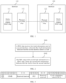
- FIG. 1 is a schematic diagram of an example application scenario according to an embodiment of this application.
- an interface 110 and an interface 120 may communicate with each other.
- the interface 110 includes a MAC chip 111 and a PHY chip 112, and the interface 120 includes a MAC chip 121 and a PHY chip 122.
- the interface 110 sends data to the interface 120, the data may be sent by the PHY chip 112 of the interface 110 to the PHY chip 122 of the interface 120.
- the interface 120 sends data to the interface 110, the data may be sent by the PHY chip 122 of the interface 120 to the PHY chip 112 of the interface 110.
- Both the interface 110 and the interface 120 may be Ethernet interfaces.
- both the interface 110 and the interface 120 include one PHY chip and one MAC chip.
- FIG. 1 is shown only for ease of understanding.
- Both the interface 110 and the interface 120 may include a plurality of PHY chips and a plurality of MAC chips.
- the interface 110 is used as an example.
- the interface 110 includes a plurality of PHY chips and a plurality of MAC chips
- the PHY chips are in one-to-one correspondence with the MAC chips.
- the MAC chip of the interface 110 and the PHY chip of the interface 110 may be connected through a media independent interface (media independent interface, MII), or may be connected through an attachment unit interface (Attachment Unit Interface, AUI).
- MII media independent interface
- AUI attachment unit interface
- the interface 110 includes a plurality of PHY chips and a plurality of MAC chips, and the MAC chips and the PHY chips may be connected through a universal slicing attachment unit interface (universal slicing AUI, USAUI), the plurality of MAC chips and the plurality of PHY chips are interconnected by using a serializer/deserializer (serializer/deserializer, SerDes).
- SerDes serializer/deserializer
- both the PHY chip 112 and the PHY chip 122 may include a physical coding sublayer (physical coding sublayer, PCS), a physical medium attachment (physical medium attachment, PMA) sublayer (sublayer), and a physical media dependent (physical media dependent, PMD) layer, details are not described herein.
- PCS physical coding sublayer
- PMA physical medium attachment sublayer
- PMD physical media dependent
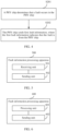
- FIG. 2 is a schematic flowchart of a fault information processing method according to an embodiment of this application.
- the method shown in FIG. 2 may be applied to a first interface, and the first interface may be, for example, an Ethernet interface.
- the first interface may include a PHY chip and a MAC chip.
- the first interface may be the interface 110 shown in the figure or the interface 120 shown in FIG. 1 .
- the method shown in FIG. 2 may be implemented by performing S101 and S102.
- the PHY chip receives first fault information sent by a second interface, where the first fault information indicates that the second interface detects a fault.
- the second interface is an interface communicating with the first interface.
- the first interface is the interface 110
- the second interface is the interface 120
- the first interface is the interface 120
- the second interface is the interface 110.
- the first fault information may be an RF.
- RF refer to a related description part of an institute of electrical and electronics engineers (institute of electrical and electronics engineers, IEEE) 802.3. Details are not described herein again.
- the PHY chip sends second fault information to the MAC chip, where the second fault information indicates that the fault is from the second interface.
- the PHY chip of the first interface may send the second fault information to the MAC chip of the first interface, where the second fault information indicates that the fault is from the second interface.
- the second fault information may be referred to as remote PHY fault (remote physical fault, RPF) information.
- the PHY chip of the first interface may send, to the MAC chip of the first interface, a data block carrying the second fault information, to send the second fault information to the MAC chip of the first interface.
- the data block is not specifically limited in this embodiment of this application.
- the data block may be similar to a data block used to transmit an LF and an RF.
- code corresponding to the second fault information may be defined, and the code corresponding to the second fault information is carried in the data block and sent to the MAC chip of the first interface.
- the code corresponding to the second fault information is not specifically limited in this embodiment of this application.
- code corresponding to the LF defined in IEEE 802.3 is /K28.4/D0.0/D0.0/D1.0/
- code corresponding to the RF defined in IEEE 802.3 is /K28.4/D0.0/D0.0/D2.0/
- the code corresponding to the second fault information may be /K28.4/D0.0/D0.0/D5.0/.
- the PHY chip of the first interface may include the second fault information in the overhead block and send the overhead block to the MAC chip of the first interface.
- the overhead block may include an indicator bit of the second fault information, and the indicator bit of the second fault information may be, for example, a reserved bit in the overhead block. For example, when a value of the bit is 0, it indicates that the overhead block does not carry the second fault information.
- FIG. 3 is a schematic diagram of a structure of an overhead block according to an embodiment of this application.
- the overhead block shown in FIG. 3 includes 64 bits, where bits 8 to 31 and bits 38 to 55 are reserved bits. In an example, one bit, for example, a bit 9, may be selected from reserved 40 bits as the indicator bit of the second fault information.
- Other fields in the overhead block shown in FIG. 3 are not described in detail herein.
- the first interface may include a plurality of PHY chips and a plurality of MAC chips, and each PHY chip of the first interface may perform the method shown in FIG. 2 .
- each PHY chip may correspond to an indicator bit of one piece of second fault information.
- the overhead block shown in FIG. 3 is still used as an example for description.
- one bit in the overhead block may be reserved for each PHY chip as the indicator bit of the second fault information.
- the first interface includes eight PHY chips. In this case, bits 8 to 15 shown in FIG. 3 may be used as indicator bits of second fault information corresponding to the eight PHY chips.
- the PHY chip of the first interface may send a control character sequence (control character sequence) to the MAC chip of the first interface, and include the second fault information in the control character sequence, to send the second fault information to the MAC chip of the first interface.
- the control character sequence may include 64 bits, that is, 8 bytes. Based on an existing special code block in 802.3, content of a byte, for example, the 4 th byte, may be self-defined to distinguish the second fault information from other information. For example, refer to the following Table 1 for understanding. Table 1 shows a control character sequence corresponding to the RPF information (namely, the second fault information).
- Table 1 is shown only for ease of understanding, and content of the byte 4 is not limited to 0x05 shown in Table 1.
- the PHY chip of the first interface may further send the first fault information to the MAC chip of the first interface.
- the PHY chip of the first interface transmits the first fault information to the MAC chip of the first interface. In this way, the MAC chip of the first interface may not only determine that the fault occurs in the second interface, but also determine that an interface detecting the fault is the second interface.
- the first interface can determine the specific location in which the fault occurs when receiving the first fault information.
- each PHY chip of the first interface can perform the foregoing S 101 and S102. Therefore, even if the first interface includes the plurality of PHY chips and the plurality of MAC chips, a specific PHY or MAC in which the fault occurs can be located.
- the MAC chip of the interface 120 may determine that a fault occurs in the MAC chip and/or the PHY chip that are/is in the interface 110 and that communicate/communicates with the PHY chip 122.
- the MAC chip of the first interface may report the second fault information to a controller, or send the second fault information to a main control chip of the first interface, and the main control chip reports the second fault information to a controller.
- Embodiments of this application further provides a fault information processing method. The following describes the method with reference to FIG. 4 .
- FIG. 4 is a schematic flowchart of another fault information processing method according to an embodiment of this application.
- the method shown in FIG. 4 may be applied to a first interface, and the first interface may be, for example, an Ethernet interface.
- the first interface may include a PHY chip and a MAC chip.
- the first interface may be the interface 110 shown in the figure or the interface 120 shown in FIG. 1 .
- the method shown in FIG. 4 may be implemented by performing S201 and S202.
- S201 The PHY chip determines that a fault occurs in the PHY chip.
- the PHY chip of the first interface may receive data sent by a first chip.
- a receiving fault occurring in the PHY chip may be that the PHY chip of the first interface fails to receive the data sent by the first chip.
- a fault when a fault occurs in a link from the first chip to the PHY chip, it may be determined that the fault occurs in the PHY chip of the first interface.
- S201 may be that the PHY chip determines that the fault occurs in the link from the first chip to the PHY chip.
- An implementation in which the PHY chip determines that the fault occurs in the link from the first chip to the PHY chip is not specifically limited in this embodiment of this application. In an example, if detecting a loss of signal (loss of signal), the PHY chip may determine that the fault occurs in the link from the first chip to the PHY chip.
- the PHY chip of the first interface may receive data sent by the MAC chip of the first interface or data sent by a PHY chip of a second interface communicating with the first interface
- the first chip may be the MAC chip of the first interface or the PHY chip of the second interface.
- S202 The PHY chip sends first fault information, where the first fault information indicates that the fault is from the PHY chip.
- the PHY chip when determining that the receiving fault occurs in the PHY chip, may send the first fault information indicating that the fault is from the PHY chip, so that a device or a chip receiving the first fault information determines that the fault occurs in the PHY chip of the first interface.
- the first fault information mentioned herein may be local PHY fault (local physical fault, LPF) information.
- the PHY chip of the first interface may send the first fault information to a controller, so that the controller learns that the fault occurs in the PHY chip of the first interface, and then takes a further measure.
- the PHY chip of the first interface may send the first fault information to the MAC chip of the first interface, so that the MAC chip of the first interface takes a further measure based on the first fault information.
- the MAC chip of the first interface changes data that originally needs to be sent to the PHY chip of the first interface to special data, such as an idle (Idle) code block, an error (Error) code block, an RF, all-zero data, or the like.
- the PHY chip of the first interface may send the first fault information to the MAC chip of the first interface in a plurality of implementations.
- the PHY chip of the first interface may send, to the MAC chip of the first interface, a data block carrying the first fault information, to send the first fault information to the MAC chip of the first interface.
- the data block is not specifically limited in this embodiment of this application.
- the data block may be similar to a data block used to transmit an LF and an RF.
- code corresponding to the first fault information may be defined, and the code corresponding to the first fault information is carried in the data block and sent to the MAC chip of the first interface.
- the code corresponding to the first fault information is not specifically limited in this embodiment of this application.
- the code corresponding to the first fault information may be /K28.4/D0.0/D0.0/D4.0/.
- Implementation 2 It is considered that if the PHY chip of the first interface and the MAC chip of the first interface are connected through a USAUI, an overhead block is communicated between the PHY chip of the first interface and the MAC chip of the first interface. Therefore, in an example, the PHY chip of the first interface may include the first fault information in the overhead block and send the overhead block to the MAC chip of the first interface.
- the overhead block may include an indicator bit of the first fault information, and the indicator bit of the first fault information may be, for example, a reserved bit in the overhead block. For example, when a value of the bit is 0, it indicates that the overhead block does not carry the first fault information. When a value of the bit is 1, it indicates that the overhead block carries the first fault information.
- bits 8 to 31 and the bits 38 to 55 in the overhead block shown in FIG. 3 are reserved bits.
- one bit may be selected from reserved 40 bits as the indicator bit of the first fault information.
- a bit 10 may be used as the indicator bit of the first fault information
- the bit 9 may be used as the indicator bit of the second fault information mentioned in S102.
- the first interface may include a plurality of PHY chips and a plurality of MAC chips, and each PHY chip of the first interface may perform the method shown in FIG. 4 .
- each PHY chip may correspond to an indicator bit of one piece of first fault information.
- the overhead block shown in FIG. 3 is still used as an example for description.
- one bit in the overhead block may be reserved for each PHY chip as the indicator bit of the second fault information.
- the first interface includes eight PHY chips. In this case, bits 16 to 23 shown in FIG. 3 may be used as indicator bits of first fault information corresponding to the eight PHY chips.
- the PHY chip of the first interface may send a control character sequence to the MAC chip of the first interface, and include the first fault information in the control character sequence, to send the first fault information to the MAC chip of the first interface.
- the control character sequence may include 64 bits, that is, 8 bytes. Content of a byte, for example, the 4 th byte, may be self-defined to distinguish the first fault information from other information. For example, refer to the following Table 2 for understanding. Table 2 shows a control character sequence corresponding to the LPF information (namely, the first fault information).
- 0x9C indicates that content of the 8 bytes is a control character sequence; and that content of the byte 3 is 0x04 indicates that the control character sequence is LPF information.
- Table 2 is shown only for ease of understanding, and content of the byte 4 is not limited to 0x04 shown in Table 2.
- the PHY chip of the first interface may further send second fault information to the second interface, where the second fault information indicates that the first interface detects the fault.
- the second fault information mentioned herein may be an RF.
- the PHY chip of the first interface communicates with the second interface via the PHY chip of the second interface. Therefore, the second fault information sent by the PHY chip of the first interface is received by the PHY chip of the second interface. After receiving the second fault information, the PHY chip of the second interface may further send, to a MAC chip of the second interface, fault information indicating that the fault is from the first interface. In this way, the second interface may determine that the fault is from the first interface.
- the first chip may be the MAC chip of the first interface or the PHY chip of the second interface.
- the PHY chip of the first interface may further send third fault information to the MAC chip of the first interface.
- the third fault information indicates that a chip other than the MAC chip of the first interface detects the fault.
- the third fault information mentioned herein may be an RF.
- the MAC chip of the first interface may take a further measure based on the third fault information.
- the MAC chip of the first interface changes data that originally needs to be sent to the PHY chip of the first interface to special data, such as an idle (Idle) code block, an error (Error) code block, an RF, all-zero data, or the like.
- special data such as an idle (Idle) code block, an error (Error) code block, an RF, all-zero data, or the like.
- the PHY chip of the first interface may send the first fault information and the third fault information to the MAC chip of the first interface by using same signaling.
- the PHY chip of the first interface may include the first fault information and the third fault information in a same packet and send the packet to the MAC chip of the first interface.
- the first interface may include both the first fault information and the third fault information in the overhead block and send the overhead block to the MAC chip of the first interface.
- the first interface may send a control character sequence that carries the first fault information and the third fault information to the MAC chip of the first interface.
- the PHY chip of the first interface may separately send the first fault information and the third fault information to the MAC chip of the first interface by using two different pieces of signaling.
- the third fault information is sent to the MAC chip of the first interface in a conventional RF sending manner.
- the conventional RF sending manner refer to a related description part of IEEE 802.3. Details are not described herein again.
- the PHY chip of the first interface may further send fourth fault information to the MAC chip of the first interface.
- the fourth fault information indicates that the first interface detects the fault.
- the fourth fault information mentioned herein may be an LF.
- the MAC chip of the first interface may take a further measure based on the fourth fault information, for example, send an RF to the PHY chip of the first interface, so that the PHY chip of the first interface transmits the RF to the PHY chip of the second interface.
- the PHY chip of the first interface may send the first fault information and the fourth fault information to the MAC chip of the first interface by using same signaling.
- the PHY chip of the first interface may include the first fault information and the fourth fault information in a same packet and send the packet to the MAC chip of the first interface.
- the first interface may include both the first fault information and the fourth fault information in the overhead block and send the overhead block to the MAC chip of the first interface.
- the first interface may send a control character sequence that carries the first fault information and the fourth fault information to the MAC chip of the first interface.
- the PHY chip of the first interface may separately send the first fault information and the fourth fault information to the MAC chip of the first interface by using two different pieces of signaling.
- the fourth fault information is sent to the MAC chip of the first interface in a conventional LF sending manner.
- the conventional LF sending manner refer to a related description part of IEEE 802.3. Details are not described herein again.
- the first fault information indicating a specific location of the fault may be sent. It can be learned that, according to this solution, the specific location of the fault can be determined.
- the MAC chip 111 detects a fault, and the MAC chip 110 sends an RF to the PHY chip 112.
- the PHY chip 112 transmits the RF to the PHY chip 122.
- the PHY chip 122 After receiving the RF, the PHY chip 122 sends an RPF and the RF to the MAC chip 121.
- the interface 120 is equivalent to the first interface in the method shown in FIG. 2
- the interface 110 is equivalent to the second interface in the method shown in FIG. 2
- the RF is equivalent to the first fault information in the method shown in FIG. 2
- the RPF is equivalent to the second fault information in the method shown in FIG. 2 .
- the PHY chip 112 determines that a fault occurs in a link from the MAC chip 111 to the PHY chip 112. In this case, the PHY chip 112 sends an RF and an LPF to the MAC chip 111. In addition, the PHY chip 112 sends an RF to the PHY chip 122. After receiving the RF, the PHY chip 122 sends the RF and an RPF to the MAC chip 121.
- the interface 110 is equivalent to the first interface in the method shown in FIG. 4
- the RF is equivalent to the third fault information in the method shown in FIG. 4
- the LPF is equivalent to the first fault information in the method shown in FIG. 4 .
- the interface 120 is equivalent to the first interface in the method shown in FIG. 2
- the RF is equivalent to the first fault information in the method shown in FIG. 2
- the RPF is equivalent to the second fault information in the method shown in FIG. 2 .
- the PHY chip 122 determines that a fault occurs in a link from the PHY chip 112 to the PHY chip 122. In this case, the PHY chip 122 sends an LF and an LPF to the MAC chip 121. In addition, the PHY chip 122 sends an RF to the PHY chip 112. After receiving the RF, the PHY chip 112 sends the RF and an RPF to the MAC chip 111.
- the interface 120 is equivalent to the first interface in the method shown in FIG. 4
- the LF is equivalent to the fourth fault information in the method shown in FIG. 4
- the LPF is equivalent to the first fault information in the method shown in FIG. 4 .
- the interface 110 is equivalent to the first interface in the method shown in FIG. 2
- the RF is equivalent to the first fault information in the method shown in FIG. 2
- the RPF is equivalent to the second fault information in the method shown in FIG. 2 .
- an embodiment of this application further provides a corresponding apparatus.
- FIG. 5 is a schematic diagram of a structure of a fault information processing apparatus according to an embodiment of this application.
- the fault information processing apparatus 500 shown in FIG. 5 may be used in a physical layer PHY chip of a first interface, and the first interface further includes a media access control MAC chip.
- the fault information processing apparatus 500 may be, for example, configured to perform the fault information processing method corresponding to FIG. 2 provided in the foregoing method embodiments.
- the fault information processing apparatus 500 may include, for example, a receiving unit 501 and a sending unit 502.
- the receiving unit 501 is configured to receive first fault information sent by a second interface, where the first fault information indicates that the second interface detects a fault.
- the sending unit 502 is configured to send second fault information to the MAC chip, where the second fault information indicates that the fault is from the second interface.
- the sending unit 502 is configured to send a data block to the MAC chip, where the data block includes the second fault information.
- the sending unit 502 is configured to send an overhead block to the MAC chip, where the overhead block includes the second fault information.
- the sending unit 502 is configured to send a control character sequence to the MAC chip, where the control character sequence includes the second fault information.
- the sending unit 502 is further configured to send the first fault information to the MAC chip.
- the apparatus 500 is an apparatus corresponding to the method corresponding to FIG. 1 provided in the foregoing method embodiments, and a specific implementation of each unit of the apparatus 500 has a same concept as the foregoing method embodiments. Therefore, for the specific implementation of each unit of the apparatus 500, refer to a description part of the foregoing method embodiments. Details are not described herein again.
- FIG. 6 is a schematic diagram of a structure of another fault information processing apparatus according to an embodiment of this application.
- the fault information processing apparatus 600 shown in FIG. 6 may be used in a physical layer PHY chip of a first interface, and the first interface further includes a media access control MAC chip.
- the fault information processing apparatus 600 may be, for example, configured to perform the fault information processing method corresponding to FIG. 4 provided in the foregoing method embodiments.
- the fault information processing apparatus 600 may include, for example, a processing unit 601 and a sending unit 602.
- the processing unit 601 is configured to determine that a fault occurs in the PHY chip.
- the sending unit 602 is configured to send first fault information, where the first fault information indicates that the fault is from the PHY chip.
- the processing unit 601 is configured to determine that a fault occurs in a link from a first chip to the PHY chip, where the first chip is the MAC chip of the first interface or a PHY chip of a second interface.
- the sending unit 602 is configured to send the first fault information to the MAC chip of the first interface and/or a controller.
- the sending unit 602 is further configured to send second fault information to the second interface, where the second fault information indicates that the first interface detects the fault.
- the sending unit 602 is further configured to send third fault information to the MAC chip of the first interface, where the third fault information indicates that a chip other than the MAC chip of the first interface detects the fault.
- the sending unit 602 is further configured to send fourth fault information to the MAC chip of the first interface, where the fourth fault information indicates that the first interface detects the fault.
- the apparatus 600 is an apparatus corresponding to the method corresponding to FIG. 4 provided in the foregoing method embodiments, and a specific implementation of each unit of the apparatus 600 has a same concept as the foregoing method embodiments. Therefore, for the specific implementation of each unit of the apparatus 600, refer to a description part of the foregoing method embodiments. Details are not described herein again.
- FIG. 7 is a schematic diagram of a structure of a device according to an embodiment of this application.
- the device 700 includes a processor 710, a communication interface 720, and a memory 730.
- the device 700 may include one or more processors 710.
- one processor is used as an example.
- the processor 710, the communication interface 720, and the memory 730 may be connected by using a bus system or in another manner.
- the processor 710, the communication interface 720, and the memory 730 are connected by using a bus system 740.
- the processor 710 may be a central processing unit (central processing unit, CPU), a network processor (network processor, NP), or a combination of a CPU and an NP.
- the processor 710 may further include a hardware chip.
- the hardware chip may be an application-specific integrated circuit (application-specific integrated circuit, ASIC), a programmable logic device (programmable logic device, PLD), or a combination thereof.
- the PLD may be a complex programmable logic device (complex programmable logic device, CPLD), a field-programmable gate array (field-programmable gate array, FPGA), a generic array logic (generic array logic, GAL), or any combination thereof.
- the memory 730 may include a volatile memory (English: volatile memory), for example, a random access memory (random access memory, RAM).
- the memory 730 may include a non-volatile memory (English: non-volatile memory), for example, a flash memory (English: flash memory), a hard disk drive (hard disk drive, HDD), or a solid-state drive (solid-state drive, SSD).
- the memory 730 may alternatively include a combination of the foregoing types of memories.
- the memory 730 may store, for example, the first fault information mentioned in S 101.
- the memory 730 may store, for example, the first fault information in S202.
- the memory 730 stores an operating system and a program, an executable module or a data structure, or a subset thereof, or an extended set thereof, where the program may include various operating instructions to implement various operations.
- the operating system may include various system programs, to implement various basic services and process a hardware-based task.
- the processor 710 may read the program stored in the memory 730, to implement the fault information processing methods provided in embodiments of this application.
- the bus system 740 may be a peripheral component interconnect (peripheral component interconnect, PCI) bus, an extended industry standard architecture (extended industry standard architecture, EISA) bus, or the like.
- PCI peripheral component interconnect
- EISA extended industry standard architecture
- the bus system 740 may be classified into an address bus, a data bus, a control bus, and the like. For ease of representation, only one bold line is used for representation in FIG. 7 , but this does not mean that there is only one bus or only one type of bus.
- An embodiment of this application further provides a computer-readable storage medium, including instructions or a computer program.
- the instructions When the instructions are run or the computer program is run on a computer, the computer is enabled to perform the fault information processing methods provided in the foregoing embodiments.
- An embodiment of this application further provides a computer program product including instructions or a computer program.
- the computer program product runs on a computer, the computer is enabled to perform the fault information processing methods provided in the foregoing embodiments.
- the apparatus in this application may be a network device such as a switch or a router, may be a server, or may be a part of a network device or a server such as a chip on the network device.
- the apparatus in this application may alternatively be a function module deployed in a device or a network.
- the disclosed system, apparatus, and method may be implemented in other manners.
- the described apparatus embodiments are merely examples.
- division into the units is merely logical service division.
- a plurality of units or parts may be combined or integrated into another system, or some features may be ignored or not performed.
- the displayed or discussed mutual couplings or direct couplings or communication connections may be implemented through some interfaces.
- the indirect couplings or communication connections between the apparatus or units may be implemented in electronic, mechanical, or other forms.
- the units described as separate components may or may not be physically separate, and components displayed as units may or may not be physical units, in other words, may be located in one location, or may be distributed on a plurality of network units. Some or all of the units may be selected based on actual requirements to achieve the objectives of the solutions of embodiments.
- service units in embodiments of this application may be integrated into one processing unit, or each unit may exist alone physically, or two or more units may be integrated into one unit.
- the integrated unit may be implemented in a form of hardware, or may be implemented in a form of a software service unit.
- the integrated unit When the integrated unit is implemented in the form of the software service unit and sold or used as an independent product, the integrated unit may be stored in a computer-readable storage medium.
- the computer software product is stored in a storage medium and includes several instructions for instructing a computer device (which may be a personal computer, a server, or a network device) to perform all or some of the steps of the methods described in embodiments of this application.
- the storage medium includes any medium that can store program code, such as a USB flash drive, a removable hard disk, a read-only memory (ROM, Read-Only Memory), a random access memory (RAM, Random Access Memory), a magnetic disk, or an optical disc.
- services described in the present invention may be implemented by hardware, software, firmware, or any combination thereof.
- these services may be stored in a computer-readable medium or transmitted as one or more instructions or code on the computer-readable medium.
- the computer-readable medium includes a computer storage medium and a communication medium, where the communication medium includes any medium that enables a computer program to be transmitted from one place to another.
- the storage medium may be any available medium accessible to a general-purpose or a dedicated computer.
Landscapes
- Engineering & Computer Science (AREA)
- General Engineering & Computer Science (AREA)
- Theoretical Computer Science (AREA)
- Computer Networks & Wireless Communication (AREA)
- Signal Processing (AREA)
- Computer Hardware Design (AREA)
- Quality & Reliability (AREA)
- Physics & Mathematics (AREA)
- General Physics & Mathematics (AREA)
- Environmental & Geological Engineering (AREA)
- Small-Scale Networks (AREA)
Applications Claiming Priority (2)
| Application Number | Priority Date | Filing Date | Title |
|---|---|---|---|
| CN202111275477.7A CN116069568A (zh) | 2021-10-29 | 2021-10-29 | 一种故障信息处理方法及装置 |
| PCT/CN2022/092584 WO2023071145A1 (fr) | 2021-10-29 | 2022-05-13 | Procédé et appareil de traitement d'informations de défaut |
Publications (2)
| Publication Number | Publication Date |
|---|---|
| EP4414846A1 true EP4414846A1 (fr) | 2024-08-14 |
| EP4414846A4 EP4414846A4 (fr) | 2025-02-26 |
Family
ID=86160459
Family Applications (1)
| Application Number | Title | Priority Date | Filing Date |
|---|---|---|---|
| EP22885058.2A Pending EP4414846A4 (fr) | 2021-10-29 | 2022-05-13 | Procédé et appareil de traitement d'informations de défaut |
Country Status (4)
| Country | Link |
|---|---|
| US (1) | US20240283695A1 (fr) |
| EP (1) | EP4414846A4 (fr) |
| CN (1) | CN116069568A (fr) |
| WO (1) | WO2023071145A1 (fr) |
Family Cites Families (14)
| Publication number | Priority date | Publication date | Assignee | Title |
|---|---|---|---|---|
| US6839345B2 (en) * | 1999-12-17 | 2005-01-04 | Texas Instruments Incorporated | MAC/PHY interface |
| JP2003324463A (ja) * | 2002-04-26 | 2003-11-14 | Mitsubishi Electric Corp | 通信経路切替装置 |
| US7020729B2 (en) * | 2002-05-16 | 2006-03-28 | Intel Corporation | Protocol independent data transmission interface |
| TWI221560B (en) * | 2003-04-07 | 2004-10-01 | Via Tech Inc | Integrated reduced media independent interface |
| US7924863B2 (en) * | 2007-01-10 | 2011-04-12 | Etherntty Networks Ltd. | Device and method for processing data chunks |
| CN101986604B (zh) * | 2010-10-29 | 2015-01-28 | 中兴通讯股份有限公司 | 分组传送网的链路故障定位方法及系统 |
| US8902925B2 (en) * | 2012-05-01 | 2014-12-02 | Texas Instruments Incorporated | Forward error correction decoder |
| US9401803B2 (en) * | 2012-10-25 | 2016-07-26 | Texas Instruments Incorporated | Flexible scrambler/descrambler architecture for a transceiver |
| CN102970169B (zh) * | 2012-11-30 | 2015-11-25 | 福建星网锐捷网络有限公司 | 设备端口故障检测及定位方法和系统 |
| CN109391494B (zh) * | 2017-08-09 | 2021-02-09 | 华为技术有限公司 | 一种通信方法、设备及可读存储介质 |
| US20200072889A1 (en) * | 2018-09-05 | 2020-03-05 | Nxp B.V. | Physical layer device and method for performing physical layer operations in a communications network |
| CN111585779B (zh) * | 2019-02-19 | 2021-10-15 | 华为技术有限公司 | 一种灵活以太网通信方法及网络设备 |
| CN111585778B (zh) * | 2019-02-19 | 2022-02-25 | 华为技术有限公司 | 一种灵活以太网通信方法及网络设备 |
| US11290223B1 (en) * | 2019-06-25 | 2022-03-29 | Marvell Asia Pte Ltd | Physical layer (PHY) data unit encoding for hybrid automatic repeat request (HARQ) transmission |
-
2021
- 2021-10-29 CN CN202111275477.7A patent/CN116069568A/zh active Pending
-
2022
- 2022-05-13 EP EP22885058.2A patent/EP4414846A4/fr active Pending
- 2022-05-13 WO PCT/CN2022/092584 patent/WO2023071145A1/fr not_active Ceased
-
2024
- 2024-04-29 US US18/649,140 patent/US20240283695A1/en active Pending
Also Published As
| Publication number | Publication date |
|---|---|
| EP4414846A4 (fr) | 2025-02-26 |
| US20240283695A1 (en) | 2024-08-22 |
| WO2023071145A1 (fr) | 2023-05-04 |
| CN116069568A (zh) | 2023-05-05 |
Similar Documents
| Publication | Publication Date | Title |
|---|---|---|
| US10528410B2 (en) | Apparatus, method and system to exchange error information in a unified protocol communication | |
| US7844866B2 (en) | Mechanism to report operating system events on an intelligent platform management interface compliant server | |
| US10636577B2 (en) | Safe handling of link errors in a peripheral component interconnect express (PCIE) device | |
| US10341020B2 (en) | Flexible ethernet logical lane aggregation | |
| EP4080839B1 (fr) | Procédé et appareil de transmission de données à base de pcie | |
| US12526351B2 (en) | PCIe-based data transmission method and apparatus | |
| WO2019233386A1 (fr) | Procédé et dispositif de communication en réseau | |
| US7502369B2 (en) | High speed interface systems and methods | |
| US20050207360A1 (en) | Configuring a transmission mode between devices | |
| US10069604B2 (en) | Data transmission method and apparatus | |
| EP4459474A1 (fr) | Procédé et appareil de transmission de données, ainsi que dispositif et support | |
| US10313222B2 (en) | Diagnosis of a network adapter during network operation | |
| US20170093521A1 (en) | System and Method of Selective Encoding for Enhanced Serializer/Deserializer Throughput | |
| US20240223684A1 (en) | Auto-negotiation method and apparatus | |
| KR20200037368A (ko) | 통신 방법, 통신 장치 및 저장 매체 | |
| US20240248819A1 (en) | Peripheral component interconnect express device and operating method thereof | |
| US20250068503A1 (en) | Circuit for status monitoring, and fault recovery and isolation for inter-integrated circuit (i2c) bus, and method implemented by the same | |
| US20240283695A1 (en) | Fault Information Processing Method and Apparatus | |
| CN111930582B (zh) | 系统管理总线检测平台、处理器及系统管理总线检测方法 | |
| US9710420B2 (en) | System and method for improving the efficiency of a serial interface protocol | |
| CN111263250B (zh) | 业务数据处理方法及设备 | |
| CN112732602B (zh) | 电子装置、网络交换器以及中断传输与接收方法 | |
| EP4531361A1 (fr) | Procédé et appareil de négociation de mode, dispositif, système et support d'enregistrement lisible par ordinateur | |
| EP4336752A1 (fr) | Procédé, appareil et système de transmission de données, et support de stockage lisible par ordinateur | |
| EP4064572B1 (fr) | Procédé et appareil de traitement de données |
Legal Events
| Date | Code | Title | Description |
|---|---|---|---|
| STAA | Information on the status of an ep patent application or granted ep patent |
Free format text: STATUS: THE INTERNATIONAL PUBLICATION HAS BEEN MADE |
|
| PUAI | Public reference made under article 153(3) epc to a published international application that has entered the european phase |
Free format text: ORIGINAL CODE: 0009012 |
|
| STAA | Information on the status of an ep patent application or granted ep patent |
Free format text: STATUS: REQUEST FOR EXAMINATION WAS MADE |
|
| 17P | Request for examination filed |
Effective date: 20240508 |
|
| AK | Designated contracting states |
Kind code of ref document: A1 Designated state(s): AL AT BE BG CH CY CZ DE DK EE ES FI FR GB GR HR HU IE IS IT LI LT LU LV MC MK MT NL NO PL PT RO RS SE SI SK SM TR |
|
| REG | Reference to a national code |
Ref country code: DE Ref legal event code: R079 Free format text: PREVIOUS MAIN CLASS: G06F0011220000 Ipc: H04L0043081700 |
|
| DAV | Request for validation of the european patent (deleted) | ||
| DAX | Request for extension of the european patent (deleted) | ||
| A4 | Supplementary search report drawn up and despatched |
Effective date: 20250123 |
|
| RIC1 | Information provided on ipc code assigned before grant |
Ipc: H04L 41/0654 20220101ALN20250117BHEP Ipc: G06F 11/22 20060101ALI20250117BHEP Ipc: H04L 41/0677 20220101ALI20250117BHEP Ipc: H04L 43/065 20220101ALI20250117BHEP Ipc: H04L 43/0823 20220101ALI20250117BHEP Ipc: H04L 43/0817 20220101AFI20250117BHEP |
|
| STAA | Information on the status of an ep patent application or granted ep patent |
Free format text: STATUS: EXAMINATION IS IN PROGRESS |