EP4414961A1 - Systeme, vorrichtungen und verfahren zur synchronisierung von daten aus asynchronen quellen - Google Patents
Systeme, vorrichtungen und verfahren zur synchronisierung von daten aus asynchronen quellen Download PDFInfo
- Publication number
- EP4414961A1 EP4414961A1 EP24151341.5A EP24151341A EP4414961A1 EP 4414961 A1 EP4414961 A1 EP 4414961A1 EP 24151341 A EP24151341 A EP 24151341A EP 4414961 A1 EP4414961 A1 EP 4414961A1
- Authority
- EP
- European Patent Office
- Prior art keywords
- data
- telematic
- input
- point
- points
- Prior art date
- Legal status (The legal status is an assumption and is not a legal conclusion. Google has not performed a legal analysis and makes no representation as to the accuracy of the status listed.)
- Pending
Links
Images



Classifications
-
- G—PHYSICS
- G08—SIGNALLING
- G08G—TRAFFIC CONTROL SYSTEMS
- G08G1/00—Traffic control systems for road vehicles
- G08G1/01—Detecting movement of traffic to be counted or controlled
- G08G1/0104—Measuring and analyzing of parameters relative to traffic conditions
- G08G1/0108—Measuring and analyzing of parameters relative to traffic conditions based on the source of data
- G08G1/0112—Measuring and analyzing of parameters relative to traffic conditions based on the source of data from the vehicle, e.g. floating car data [FCD]
-
- H—ELECTRICITY
- H04—ELECTRIC COMMUNICATION TECHNIQUE
- H04N—PICTORIAL COMMUNICATION, e.g. TELEVISION
- H04N7/00—Television systems
- H04N7/01—Conversion of standards, e.g. involving analogue television standards or digital television standards processed at pixel level
- H04N7/0127—Conversion of standards, e.g. involving analogue television standards or digital television standards processed at pixel level by changing the field or frame frequency of the incoming video signal, e.g. frame rate converter
-
- G—PHYSICS
- G08—SIGNALLING
- G08G—TRAFFIC CONTROL SYSTEMS
- G08G1/00—Traffic control systems for road vehicles
- G08G1/01—Detecting movement of traffic to be counted or controlled
- G08G1/0104—Measuring and analyzing of parameters relative to traffic conditions
- G08G1/0125—Traffic data processing
-
- G—PHYSICS
- G08—SIGNALLING
- G08G—TRAFFIC CONTROL SYSTEMS
- G08G1/00—Traffic control systems for road vehicles
- G08G1/01—Detecting movement of traffic to be counted or controlled
- G08G1/0104—Measuring and analyzing of parameters relative to traffic conditions
- G08G1/0137—Measuring and analyzing of parameters relative to traffic conditions for specific applications
- G08G1/0141—Measuring and analyzing of parameters relative to traffic conditions for specific applications for traffic information dissemination
-
- H—ELECTRICITY
- H04—ELECTRIC COMMUNICATION TECHNIQUE
- H04N—PICTORIAL COMMUNICATION, e.g. TELEVISION
- H04N7/00—Television systems
- H04N7/01—Conversion of standards, e.g. involving analogue television standards or digital television standards processed at pixel level
- H04N7/0135—Conversion of standards, e.g. involving analogue television standards or digital television standards processed at pixel level involving interpolation processes
-
- H—ELECTRICITY
- H03—ELECTRONIC CIRCUITRY
- H03M—CODING; DECODING; CODE CONVERSION IN GENERAL
- H03M7/00—Conversion of a code where information is represented by a given sequence or number of digits to a code where the same, similar or subset of information is represented by a different sequence or number of digits
- H03M7/30—Compression; Expansion; Suppression of unnecessary data, e.g. redundancy reduction
- H03M7/3059—Digital compression and data reduction techniques where the original information is represented by a subset or similar information, e.g. lossy compression
-
- H—ELECTRICITY
- H03—ELECTRONIC CIRCUITRY
- H03M—CODING; DECODING; CODE CONVERSION IN GENERAL
- H03M7/00—Conversion of a code where information is represented by a given sequence or number of digits to a code where the same, similar or subset of information is represented by a different sequence or number of digits
- H03M7/30—Compression; Expansion; Suppression of unnecessary data, e.g. redundancy reduction
- H03M7/70—Type of the data to be coded, other than image and sound
Definitions
- the present disclosure generally relates to systems, devices, and methods for synchronizing data, and in particular relates to synchronizing data from asynchronous sources.
- Sensors have been developed which collect a variety of data during operation of vehicles. However, such sensors do not necessarily collect data at the same rate, and thus data from multiple sensors may not be synchronized. It is desirable to provide a means for synchronizing data from multiple asynchronous data sources.
- the present disclosure describes a method for synchronizing data, the method comprising: accessing input video data of a first data rate and input telematic data of at least a second data rate different from the first data rate; receiving an indication of a synchronized data rate; generating reduced telematic data, by selecting data points from the input telematic data for inclusion in the reduced telematic data, based on differences of the data points to iteratively-defined reference lines defined through portions of the input telematic data; generating interpolated video data by interpolating the input video data at the synchronized data rate for a threshold time period around each identified data point in the input telematic data; generating interpolated telematic data by interpolating the reduced telematic data at the synchronized data rate for the threshold time period around each identified data point in the input telematic data; and sampling the interpolated telematic data and the interpolated video data at the sample rate in the threshold time period.
- Selecting data points from the input telematic data for inclusion in the reduced telematic data, based on differences of the data points to iteratively-defined reference lines defined through portions of the input telematic data, may comprise, for each data point of the input telematic data: determining a minimum difference between the data point and a corresponding reference line of the iteratively-defined reference lines, where the data point is included in the reduced telematic data if the minimum difference between the data point and the corresponding reference line exceeds a difference threshold.
- Selecting data points from the input telematic data for inclusion in the reduced telematic data, based on differences of the data points to iteratively-defined reference lines defined through portions of the input telematic data may comprise: defining a reference line through the input telematic data; identifying a data point of the input telematic data, where a minimum difference between the data point and the reference line is greater than a minimum difference between other data points and the reference line; and if the minimum difference between the data point and the reference line exceeds a difference threshold: selecting the data point for inclusion in the reduced telematic data; and defining new reference lines which intersect the sample point through the input telematic data.
- Selecting data points from the input telematic data for inclusion in the reduced telematic data may further comprise: defining an additional reference line through the input telematic data which intersects a data point previously selected for inclusion in the reduced telematic data; identifying an additional data point of the input telematic data, where a minimum difference between the additional data point and the additional reference line is greater than a minimum difference between other data points and the additional reference line; and if the minimum difference between the additional data point and the additional reference line exceeds the difference threshold: select the additional data point for inclusion in the reduced telematic data.
- the input telematic data may include location data for a vehicle, and selecting data points from the input telematic data for inclusion in the reduced telematic data, based on differences of the data points to iteratively-defined reference lines defined through portions of the input telematic data may comprise: selecting data points from the input telematic data for inclusion in the reduced telematic data, based on physical distances between positions represented by the data points to iteratively-defined reference lines defined through portions of the location data.
- the input telematic data may include speed data for a vehicle, and selecting data points from the input telematic data for inclusion in the reduced telematic data, based on differences of the data points to iteratively-defined reference lines defined through portions of the input telematic data may comprise: selecting data points from the input telematic data for inclusion in the reduced telematic data, based on differences in speed between speeds represented by the data points to iteratively-defined reference lines defined through portions of the speed data.
- the input telematic data may include acceleration data for a vehicle, and selecting data points from the input telematic data for inclusion in the reduced telematic data, based on differences of the data points to iteratively-defined reference lines defined through portions of the input telematic data may comprise: selecting data points from the input telematic data for inclusion in the reduced telematic data, based on differences in acceleration between accelerations represented by the data points to iteratively-defined reference lines defined through portions of the acceleration data.
- the method may further comprise receiving an indication of the threshold time period.
- the present disclosure describes a system for synchronizing data, the system comprising: at least one processor; at least one non-transitory processor-readable storage medium communicatively coupled to the at least one processor and storing processor-executable instructions which when executed by the at least one processor cause the system to: access, by the at least one processor, input video data of a first data rate and input telematic data of at least a second data rate different from the first data rate; receiving, by the at least one processor, an indication of a synchronized data rate; generate, by the at least one processor, reduced telematic data, by selecting data points from the input telematic data for inclusion in the reduced telematic data, based on differences of the data points to iteratively-defined reference lines defined through portions of the input telematic data; generate, by the at least one processor, interpolated video data by interpolating the input video data at the synchronized data rate for a threshold time period around each identified data point in the input telematic data; generate, by the at least one processor
- the processor-executable instructions which cause the at least one processor to select data points from the input telematic data for inclusion in the reduced telematic data, based on differences of the data points to iteratively-defined reference lines defined through portions of the input telematic data, may cause the at least one processor to, for each data point of the input telematic data: determine a minimum difference between the data point and a corresponding reference line of the iteratively-defined reference lines, where the data point is included in the reduced telematic data if the minimum difference between the data point and the corresponding reference line exceeds a difference threshold.
- the processor-executable instructions which cause the at least one processor to select data points from the input telematic data for inclusion in the reduced telematic data, based on differences of the data points to iteratively-defined reference lines defined through portions of the input telematic data, may cause the at least one processor to: define a reference line through the input telematic data; identify a data point of the input telematic data, where a minimum difference between the data point and the reference line is greater than a minimum difference between other data points and the reference line; and if the minimum difference between the data point and the reference line exceeds a difference threshold: select the data point for inclusion in the reduced telematic data; and define new reference lines which intersect the sample point through the input telematic data.
- the processor-executable instructions which cause the at least one processor to select data points from the input telematic data for inclusion in the reduced telematic data, based on differences of the data points to iteratively-defined reference lines defined through portions of the input telematic data, may further cause the at least one processor to: define an additional reference line through the input telematic data which intersects a data point previously selected for inclusion in the reduced telematic data; identify an additional data point of the input telematic data, where a minimum difference between the additional data point and the additional reference line is greater than a minimum difference between other data points and the additional reference line; and if the minimum difference between the additional data point and the additional reference line exceeds the difference threshold: select the additional data point for inclusion in the reduced telematic data.
- the input telematic data may include location data for a vehicle, and the processor-executable instructions which cause the at least one processor to select data points from the input telematic data for inclusion in the reduced telematic data, based on differences of the data points to iteratively-defined reference lines defined through portions of the input telematic data, may cause the at least one processor to: select data points from the input telematic data for inclusion in the reduced telematic data, based on physical distances between positions represented by the data points to iteratively-defined reference lines defined through portions of the location data.
- the input telematic data may include speed data for a vehicle, and the processor-executable instructions which cause the at least one processor to select data points from the input telematic data for inclusion in the reduced telematic data, based on differences of the data points to iteratively-defined reference lines defined through portions of the input telematic data, may cause the at least one processor to: select data points from the input telematic data for inclusion in the reduced telematic data, based on differences in speed between speeds represented by the data points to iteratively-defined reference lines defined through portions of the speed data.
- the input telematic data may include acceleration data for a vehicle, and the processor-executable instructions which cause the at least one processor to select data points from the input telematic data for inclusion in the reduced telematic data, based on differences of the data points to iteratively-defined reference lines defined through portions of the input telematic data, cause the at least one processor to: select data points from the input telematic data for inclusion in the reduced telematic data, based on differences in acceleration between accelerations represented by the data points to iteratively-defined reference lines defined through portions of the acceleration data.
- the system may further comprise a user input device for receiving an indication of the threshold time period.
- the present disclosure details systems, methods, and devices for synchronizing data from multiple sensors.
- the present disclosure sees particular value in telematics, where telematic data regarding operation of a vehicle or plurality of vehicles is collected.
- a telematics system monitors a vehicle using an onboard telematic monitoring device for gathering and transmitting vehicle operation information. For instance, fleet managers can employ telematics to have remote access to real time operation information of each vehicle in a fleet.
- a vehicle may include a car, truck, recreational vehicle, heavy equipment, tractor, snowmobile or other transportation asset.
- a telematic monitoring device may detect environmental operating conditions associated with a vehicle, for example, outside temperature, attachment status of an attached trailer, and temperature inside an attached refrigeration trailer.
- a telematic monitoring device may also detect operating conditions of an associated vehicle, such as position, (e.g., geographic coordinates), speed, and acceleration, time of day of operation, distance traveled, stop duration, customer location, idling duration, driving duration, among others.
- position e.g., geographic coordinates
- speed e.g., speed
- acceleration time of day of operation
- distance traveled e.g., distance traveled
- stop duration e.g., customer location
- idling duration e.g., driving duration
- driving duration e.g., driving duration, among others.
- the telematic monitoring device collects and transmits data to the telematics system that is representative of the vehicle operation and usage execution. This data may be collected over a time period of sufficient duration to allow for pattern recognition of the vehicle's operation.
- the duration may be determined to be a number of days between 30 days and 90 days, though in practice any appropriate number of days could be implemented as the duration.
- raw vehicle data is transmitted from an onboard telematic monitoring device to a remote subsystem, (e.g., data management system which may comprise a cloud system or a management system).
- Raw vehicle data may include information indicating the identity of the onboard telematic monitoring device (e.g., device identifier, device ID) and/or the identity of the associated vehicle the onboard telematic monitoring device is aboard.
- Specific and non-limiting examples of raw vehicle data includes device ID data, position data, speed data, ignition state data, (e.g. indicates whether vehicle ignition is ON or OFF), and datetime data indicative of a date and time vehicle operating conditions were logged by the telematic monitoring device.
- Raw vehicle data transmitted and collected over a period of time forms historical vehicle data which may be stored by the remote subsystem for future analysis of a single vehicle or fleet performance.
- a single fleet may comprise many vehicles, and thus large volumes of raw vehicle data (e.g., terabytes, petabytes, exabytes ...) may be transmitted to, and stored by, a remote subsystem.
- vehicle data collected, processed, and/or transmitted by a telematics monitoring device can be broadly included in "telematic data", among other types of data such as location data discussed later.
- telematic data quantity is reduced prior to processing, transmission, or storage, to reduce resource burden.
- processing burden for interpolating said data is reduced since there is less data to interpolate.
- transmission and/or storage burden is reduced, since there is less data to transmit and/or store.
- a telematic monitoring device can have at least one processing unit thereon which processes or filters raw vehicle data, and transmits processed or filtered data.
- Such systems can reduce the bandwidth required for transmission and required storage capacity for transmitted data.
- telematics systems have resulted in improved performance and maintenance of vehicles in the fleet. Additionally, data from telematics systems can also be useful to analyze traffic, to provide information for infrastructure design, planning, and implementation.
- Telematics system 100 comprises telematics subsystem 102 having a first network interface 108 and onboard telematic monitoring devices 104 of vehicles 114 communicatively coupled therewith via communication network 110.
- the telematics subsystem 102 in an implementation comprises a management system which is a managed cloud data warehouse for performing analytics on data stored therein.
- the management system may comprise a plurality of management systems, datastores, and other devices, configured in a centralized, distributed or other arrangement.
- one or more different management systems may be employed and configured separately or in a centralized, distributed or other arrangement.
- telematics subsystems 102 includes at least one non-transitory processor-readable storage medium 120 and at least one processor 122.
- the at least one non-transitory processor-readable storage medium 120 can store data on which analytics is performed, and/or can store instructions thereon. Said instructions, when executed by the at least one processor 122, cause the telematics subsystem to perform the desired operations, analysis, or data collection/aggregation.
- Communication network 110 may include one or more computing systems and may be any suitable combination of networks or portions thereof to facilitate communication between network components. Some examples of networks include, Wide Area Networks (WANs), Local Area Networks (LANs), Wireless Wide Area Networks (WWANs), data networks, cellular networks, voice networks, among other networks, which may be wired and/or wireless. Communication network 110 may operate according to one or more communication protocols, such as, General Packet Radio Service (GPRS), Universal Mobile Telecommunications Service (UMTS), GSM, Enhanced Data Rates for GSM Evolution (EDGE), LTE, CDMA, LPWAN, Wi-Fi TM , Bluetooth TM , Ethernet, HTTP/S, TCP, and CoAP/DTLS, or other suitable protocol. Communication network 110 may take other forms as well.
- GPRS General Packet Radio Service
- UMTS Universal Mobile Telecommunications Service
- GSM Global System for Mobile Communications
- EDGE Enhanced Data Rates for GSM Evolution
- LTE Long Term Evolution
- CDMA Code Division Multiple Access
- Telematics system 100 may comprise another network interface 109 for communicatively coupling to another communication network 112.
- communication network 112 may comprise a communication gateway between the fleet owners and the telematics system 100.
- a vehicle may include a car, truck, recreational vehicle, heavy equipment, tractor, snowmobile, or other transportation asset.
- Onboard telematic monitoring devices 104 may transmit raw vehicle data associated with vehicles 114 through the communication network 110 to the telematics subsystem 102.
- a telematics system may comprise many vehicles 114, such as hundreds, thousands and tens of thousands or more. Thus, huge volumes of raw vehicle data may be received and stored by remote telematics subsystem 102.
- sensing modules configured for sensing and/or measuring a physical property that may indicate an operating condition of a vehicle.
- sensing modules may sense and/or measure a vehicle's position, (e.g., GPS coordinates), speed, direction, rates of acceleration or deceleration, for instance, along the x-axis, y-axis, and/or z-axis, altitude, orientation, movement in the x, y, and/or z direction, ignition state, transmission and engine performance, and times of operation among others.
- Telematic monitoring device 104 may comprise a sensing module for determining vehicle position.
- the sensing module may utilize Global Positioning System (GPS) technology (e.g., GPS receiver) for determining the geographic position (Lat/Long coordinates) of vehicle 114.
- GPS Global Positioning System
- the sensing module utilizes another a global navigation satellite system (GNSS) technology, such as, GLONASS or BeiDou.
- GNSS global navigation satellite system
- the sensing module may further utilize another kind of technology for determining geographic position.
- the sensing module may provide other vehicle operating information, such as speed.
- the telematic monitoring device 104 may communicate with a plurality of sensing modules for a vehicle.
- vehicle position information may be provided according to another geographic coordinate system, such as, Universal Transverse Mercator, Military Grid Reference System, or United States National Grid.
- a vehicle 114 may include various control, monitoring and/or sensor modules for detecting vehicle operating conditions. Some specific and non-limiting examples include, an engine control unit (ECU), a suspension and stability control module, a headlamp control module, a windscreen wiper control module, an anti-lock braking system module, a transmission control module, and a braking module.
- a vehicle may have any combination of control, monitoring and/or sensor modules.
- a vehicle may include a data/communication bus accessible for monitoring vehicle operating information, provided by one or more vehicle control, monitoring and/or sensor modules.
- a vehicle data/communication bus may operate according to an established data bus protocol, such as the Controller Area Network bus (CAN-bus) protocol that is widely used in the automotive industry for implementing a distributed communications network.
- Specific and non-limiting examples of vehicle operation information provided by vehicle monitoring and/or sensor modules include, ignition state, fuel tank level, intake air temp, and engine RPM among others.
- CAN-bus Controller Area Network bus
- Telematic monitoring device 104 may comprise a monitoring module operable to communicate with a data/communication bus of vehicle 114.
- the monitoring module may communicate via a direct connection, such as, electrically coupling, with a data/communication bus of vehicle 114 via a vehicle communication port, (e.g., diagnostic port/communication bus, OBDII port).
- the monitoring module may comprise a wireless communication interface for communicating with a wireless interface of the data/communication bus of vehicle 114.
- a monitoring module may communicate with other external devices/systems that detect operating conditions of the vehicle.
- Telematic monitoring device 104 may be configured to wirelessly communicate with telematics subsystem 102 via a wireless communication module. In some embodiments, telematic monitoring device 104 may directly communicate with one or more networks outside vehicle 114 to transmit data (such as telematic data) to telematics subsystem 102.
- data such as telematic data
- a person of ordinary skill will recognize that functionality of some modules may be implemented in one or more devices and/or that functionality of some modules may be integrated into the same device.
- Telematic monitoring devices 104 may transmit raw vehicle data (or telematic data), indicative of vehicle operation information collected thereby, to telematics subsystem 102.
- the raw vehicle data may be transmitted at predetermined time intervals, (e.g. heartbeat), intermittently, and/or according to other predefined conditions.
- Raw vehicle data (or telematic data) transmitted from telematic monitoring devices 104 may include information indicative of device ID, position, speed, ignition state, and date and time operating conditions are logged, for instance, in an onboard datastore.
- raw vehicle data may comprise data indicative of numerous other vehicle operating conditions.
- Raw vehicle data may be transmitted from a monitoring device when a vehicle is moving, stationary, and during both ON and OFF ignition states.
- image sensors 134 each aboard a respective vehicle 104.
- Each of image sensor 134 could for example be a camera, such as a video camera.
- Such image sensors capture image data (or video data, as a sequence of images) in a field of view of the respective image sensor.
- an image sensor is positioned and oriented to capture image data representing a field of view outside the vehicle (e.g. a dash cam, rear view cam, or other camera pointed externally to the vehicle).
- an image sensor is positioned and oriented to capture image data representing a field of view inside the vehicle (e.g. a driver-facing camera, a camera aimed at an instrument panel, or other camera pointed internally in the vehicle).
- image data captured by image sensors 134 can be transmitted to telematics subsystem 102 by communications network 110.
- an image sensor 134 can transmit captured image data to telematics subsystem 102 by communication hardware of the image sensor 134.
- transmission of image data from an image sensor 134 can be performed via a telematics monitoring device 104 (aboard the same vehicle), such that the image sensor does not require transmission capabilities for communication via communications network 110.
- Transmission of image data can be raw, or the image data can be pre-processed, compressed, filtered, or any other appropriate operation to reduce required bandwidth for transmission.
- Data collected by telematics monitoring device 104 and image sensors 134 can have different data rates, for example due to differences in frequency data is captured and/or an extent of filtering of captured data. This is true for different types of telematic data (e.g. position data, speed data, acceleration data, or other telematic data), and for video data.
- this lack of synchronization of data can be problematic. For example, in collision reconstruction (determining what happened during a collision based on available data), low frequency data and/or unsynchronized data make reconstruction difficult, and introduce a lack of confidence or trust in the quality of the data.
- collision reconstruction determining what happened during a collision based on available data
- unsynchronized data make reconstruction difficult, and introduce a lack of confidence or trust in the quality of the data.
- lack of synchronization of the data can result in a model which is not accurately trained.
- FIG 2 is a flowchart diagram which illustrates an exemplary method 200 for synchronizing video data and telematic data.
- Method 200 as illustrated includes acts 202, 204, 206, 208, 210, and 212.
- acts can be performed by appropriate components of a system such as system 100 in Figure 1 .
- acts of interpolation and sampling can be performed by at least one appropriate processor such as processor 122 of telematics subsystem 102, or by at least one processor at a vehicle 114 (such as a processor of a telematics monitoring device 104).
- references to "at least one processor” or "a processor” performing acts of method 200 can refer to any appropriate processor.
- at least one non-transitory processor-readable storage medium such as non-transitory processor-readable storage medium 120 of management device 102, or a non-transitory processor-readable storage medium at a vehicle 114 (such as a processor of a telematics monitoring device 104), could have processor-executable instructions stored thereon, which when executed by a respective at least one processor (e.g. processor 122 or a processor at a vehicle 114) cause the system (e.g. telematics subsystem 102 or telematics device 104) to perform a given act of method 200.
- a respective at least one processor e.g. processor 122 or a processor at a vehicle 114
- input video data of a first data rate is accessed by the processor which will perform the interpolation and sampling.
- input telematic data of at least one second data rate different from the first data rate is accessed by the processor which will perform the interpolation and sampling.
- data rate refers to the frequency or regularity in time of points of data.
- a data rate of video data can be expressed in "frames per second" or "FPS”.
- data rates can be expressed in hertz (Hz), or the inverse of a period between data points.
- Hz hertz
- a data rate for a given set of data may not be regular.
- position data may be collected at times when a position of a position sensor can be accurately measured, but not collected at other times when position of the position sensor cannot be measured (or cannot be accurately measured).
- data may be selectively filtered to eliminate or ignore redundant data to reduce storage or bandwidth needs to store and/or transmit said data.
- curve logging A specific example of such selectively filtering, called "curve logging" is discussed in more detail later.
- data may be selectively filtered to eliminate outlying data points or points deemed erroneous.
- some data may be collected and transmitted to telematic subsystem 106 in response to changes in said data (e.g., ignition state data may only be collected and transmitted when the ignition state changes).
- the input telematic data is described as having "at least one second data rate". This is because the telematic data can include multiple types of data, or multiple data sets representing data from different sensors, captured at different data rates. Each of these different data sets can be synchronized in the process of method 200. This discussion also applies to any other pre-synchronization telematic data.
- Data being "accessed” in act 202 can have different meaning depending on where the data is stored and where the data is processed.
- the input video data and the input telematic data are stored on non-transitory processor-readable storage medium 120 (e.g. after having been received by telematics subsystem 106 from telematics device 104).
- "accessing" the input video data and the input telematic data refers to the at least one processor 122 retrieving the input video data and the input telematic data from non-transitory processor-readable storage medium 120.
- the input video data and the input telematic data are stored on non-transitory processor-readable storage medium of a telematics monitoring device 104, and are to be processed by a processor of the same telematics monitoring device 104.
- "accessing" the input video data and the input telematic data refers to the at least one processor of the telematics monitoring device 104 retrieving the input video data and the input telematic data from the non-transitory processor-readable storage medium of the telematics monitoring device 104.
- the input video data and the input telematic data are stored on non-transitory processor-readable storage medium of a telematics monitoring device 104, and are to be processed by processor 122 of telematics subsystem 106.
- "accessing" the input video data and the input telematic data refers to the telematics monitoring device 104 transmitting the input video data and the input telematic data to the telematics subsystem 106, and the processor 122 receiving the input video data and the input telematic data.
- input video data and “input telematic data” refer to initial video data or initial telematic data, based on which the present systems, devices, and methods perform interpolation, sampling, synchronizing, and any other appropriate acts.
- input is thus a label used to distinguish types or stages of data (e.g. input data at the outset of a method, as opposed to interpolated data or synchronized data generated during the method).
- input in this context is NOT intended to limit the video data or the telematic data to be provided as user input, for example.
- an indication of a synchronized data rate is received by the processor which will perform the interpolation and sampling.
- the "synchronized data rate” refers to a data rate which is higher than the first data rate and the second data rate, where there are sufficient data points in the video data and the telematic data which temporally align at a desired sample rate (discussed later).
- the synchronized data rate is received as user input. That is, a device in system 100 is provided with a user input interface (e.g. a keyboard, mouse, display, or other appropriate device), by which a user (operator) inputs a synchronized data rate.
- a user input interface e.g. a keyboard, mouse, display, or other appropriate device
- the synchronized data rate is derived by the at least one processor, based on a sample data rate which is received as user input. That is, the user inputs a desired sample rate for the data, and the processor determines a synchronized data rate where sufficient points of video data and telematic data temporally align to achieve the input sample rate.
- the synchronized data rate (and the sample rate) may be pre-defined, to provide a consistent rate of synchronized/sampled data.
- the synchronized data rate is derived by the at least one processor.
- the first data rate and the second data rate can be multiplied together to determine a derived synchronized data rate where both the video and telematic data, when interpolated to the synchronized data rate, have a consistent quantity of temporally aligning points.
- the synchronized data rate can be determined as the highest data rate among data rates for the data sets which are to be synchronized.
- the user input device discussed above can also be used by a user (operator) to input other information, such as a threshold time period as discussed later with reference to Figures 4 , 5F , 5G , 6F , 6G , and 6H .
- the input video data is interpolated by the at least one processor, to generate interpolated video data at the synchronized data rate. That is, additional video data is generated between points of captured video data, to increase the data rate of the video data to the synchronized data rate.
- Known interpolation techniques can be used in this regard, such as motion prediction algorithms which track detected features in video data, or machine-learning based techniques such as with GANs (Generative Adversarial Networks).
- Non-limiting algorithms include Softmax Splatting, ABME (Asymmetric Bilateral Motion Estimation), and FILM (Frame Interpolation for Large Motion).
- the input telematic data is interpolated by the at least one processor, to generate interpolated telematic data at the synchronized data rate. That is, additional telematic data is generated between points of captured telematic data, to increase the data rate of the telematic data to the synchronized data rate.
- Known interpolation techniques can be used in this regard, such as curve fitting techniques, averaging filters, or other appropriate algorithms. Any appropriate curve fitting techniques could be used, such as polynomial curve fitting. Order of polynomial fit used can be selected as appropriate for a given application.
- interpolated data can also be time-compensated (phase-shifted) to align data points at the synchronized data rate. For example, even if two data sets are interpolated to the synchronized data rate, the resulting interpolated data sets may be time-misaligned by a fixed amount. To address this, interpolation of the data sets can account for time-shifts, to generate the interpolated data in alignment with other interpolated data.
- the video data and the telematic data are sampled at a sample rate. That is, samples of the interpolated video data and the interpolated telematic data are collected at intervals according to the sample rate.
- the sample rate can be provided as user input. In other implementations, the sample rate can be pre-defined as an adequate data rate which provides sufficient data resolution appropriate to an application at hand.
- the sampled video data and the sampled telematic data, as sampled at 210, are output as synchronized video and telematic data at the sample rate.
- Figure 3 shows a plot 300 illustrating an exemplary scenario where method 200 is used.
- the input telematic data accessed in act 202 of method 200 includes position data, velocity data, and acceleration data.
- Figure 3 also illustrates the video data as accessed in act 202 of method 200.
- each type of data accessed is plotted on a respective horizontal line, with respect to time.
- Each black circle represents a point of real-world captured data
- each white circle represents a point of interpolated data (as interpolated with respect to acts 206 and 208 of method 200).
- Figure 3 illustrates a sample size of data, including 27 total captured and interpolated data points for each data type.
- 27 total captured and interpolated data points for each data type.
- the first data rate in method 200 corresponds to the data rate of the captured points of video data.
- the first data rate is 1/3 frames per second, or one point of video data (one frame or one image) is captured every three seconds.
- the at least one second data rate of the telematic data includes a respective position data rate (corresponding to the data rate of the captured points of position data, shown as 1 point of position data per 12 seconds), velocity data rate (corresponding to the data rate of the captured points of velocity data, shown as 1 point of velocity data per 7 seconds), and acceleration data rate (corresponding to the data rate of the captured points of acceleration data, shown as one point of acceleration data per 5 seconds).
- an indication of a synchronized data rate is received.
- the indication of synchronized data rate may be received as user input.
- the indication of synchronized data rate may be derived by the at least one processor from a sample rate which is received as input.
- plot 300 samples S 1 , S 2 , S 3 , S 4 , S 5 , S 6 , and S 7 are illustrated, at a sample rate of one sample per four seconds.
- a synchronized data rate of 1 sample per second can be derived as a sufficient rate such that each data set will have reliable interpolated data points every four seconds.
- the synchronized data rate is determined by the at least one processor, based on the respective data rates of the accessed data.
- a common data rate is determined for the data rates for each of the data sets.
- the data rate for the position data is one point per 12 second (0.08333... Hz);
- the data rate for velocity data is one point per seven seconds (0.142857... Hz);
- the data rate for acceleration data is one point per five seconds (0.2 Hz);
- the data rate for video data is on point per three seconds (0.333 Hz).
- the data rates in Figure 3 are merely exemplary, and in practice these data sets could have any appropriate data rate.
- a common data rate which would align with each of these individual data rates is one point per second, and so the synchronized data rate is determined as one point per one second.
- the synchronized data rate can be provided by a user or operator.
- the video data is interpolated by the at least one processor to generate interpolated video data at the synchronized data rate.
- the video data is interpolated to generated two interpolated video frames (two images) between each pair of captured video frames (captured images). That is, the video data is interpolated from 1 frame per three seconds to 1 frame per second. This interpolation can be performed using any appropriate known method, such as those listed earlier.
- the input telematic data is interpolated by the at least one processor to generate interpolated telematic data at the synchronized data rate.
- the position data is interpolated to generated eleven interpolated position data points between each pair of captured position data points. That is, the position data is interpolated from 1 point per 12 seconds to 1 point per second.
- the velocity data is interpolated to generated six interpolated velocity data points between each pair of captured velocity data points. That is, the velocity data is interpolated from 1 point per seven seconds to 1 point per second.
- the acceleration data is interpolated to generated four interpolated acceleration data points between each pair of captured acceleration data points. That is, the acceleration data is interpolated from 1 point per five seconds to 1 point per second.
- the interpolated video data and the interpolated telematic data are sampled by the at least one processor at a sample rate. That is, corresponding data points (temporally aligned data points) are retrieved from each data set, at sample intervals corresponding to the sample rate.
- a data point (whether captured or generated by interpolation) is sampled from each data set, at times illustrated as samples S 1 , S 2 , S 3 , S 4 , S 5 , S 6 , and S 7 .
- the sampled video data and the sampled telematic data are output as synchronized video and telematic data at the sample rate.
- the samples S 1 , S 2 , S 3 , S 4 , S 5 , S 6 , and S 7 are collected as synchronized data, and output to another module (e.g. transmitted to another device, stored on a non-transitory processor-readable storage medium, or presented to a user for review).
- the output data is stored for historical purposes (e.g. archiving, in the event that review might be desired in the future).
- the output data is stored for the purpose of specific review (e.g. reconstruction of a collision). In yet other implementations, the output data is stored for use in training a machine learning algorithm (the data is synchronized as part of a process of creating training data).
- Figure 4 is a flowchart diagram which illustrates an exemplary method 400 for synchronizing video data and telematic data.
- Method 400 is similar in at least some respects to method 200 discussed with reference to Figure 2 .
- Method 400 as illustrated includes acts 202, 204, 410 (which is illustrated as including exemplary sub-acts 412, 414, and 416), 206, 408, 210, and 212.
- acts are labelled with a reference numeral corresponding to an act discussed with reference to method 200 in Figure 2
- the description of the act with reference to method 200 is fully applicable to the corresponding act in method 400 in Figure 4 .
- One skilled in the art will appreciate that additional acts could be added, acts could be removed, or acts could be reordered as appropriate for a given application.
- acts can be performed by appropriate components of a system such as system 100 in Figure 1 .
- acts of interpolation and sampling can be performed by at least one appropriate processor such as processor 122 of telematics subsystem 102, or by at least one processor at a vehicle 114 (such as a processor of a telematics monitoring device 104).
- processor 122 of telematics subsystem 102 or by at least one processor at a vehicle 114 (such as a processor of a telematics monitoring device 104).
- Reference to "at least one processor” or "a processor” performing acts of method 200 can refer to any appropriate processor.
- At least one non-transitory processor-readable storage medium such as non-transitory processor-readable storage medium 120 of management device 102, or a non-transitory processor-readable storage medium at a vehicle 114 (such as a processor of a telematics monitoring device 104), could have processor-executable instructions stored thereon, which when executed by a respective at least one processor (e.g. processor 122 or a processor at a vehicle 114) cause the system (e.g. telematics subsystem 102 or telematics device 104) to perform a given act of method 400.
- a respective at least one processor e.g. processor 122 or a processor at a vehicle 114
- the system e.g. telematics subsystem 102 or telematics device 10
- input video data of a first data rate and input telematic data of a second data rate are received, similar to as discussed earlier regarding method 200.
- an indication of a synchronized data rate is received, similar to as discussed earlier regarding method 200.
- reduced telematic data is generated. This entails selecting data points from the input telematic data for inclusion in the reduced telematic data, based on difference of the data points to iteratively-defined reference lines defined through portions of the input telematic data. In a particular example, a minimum difference between a data point and a corresponding reference line of the iteratively-defined reference lines is determined, and the data point is included in the reduced telematic data if the minimum difference between the data point and the corresponding reference line exceeds a difference threshold. Further, act 420 (and sub-acts 422, 424, and 426) can be performed iteratively.
- act 420 can be performed again, to further narrow data points selected for inclusion in the reduced telematic data. This is discussed in detail in the examples of Figures 5A-5G and 6A-6H .
- Act 420 as shown in the non-limiting example of Figure 4 includes sub-acts 422, 424, and 426.
- a respective minimum difference is determined between data points and a reference line of the iteratively-defined reference lines.
- the set of data points for which a minimum difference is determined at 422 can in some cases include an entire set of telematic data (or a type of data within a set of telematic data include multiple data types).
- the set of data points for which a minimum difference is determined at 412 can be limited to data points pertinent to a reference line to which the data points are being compared (e.g., only data points captured within a time frame to which the reference line corresponds may be analyzed at 422). This is discussed in more detail later.
- a data point of the input telematic data is identified (e.g. by the at least one processor), where a minimum difference between the data point and the reference line of the iteratively-defined reference lines is greater than a minimum difference between other data points (of the analyzed set of data points) and the reference line. That is, the data point which is the most different from the reference line (of the analyzed set of data points) is identified.
- the identified data point is selected for inclusion in the reduced telematic data. That is, if the identified data point is sufficiently different from the reference line, the identified data point is included in the reduce telematic data. Generally, this means that the identified data point represents an inflection point in the input telematic data (i.e. is a point representing a pattern of substantial change in the input telematic data).
- the iteratively-defined reference lines are updated to include reference lines which intersect the sample point. That is, the set of iteratively-defined reference lines are updated to pass through the identified data point.
- the identified data point is not included in the reduced telematic data, nor or the other data points where the minimum difference to the reference line is less than for the identified data point. In this way, data points which do not represent an inflection or change in pattern of the telematic data are not included in the reduced telematic data.
- Act 420 is repeated, until a reduced set of data points, and reference lines therebetween, are defined which approximately represent the input telematic data. Examples of act 420 and sub-acts 422, 424, and 426 are discussed in detail later with reference to Figures 5A-5D and 6A-6E .
- the input video data is interpolated to generate interpolated video data, similar to as discussed with reference to method 200.
- the reduced telematic data is interpolated to generate interpolated telematic data at the synchronized data rate for the threshold time period around each identified data point in the input telematic data.
- Act 408 in method 400 is similar to act 208 in method 200, and generally description of act 208 is applicable to act 408.
- One difference between act 408 and act 208 is that in act 408, interpolation is performed on the reduced telematic data, in a threshold time period around each identified data point. That is, generation of the interpolated telematic data in method 400 is targeted around identified points which represent an inflection or change in a pattern in the input telematic data. In this way, generation of the interpolated telematic data is focused on data points of particular interest, thereby reducing the computational burden to generate, store, and transmit the interpolated telematic data.
- the interpolated video data and the interpolated telematic data are sampled at a sample rate, similar to as described regarding method 200.
- One difference between act 410 and act 210 is that in act 410, sampling is performed for the threshold time period around each identified data point. That is, sampling of the interpolated telematic data and interpolated video data in method 400 is targeted around the identified points around which the interpolated data was generated.
- the sampled video data and the sampled telematic data are output as synchronized video and telematic data at the sample rate, similar to as in act 212 of method 200.
- Figure 5A is an exemplary plot which illustrates an exemplary set of input telematic data.
- Figures 5B , 5C, and 5D are plots which illustrate an exemplary process for generating reduced telematic data from the input telematic data shown in Figure 5A (an example of act 410 and sub-acts 412, 414, and 416 in method 400 of Figure 4 ), by iteratively-defining reference lines and comparing distances of data points to the iteratively-defined reference lines.
- Figures 5E and 5F are plots which illustrate an exemplary process for interpolating the reduced telematic data (an example of act 408 in method 400).
- Figure 5G is a plot which illustrates interpolated telematic data and video data.
- the input telematic data includes at least location data (e.g. geographic position, GPS, or other location data).
- FIG. 5A illustrates a roadway 500 along which a vehicle travels (such as any of vehicles 114 discussed with reference to Figure 1 ).
- a telematic monitoring device (such as telematic monitoring device 104 discussed with reference to Figure 1 ) captures location data indicating location of the vehicle as the vehicle travels along roadway 500.
- each black circle represents a point of location data included by the telematic monitoring device in the input telematic data of method 400.
- What is meant by "included by the telematic monitoring device in the input telematic data” can have various meanings as appropriate for a given application.
- every point of location data captured by the telematic monitoring device can be included in the input telematic data.
- captured location data can be filtered to eliminate outlying or anomalous data points from the input telematic data. For example, data points which are too far from adjacent data points to be physically possible for the vehicle to travel can be filtered out, as these data points typically represent location sensor errors, communication errors, or other errors. As another example, data points which are dissimilar from a pattern of other data points (anomalous data points) can also be filtered out for similar reasons.
- the telematic data being discussed includes location data, such that a "difference" between a given data point and a reference line represents physical distance between the data point and the reference line.
- selecting data points from the input telematic data for inclusion in the reduced telematic data, based on differences of the data points to iteratively-defined reference lines defined through portions of the input telematic data includes selecting data points from the input telematic data for inclusion in the reduced telematic data, based on physical distances between positions represented by the data points to iteratively-defined reference lines defined through portions of the location data.
- Each point of location data in Figures 5A-5E is not expressly labelled, to reduce clutter. Generally, however, location data illustrated as a black circle indicates location data which is not (or has not yet been) excluded from the reduced telematic data in accordance with act 420 of method 400. Location data which has been excluded from the reduced telematic data is illustrated as white circles in Figures 5C-5E .
- Figure 5B illustrates the set of location data shown in Figure 5A (the input telematic data in this example).
- a reference line 530 is defined between end points 510 and 512 of the input telematic data.
- reference line 530 is a first reference line of a set of iteratively-defined reference lines as mentioned above regarding acts 420, 422, 424, and 426.
- End points 510 and 512 can be defined in various ways. In some implementations, end points 510 and 512 can be defined as the start and end, respectively, of a trip or journey by the vehicle (e.g. when the vehicle is activated or moved, until the vehicle is deactivated or stops moving).
- end points 510 and 512 can be defined as the start and end, respectively, of a region of data of interest.
- a user can provide input indicating that the data from point 510 to point 512 is of interest, and the generation of reduced telematic data is performed over this region of interest.
- What is considered a region of "interest” is highly application and situation specific, and could for example refer to a region where reduction of telematic data is considered likely to be effective (e.g. journeys over long, straight roads).
- reduced telematic data is generated by iteratively selecting data points from the input telematic data, based on differences of the data points to reference lines.
- a minimum difference between respective data points (data points sequentially between end points 510 and 512) and reference line 530 is determined, in accordance with act 422 of method 400.
- a data point of the input telematic data is identified, where a minimum difference between the data point and the reference line 530 is greater than a minimum difference between other data points being compared (sequential points between points 510 and 512) and the reference line 530. That is, a data point of the input telematic data between points 510 and 512 is identified which is the most different from the reference line 530.
- this data point is labelled as point 520, with the minimum difference between point 520 and reference line 530 illustrated by line 532 (perpendicular to reference line 530).
- a difference threshold is illustrated around reference line 530, shown as threshold lines 534 and 536.
- point 520 lies outside of threshold lines 534 and 536, and therefore the difference (distance of line 532) exceeds the difference threshold. Consequently, point 520 is selected for inclusion in the reduced telematic data as in act 426 of method 400.
- the iteratively-defined reference lines are updated to include reference lines which intersect point 520, as is shown in Figure 5C .
- Figure 5C illustrates the set of location data shown in Figure 5A (the input telematic data in this example).
- a reference line 540 is defined between point 520 and end point 512 of the input telematic data.
- a reference line 550 is defined between end point 510 and point 520 of the input telematic data.
- reference lines 540 and 550 are second and third reference lines of the set of iteratively-defined reference lines as mentioned above regarding acts 420, 422, 424, and 426.
- reduced telematic data is generated by iteratively selecting data points from the input telematic data, based on differences of the data points to reference lines.
- a minimum difference between respective data points (data points sequentially between point 520 and end point 512) and reference line 540 is determined, in accordance with act 422 of method 400.
- a data point of the input telematic data is identified, where a minimum difference between the data point and the reference line 540 is greater than a minimum difference between other data points (sequential points between points 520 and 512) and the reference line 540. That is, a data point of the input telematic data between points 520 and 512 is determined which is the most different from the reference line 540.
- this data point is labelled as point 522, and the minimum difference between point 522 and reference line 550 is labelled as line 552.
- a difference threshold is illustrated around reference line 540, shown as threshold lines 544 and 546.
- point 522 lies within threshold lines 544 and 546, and therefore the difference is within the difference threshold. Consequently, point 522 is not selected for inclusion in the reduced telematic data in accordance with act 426 of method 400.
- point 522 is the most different point from reference line 540 between points 520 and 512, every other point between points 520 and 512 is also within the difference threshold illustrated by threshold lines 544 and 546. Consequently, every point between points 520 and 512 is not selected for inclusion in the reduced telematic data. This is shown in Figure 5C with these points being illustrated in white.
- a minimum difference between respective data points (data points sequentially between end point 510 and point 520) and reference line 550 is determined, in accordance with act 422 of method 400.
- a data point of the input telematic data is identified, where a minimum difference between the data point and the reference line 550 is greater than a minimum difference between other data points (sequential points between points 510 and 520) and the reference line 550. That is, a data point of the input telematic data between points 510 and 520 is identified which is the most different from the reference line 550.
- this data point is labelled as point 524, with a difference from reference line 550 labelled as line 552.
- a difference threshold is illustrated around reference line 550, shown as threshold lines 554 and 556.
- point 524 lies outside of threshold lines 554 and 556, and therefore the difference is greater than the difference threshold. Consequently, point 524 is selected for inclusion in the reduced telematic data as in act 414 of method 400.
- the iteratively-defined reference lines are updated to include reference lines which intersect point 524, as is shown in Figure 5D .
- Figure 5D illustrates the set of location data shown in Figure 5A (the input telematic data in this example).
- a reference line 560 is defined between end point 510 and point 524 of the input telematic data.
- a reference line 570 is defined between point 524 and point 520 of the input telematic data.
- reference lines 560 and 570 are fourth and fifth reference lines of the set of iteratively-defined reference lines as mentioned above regarding acts 420, 422, 424, and 426.
- reduced telematic data is generated by iteratively selecting data points from the input telematic data, based on differences of the data points to the iteratively-defined reference lines.
- reference line 560 a minimum difference between respective data points (sequential data points between point 510 and point 524) and reference line 560 is determined, in accordance with act 422 of method 400.
- a data point of the input telematic data is identified, where a minimum difference between the data point and the reference line 560 is greater than a minimum difference between other data points (sequential points between points 510 and 524), and the reference line 560. That is, a data point of the input telematic data between points 510 and 524 is identified which is the most different from the reference line 560. In Figure 5D , this data point is labelled as point 526.
- a difference threshold is illustrated around reference line 560, shown as threshold lines 564 and 566.
- point 526 lies within threshold lines 564 and 566, and therefore the difference is within the difference threshold. Consequently, point 526 is not selected for inclusion in the reduced telematic data in act 426 of method 400.
- point 526 is the most different point from reference line 560 between points 510 and 524, every other point between points 510 and 524 is also within the difference threshold illustrated by threshold lines 564 and 566. Consequently, every point between points 510 and 524 is not selected for inclusion in the reduced telematic data. This is shown in Figure 5D with these points being illustrated in white.
- a minimum difference between respective data points (data points sequentially between point 524 and point 520) and reference line 570 is determined, in accordance with act 422 of method 400.
- a data point of the input telematic data is identified, where a minimum difference between the data point and the reference line 570 is greater than a minimum difference between other data points (sequential points between points 524 and 520), and the reference line 570. That is, a data point of the input telematic data between points 524 and 520 is identified which is the most different from the reference line 570. In Figure 5D , this data point is labelled as point 528.
- a difference threshold is illustrated around reference line 570, shown as threshold lines 574 and 576.
- point 528 lies within threshold lines 574 and 576, and therefore the difference is within the difference threshold. Consequently, point 528 is not selected for inclusion in the reduced telematic data in act 426 of method 400.
- point 528 is the most different point from reference line 570 between points 524 and 520, every other point between points 524 and 520 is also within the difference threshold illustrated by threshold lines 574 and 576. Consequently, every point between points 524 and 520 is not selected for inclusion in the reduced telematic data. This is shown in Figure 5D with these points being illustrated in white.
- the input telematic data has been reduced to points which indicate end points of respective reference lines. That is, in Figure 5D , the input telematic data has been reduced from 24 data points to 4 data points. Reference lines 540, 560, and 570 between these 4 data points show a travel path of the vehicle which is accurate to an actual travel path of the vehicle (within the above discussed difference threshold), while requiring significantly less data points to indicate. In essence, the selected data points 510, 524, 520, and 512 illustrate inflection points, where a travel trajectory of the vehicle changes significantly enough to be of note, as discussed earlier.
- the reduced telematic data is interpolated to generate interpolated telematic data at the synchronized data rate, for a threshold time period around each identified data point in the input telematic data. This is illustrated in Figure 5E , and discussed in detail below.
- Figure 5E illustrates the set of location data shown in Figure 5A (the input telematic data in this example), reduced to data points 510, 524, 520, and 512 as discussed with reference to Figures 5A-5D .
- Figure 5E illustrates a plurality of times T 0 , T 1 , T 2 , T 3 , T 4 , T 5 , T 6 , and T 7 . Each of the times is shown at a position among the location data, indicating the position of the vehicle at that time (or at least, the interpreted position of the vehicle, which can be based on points 510, 524, 520, and 512, and/or reference lines 560, 570, or 540).
- a time period between times T 0 and T 1 corresponds to a threshold time period around identified data point 510.
- the exact duration of this time period can be chosen as appropriate for a given application or implementation (by setting times T 0 and T 1 ), and could for example be ten seconds, 30 seconds, 1 minute, or any other longer or shorter duration of time.
- times can be set manually, based on input from an operator.
- individual times are determined by at least one processor. The individual times can be determined for example based on an operator input which specifies a duration of interest.
- the at least one processor selects individual times to cover the duration of interest, around a time of a data point.
- the reduced telematic data is interpolated around data point 510, within the threshold time period defined by times T 0 and T 1 , which can be set based on a duration of interest with respect to a timestamp of data point 510. Exemplary means for interpolation are discussed earlier, are applicable here, and are not repeated for brevity.
- interpolated telematic data points can be generated between T 0 and T 1 at the synchronized data rate, along reference line 560.
- a time period between times T 2 and T 3 corresponds to a threshold time period around identified data point 524. Similar to as discussed above, the exact duration of this time period can be chosen as appropriate for a given application or implementation (by setting times T 2 and T 3 ).
- the reduced telematic data is interpolated around data point 524, within the threshold time period defined by times T 2 and T 3 . Exemplary means for interpolation are discussed earlier, are applicable here, and are not repeated for brevity.
- interpolated telematic data points can be generated between T 2 and T 3 at the synchronized data rate, along reference lines 560 and 570.
- a time period between times T 4 and T 5 corresponds to a threshold time period around identified data point 520. Similar to as discussed above, the exact duration of this time period can be chosen as appropriate for a given application or implementation (by setting times T 4 and T 5 ).
- the reduced telematic data is interpolated around data point 520, within the threshold time period defined by times T 4 and T 5 . Exemplary means for interpolation are discussed earlier, are applicable here, and are not repeated for brevity. As one example, interpolated telematic data points can be generated between T 4 and T 5 at the synchronized data rate, along reference lines 570 and 580.
- a time period between times T 6 and T 7 corresponds to a threshold time period around identified data point 512. Similar to as discussed above, the exact duration of this time period can be chosen as appropriate for a given application or implementation (by setting times T 6 and T 7 ).
- the reduced telematic data is interpolated around data point 512, within the threshold time period defined by times T 6 and T 7 . Exemplary means for interpolation are discussed earlier, are applicable here, and are not repeated for brevity. As one example, interpolated telematic data points can be generated between T 6 and T 7 at the synchronized data rate, along reference line 540.
- Figure 5F shows the interpolated telematic data generated in accordance with act 408 of method 400.
- Figure 5F shows data points 510, 524, 520, and 512, as included in the reduced telematic data discussed with reference to Figures 5A-5E .
- Further 5F also shows a plurality of data points (illustrated as black dots; not individually labelled to reduce clutter) between time T 0 and time T 1 (the threshold time period around data point 510), which are generated (interpolated) data points, in accordance with act 408 of method 400.
- Further 5F also shows a plurality of data points (illustrated as black dots; not individually labelled to reduce clutter) between time T 2 and time T 3 (the threshold time period around data point 524), which are generated (interpolated) data points, in accordance with act 408 of method 400. Further 5F also shows a plurality of data points (illustrated as black dots; not individually labelled to reduce clutter) between time T 4 and time T 5 (the threshold time period around data point 520), which are generated (interpolated) data points, in accordance with act 408 of method 400.
- FIG. 5F also shows a plurality of data points (illustrated as black dots; not individually labelled to reduce clutter) between time T 6 and time T 7 (the threshold time period around data point 512), which are generated (interpolated) data points, in accordance with act 408 of method 400.
- Figure 5G shows a plot 590 illustrating interpolated data (telematic data and image data) generated in accordance with acts 206 and 408 of method 400.
- the telematic data includes the interpolated location data generated in accordance with Figures 5A-5F discussed above.
- the interpolated video data is generated in accordance with act 206 of method 400 by interpolating the input video data in the same threshold time periods shown in Figures 5E and 5F .
- the data points included in the interpolated telematic data and video data are illustrated as black dots, and are not individually labelled to reduce clutter.
- the interpolated video data and interpolated telematic data are at the synchronized data rate, as in method 400.
- the interpolated video data and the interpolated telematic data are sampled at the sample rate in the threshold time periods.
- the interpolated video data and the interpolated telematic data are sampled between times T 0 and T 1 , between times T 2 and T 3 , between times T 4 and T 5 , and between times T 6 and T 7 .
- the sampled video data and sampled telematic data are output as synchronized video and telematic data at the sample rate, for each of the above discussed time periods.
- synchronized video and telematic data is generated at the sample rate, around each of data points 510, 524, 520, and 512.
- synchronized video and telematic data is generated around each inflection point in travel of the vehicle. Since each inflection point is more likely to represent a point of interest in the data (compared to other data points where the trajectory of the vehicle is unchanged), this synchronized data represents a meaningful and helpful balance, where quantity of data is generally reduced (by not reporting or keeping data unlikely to be of interest), but data density (frequency of data) is reported or maintained around times where such data is more likely to be of interest.
- Figures 5A-5G illustrate one exemplary scenario where method 400 of Figure 4 is implemented, with a focus on location data.
- method 400 is applicable to any form of telematic data.
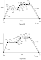
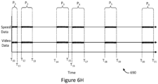
- Figures 6A-6H illustrate another exemplary scenario for data types other than location data (such as speed data or acceleration data).
- Figure 6A is an exemplary plot which illustrates an exemplary set of input telematic data.
- Figures 6A , 6B , 6C , 6D, and 6E are plots which illustrate an exemplary process for generating reduced telematic data from the input telematic data shown in Figure 6A (an example of act 420 and sub-acts 422, 424, and 426 in method 400 of Figure 4 ).
- Figures 6F and 6G are plots which illustrate an exemplary process for interpolating the reduced telematic data (an example of act 408 in method 400).
- Figure 6H is a plot which illustrates interpolated telematic data and video data.
- the input telematic data includes speed data of a vehicle, though the discussion of Figures 6A-6H applies to other types of data as well.
- Figure 6A illustrates speed data collected as a vehicle travels (such as any of vehicles 114 discussed with reference to Figure 1 ).
- a telematic monitoring device (such as telematic monitoring device 104 discussed with reference to Figure 1 ) captures the speed data indicating speed (or velocity) of the vehicle as the vehicle travels.
- each black circle represents a point of speed data included by the telematic monitoring device in the captured input telematic data. Similar to as discussed above regarding location data (and as applicable to any type of telematic data), what is meant by "included by the telematic monitoring device in the captured input telematic data" can have various meanings as appropriate for a given application.
- every point of speed data captured by the telematic monitoring device can be included in the input telematic data.
- captured speed data can be filtered to eliminate outlying data points from the input telematic data. For example, data points which are too far from adjacent data points to be physically possible for the vehicle (e.g. impossible acceleration by the vehicle) can be filtered out, as these data points typically represent sensor errors, communication errors, or other errors. As another example, data points which are outside of reasonable boundaries (e.g. speeds exceeding a top speed of the vehicle) can as be filtered out for similar reasons. As another example, data points which are dissimilar from a pattern of other data points (anomalous data points) can also be filtered out for similar reasons.
- the telematic data being discussed includes speed data, such that a "difference" between a given data point and a reference line represents a difference in speed represented by the data point and represented by the reference line.
- selecting data points from the input telematic data for inclusion in the reduced telematic data, based on differences of the data points to iteratively-defined reference lines defined through portions of the input telematic data includes selecting data points from the input telematic data for inclusion in the reduced telematic data, based on differences in speed between speeds represented by the data points to iteratively-defined reference lines defined through portions of the speed data.
- Figure 6A also illustrates reduction of the set of speed data (the input telematic data in this example).
- a reference line 630 is defined between end points 610 and 612 of the input telematic data.
- reference line 630 is a first reference line of a set of iteratively-defined reference lines as mentioned above regarding acts 420, 422, 424, and 426.
- End points 620 and 612 can be defined in various ways. In some implementations, end points 610 and 612 can be defined as the start and end, respectively, of a trip or journey by the vehicle (e.g. when the vehicle is activated or moved, until the vehicle is deactivated or stops moving).
- end points 610 and 612 can be defined as the start and end, respectively, of a region of data of interest.
- a user can provide input indicating that the data from point 610 to point 612 is of interest, and the generation of reduced telematic data is performed over this region of interest.
- What is considered a region of "interest” is highly application and situation specific, and could for example refer to a region where reduction of telematic data is considered likely to be effective (e.g. journeys over long, straight roads).
- reduced telematic data is generated by selecting data points from the input telematic data, based on differences of the data points to reference lines.
- a minimum difference between respective data points (data points sequentially between end points 610 and 612) and reference line 630 is determined, in accordance with act 422 of method 400.
- a data point of the input telematic data is identified, where a minimum difference between the data point and the reference line 630 is greater than a minimum difference between other data points being compared (sequential points between points 610 and 612) and the reference line 630. That is, a data point of the input telematic data between points 610 and 612 is identified which is the most different from the reference line 630.
- this data point is labelled as point 620, with the minimum difference between point 620 and reference line 630 illustrated by line 631 (perpendicular to reference line 630).
- a specific difference threshold is not illustrated around reference line 630 to reduce clutter, but point 620 lies a great distance from reference line 630 (line 632 is quite long), outside of said difference threshold. Consequently, point 620 is selected for inclusion in the reduced telematic data as in act 426 of method 400.
- the iteratively-defined reference lines are updated to include reference lines which intersect point 620, as is shown in Figure 6B .
- Figure 6B illustrates the set of speed data shown in Figure 6A (the input telematic data in this example).
- a reference line 635 is defined between point 620 and end point 612 of the input telematic data.
- a reference line 640 is defined between end point 610 and point 620 of the input telematic data.
- reference lines 635 and 640 are second and third reference lines of the set of iteratively-defined reference lines as mentioned above regarding acts 420, 422, 424, and 426.
- reduced telematic data is generated by selecting data points from the input telematic data, based on differences of the data points to reference lines.
- a minimum difference between respective data points (data points sequentially between point 620 and 612) and reference line 635 is determined, in accordance with act 422 of method 400.
- a data point of the input telematic data is identified, where a minimum difference between the data point and the reference line 635 is greater than a minimum difference between other data points being compared (sequential data points between points 620 and 612) and the reference line 635. That is, a data point of the input telematic data between points 620 and 612 is identified which is the most different from the reference line 635. In Figure 6B , this data point is labelled as point 621.
- a difference threshold is illustrated around reference line 635, shown as threshold lines 637 and 638.
- point 621 lies within threshold lines 637 and 638, and therefore the minimum difference is within the difference threshold. Consequently, point 621 is not selected for inclusion in the reduced telematic data as in act 426 of method 400.
- point 621 is the most different point from reference line 635 between points 620 and 612, every other point between points 620 and 612 is also within the difference threshold illustrated by threshold lines 637 and 638. Consequently, every point between points 620 and 612 is not selected for inclusion in the reduced telematic data. This is shown in Figure 6B with these points being illustrated in white.
- a minimum difference between respective data points (data points sequentially between end point 610 and point 620) and reference line 640 is determined, in accordance with act 422 of method 400.
- a data point of the input telematic data is identified, where a minimum difference between the data point and the reference line 640 is greater than a minimum difference between other data points being compared (sequential data points between points 610 and 620) and the reference line 640. That is, a data point of the input telematic data between points 610 and 620 is determined which is the most different from the reference line 640. In Figure 6B , this data point is labelled as point 622, and the minimum distance between point 622 and reference line 640 is labelled as line 641.
- a difference threshold is illustrated around reference line 640, shown as threshold lines 642 and 643.
- point 622 lies outside of threshold lines 642 and 643, and therefore the difference is greater than the difference threshold. Consequently, point 622 is selected for inclusion in the reduced telematic data as in act 426 of method 400.
- the iteratively-defined reference lines are updated to include reference lines which intersect point 622, as is shown in Figure 6C .
- Figure 6C illustrates the set of speed data shown in Figure 6A (the input telematic data in this example).
- a reference line 645 is defined between end point 610 and point 622 of the input telematic data.
- a reference line 650 is defined between point 622 and point 620 of the input telematic data.
- reference lines 645 and 650 are fourth and fifth reference lines of the set of iteratively-defined reference lines as mentioned above regarding acts 420, 422, 424, and 426.
- reduced telematic data is generated by selecting data points from the input telematic data, based on differences of the data points to reference lines.
- a minimum difference between respective data points (data points sequentially between point 610 and point 622) and reference line 645 is determined, in accordance with act 422 of method 400.
- a data point of the input telematic data is identified, where a minimum difference between the data point and the reference line 645 is greater than a minimum difference between other data points being compared (sequential points between points 610 and 622) and the reference line 645. That is, a data point of the input telematic data between points 610 and 622 is identified which is the most different from the reference line 645. In Figure 6C , this data point is labelled as point 623.
- a difference threshold is illustrated around reference line 645, shown as threshold lines 647 and 648.
- point 623 lies within threshold lines 647 and 648, and therefore the difference is within the difference threshold. Consequently, point 623 is not selected for inclusion in the reduced telematic data as in act 426 of method 400.
- point 623 is the most different point from reference line 645 between points 610 and 622, every other point between points 610 and 622 is also within the difference threshold illustrated by threshold lines 647 and 648. Consequently, every point between points 610 and 622 is not selected for inclusion in the reduced telematic data. This is shown in Figure 6C with these points being illustrated in white.
- a minimum difference between respective data points (data points sequentially between points 622 and 620) and reference line 650 is determined, in accordance with act 422 of method 400.
- a data point of the input telematic data is identified, where a minimum difference between the data point and the reference line 650 is greater than a minimum difference between other data points being compared (sequential points between points 622 and 620) and the reference line 650. That is, a data point of the input telematic data between points 622 and 620 is identified which is the most different from the reference line 650. In Figure 6C , this data point is labelled as point 624, with a distance from reference line 650 labelled as line 651.
- a difference threshold is illustrated around reference line 650, shown as threshold lines 652 and 653.
- point 624 lies outside of threshold lines 652 and 653, and therefore the difference is greater than the difference threshold. Consequently, point 624 is selected for inclusion in the reduced telematic data as in act 426 of method 400.
- the iteratively-defined reference lines are updated to include reference lines which intersect point 624, as is shown in Figure 6D .
- Figure 6D illustrates the set of speed data shown in Figure 6A (the input telematic data in this example).
- a reference line 655 is defined between point 622 and point 624 of the input telematic data.
- a reference line 660 is defined between point 624 and point 620 of the input telematic data.
- reference lines 655 and 660 are sixth and seventh reference lines of the set of iteratively-defined reference lines as mentioned above regarding acts 420, 422, 424, and 426.
- reduced telematic data is generated by selecting data points from the input telematic data, based on differences of the data points to reference lines.
- a minimum difference between respective data points (data points sequentially between point 622 and point 624) and reference line 655 is determined, in accordance with act 422 of method 400.
- a data point of the input telematic data is identified, where a minimum difference between the data point and the reference line 655 is greater than a minimum difference between other data points being compared (sequential points between points 622 and 624) and the reference line 655. That is, a data point of the input telematic data between points 622 and 624 is identified which is the most different from the reference line 655. In Figure 6D , this data point is labelled as point 625.
- a difference threshold is illustrated around reference line 655, shown as threshold lines 657 and 658.
- point 625 lies within threshold lines 657 and 658, and therefore the difference is within the difference threshold. Consequently, point 625 is not selected for inclusion in the reduced telematic data in act 426 of method 400.
- point 625 is the most different point from reference line 655 between points 622 and 624, every other point between points 622 and 624 is also within the difference threshold illustrated by threshold lines 657 and 658. Consequently, every point between points 622 and 624 is not selected for inclusion in the reduced telematic data. This is shown in Figure 6D with these points being illustrated in white.
- a data point of the input telematic data is identified, where a minimum difference between the data point and the reference line 660 is greater than a minimum difference between other data points being compared (sequential points between points 624 and 620) and the reference line 660. That is, a data point of the input telematic data between points 624 and 620 is identified which is the most different from the reference line 660. In Figure 6D , this data point is labelled as point 626, with a difference between point 626 and reference line 660 labelled as line 662.
- a difference threshold is illustrated around reference line 660, shown as threshold lines 662 and 663.
- point 626 lies outside of threshold lines 662 and 663, and therefore the difference is greater than the difference threshold. Consequently, point 626 is selected for inclusion in the reduced telematic data as in act 426 of method 400.
- the iteratively-defined reference lines are updated to include reference lines which intersect point 626, as is shown in Figure 6E .
- Figure 6E illustrates the set of speed data shown in Figure 6A (the input telematic data in this example).
- a reference line 665 is defined between point 624 and point 626 of the input telematic data.
- a reference line 670 is defined between point 626 and point 620 of the input telematic data.
- reference lines 665 and 670 are eighth and ninth reference lines of the set of iteratively-defined reference lines as mentioned above regarding acts 420, 422, 424, and 426.
- reduced telematic data is generated by selecting data points from the input telematic data, based on differences of the data points to the iteratively-defined reference lines.
- reference line 665 a minimum difference between respective data points (data points sequentially between point 624 and point 626) and reference line 665 is determined, in accordance with act 422 of method 400.
- a data point of the input telematic data is identified, where a minimum difference between the data point and the reference line 665 is greater than a minimum difference between other data points being compared (sequential points between points 624 and 626), and the reference line 665. That is, a data point of the input telematic data between points 624 and 626 is determined which is the most different from the reference line 665. In Figure 6E , this data point is labelled as point 627.
- a difference threshold is illustrated around reference line 665, shown as threshold lines 667 and 668.
- point 627 lies within threshold lines 667 and 668, and therefore the difference is within the difference threshold. Consequently, point 627 is not selected for inclusion in the reduced telematic data in act 426 of method 400.
- point 627 is the most different point from reference line 665 between points 624 and 626, every other point between points 624 and 626 is also within the difference threshold illustrated by threshold lines 624 and 626. Consequently, every point between points 624 and 626 is not selected for inclusion in the reduced telematic data. This is shown in Figure 6E with these points being illustrated in white.
- a data point of the input telematic data is identified, where a minimum difference between the data point and the reference line 670 is greater than a minimum difference between other data points being compared (sequential points between points 626 and 620), and the reference line 670. That is, a data point of the input telematic data between points 626 and 620 is identified which is the most different from the reference line 670. In Figure 6E , this data point is labelled as point 628.
- a difference threshold is illustrated around reference line 670, shown as threshold lines 672 and 673.
- point 628 lies within threshold lines 672 and 673, and therefore the difference is within the difference threshold. Consequently, point 628 is not selected for inclusion in the reduced telematic data in act 426 of method 400.
- point 628 is the most different point from reference line 670 between points 626 and 620, every other point between points 626 and 620 is also within the difference threshold illustrated by threshold lines 672 and 673. Consequently, every point between points 626 and 620 is not selected for inclusion in the reduced telematic data. This is shown in Figure 6E with these points being illustrated in white.
- the input telematic data has been reduced to points which indicate end points of respective reference lines. That is, in Figure 6E , the input telematic data has been reduced from 26 data points to 6 data points. Reference lines 645, 655, 665, 670, and 635 between these 6 data points show a piece-wise speed plot of the vehicle which approximates actual speed during travel of the vehicle (within the above discussed difference thresholds), while requiring significantly less data points to illustrate. In essence, the selected data points 610, 622, 624, 626, 620, and 612 illustrate inflection points, where a speed of the vehicle changes significantly enough to be of note.
- the reduced telematic data is interpolated to generate interpolated telematic data at the synchronized data rate, for a threshold time period around each identified data point in the input telematic data. This is illustrated in Figure 6F , and discussed in detail below.
- Figure 6F illustrates the set of speed data 600 shown in Figure 6A (the input telematic data in this example), reduced to data points 610, 622, 624, 626, 620, and 612 as discussed with reference to Figures 6A-6E .
- Figure 6F illustrates a plurality of times T 10 , T 11 , T 12 , T 13 , T 14 , T 15 , T 16 , T 17 , T 18 , T 19 , T 20 , and T21.
- a time period P 1 is shown between times T 10 and T 11 which corresponds to a threshold time period around identified data point 610.
- the exact duration of time period P 1 can be chosen as appropriate for a given application or implementation (by setting times T 10 and T 11 ), and could for example be ten seconds, 30 seconds, 1 minute, or any other longer or shorter duration of time.
- the reduced telematic data is interpolated around data point 610, within the threshold time period P 1 defined by times T 0 and T 1 . Exemplary means for interpolation are discussed earlier, are applicable here, and are not repeated for brevity.
- interpolated telematic data points can be generated between T 0 and T 1 at the synchronized data rate, along reference line 645 shown in Figure 6E .
- a time period P 2 between times T 12 and T 13 corresponds to a threshold time period around identified data point 622. Similar to as discussed above, the exact duration of this time period can be chosen as appropriate for a given application or implementation (by setting times T 12 and T 13 ).
- the reduced telematic data is interpolated around data point 622, within the threshold time period defined by times T 12 and T 13 . Exemplary means for interpolation are discussed earlier, are applicable here, and are not repeated for brevity.
- interpolated telematic data points can be generated between T 12 and T 13 at the synchronized data rate, along reference lines 645 and 655 shown in Figure 6E .
- a time period P 3 between times T 14 and T 15 corresponds to a threshold time period around identified data point 624. Similar to as discussed above, the exact duration of this time period can be chosen as appropriate for a given application or implementation (by setting times T 14 and T 15 ).
- the reduced telematic data is interpolated around data point 624, within the threshold time period P 3 defined by times T 14 and T 15 . Exemplary means for interpolation are discussed earlier, are applicable here, and are not repeated for brevity. As one example, interpolated telematic data points can be generated between T 14 and T 15 at the synchronized data rate, along reference lines 655 and 665.
- a time period P 4 between times T 16 and T 17 corresponds to a threshold time period around identified data point 626. Similar to as discussed above, the exact duration of this time period P 4 can be chosen as appropriate for a given application or implementation (by setting times T 16 and T 17 ).
- the reduced telematic data is interpolated around data point 626, within the threshold time period defined by times T 16 and T 17 . Exemplary means for interpolation are discussed earlier, are applicable here, and are not repeated for brevity. As one example, interpolated telematic data points can be generated between T 16 and T 17 at the synchronized data rate, along reference lines 665 and 670.
- a time period P 5 between times T 18 and T 19 corresponds to a threshold time period around identified data point 620. Similar to as discussed above, the exact duration of this time period P 5 can be chosen as appropriate for a given application or implementation (by setting times T 18 and T 19 ).
- the reduced telematic data is interpolated around data point 620, within the threshold time period defined by times T 18 and T 19 . Exemplary means for interpolation are discussed earlier, are applicable here, and are not repeated for brevity. As one example, interpolated telematic data points can be generated between T 18 and T 19 at the synchronized data rate, along reference lines 670 and 635.
- a time period P 6 between times T 20 and T 21 corresponds to a threshold time period around identified data point 612. Similar to as discussed above, the exact duration of this time period P 6 can be chosen as appropriate for a given application or implementation (by setting times T 20 and T 21 ).
- the reduced telematic data is interpolated around data point 612, within the threshold time period defined by times T 20 and T 21 . Exemplary means for interpolation are discussed earlier, are applicable here, and are not repeated for brevity. As one example, interpolated telematic data points can be generated between T 20 and T 21 at the synchronized data rate, along reference line 635.
- Figure 6G shows the interpolated telematic data generated in accordance with act 408 of method 400.
- Figure 6G shows data points 610, 622, 624, 626, 620, and 612, as included in the reduced telematic data discussed with reference to Figures 6A-6F .
- Figure 6G also shows a plurality of data points (illustrated as black dots; not individually labelled to reduce clutter) between time T 10 and time T 11 (the threshold time period P 1 around data point 610), which are generated (interpolated) data points, in accordance with act 408 of method 400.
- Figure 6G also shows a plurality of data points (illustrated as black dots; not individually labelled to reduce clutter) between time T 12 and time T 13 (the threshold time period P 2 around data point 622), which are generated (interpolated) data points, in accordance with act 408 of method 400.
- Figure 6G also shows a plurality of data points (illustrated as black dots; not individually labelled to reduce clutter) between time T 14 and time T 15 (the threshold time period P 3 around data point 624), which are generated (interpolated) data points, in accordance with act 408 of method 400.
- Figure 6G also shows a plurality of data points (illustrated as black dots; not individually labelled to reduce clutter) between time T 16 and time T 17 (the threshold time period P 4 around data point 626), which are generated (interpolated) data points, in accordance with act 408 of method 400.
- Figure 6G also shows a plurality of data points (illustrated as black dots; not individually labelled to reduce clutter) between time T 18 and time T 19 (the threshold time period P 5 around data point 620), which are generated (interpolated) data points, in accordance with act 408 of method 400.
- Figure 6G also shows a plurality of data points (illustrated as black dots; not individually labelled to reduce clutter) between time T 20 and time T 21 (the threshold time period P 6 around data point 612), which are generated (interpolated) data points, in accordance with act 408 of method 400.
- Figure 6H shows a plot 690 illustrating interpolated data (telematic data and image data) generated in accordance with acts 206 and 408 of method 400.
- the telematic data includes the interpolated speed data generated in accordance with Figures 6A-6G discussed above.
- the interpolated video data is generated in accordance with act 206 of method 400 by interpolating the input video data in the same threshold time periods shown in Figures 6F and 6G .
- the data points included in the interpolated telematic data and video data are illustrated as black dots, and are not individually labelled to reduce clutter.
- the interpolated video data and interpolated telematic data are at the synchronized data rate, as in method 400.
- the interpolated video data and the interpolated telematic data are sampled at the sample rate in the threshold time period (or threshold time periods).
- the interpolated video data and the interpolated telematic data are sampled in time periods P 1 , P 2 , P 3 , P 4 , P 5 , and P 6 .
- the sampled video data and sampled telematic data are output as synchronized video and telematic data at the sample rate, for each of the above discussed time periods.
- synchronized video and telematic data is generated at the sample rate, around each of data points 610, 622, 624, 626, 620, and 612.
- synchronized video and telematic data is generated around each inflection point in travel of the vehicle. Since each inflection point is more likely to represent a point of interest in the data (compared to other data points where the trajectory of the vehicle is unchanged), this synchronized data represents a meaningful and helpful balance, where quantity of data is generally reduced (by not reporting or keeping data unlikely to be of interest), but data density (frequency of data) is reported or maintained around times where such data is more likely to be of interest.
- interpolation of each of the data sets can be performed for the threshold time period around each identified point from every data set. That is, for an identified data point in one of the data sets, interpolation for a threshold time period around a time of the identified data point is performed for each of the data sets.
- Figures 5A-5G and 6A-6H and the corresponding discussion pertain to telematic data including location data and/or speed data
- the systems and methods herein are applicable to any appropriate telematic data, such as acceleration data, steering wheel input data, pedal input data (brake pedal and/or acceleration pedal), turn signal input data, or any other appropriate type of data.
- a telematic monitoring device captures the acceleration data indicating acceleration of a vehicle as the vehicle travels.
- the discussion of Figures 6A-6H is generally applicable to other data types, including acceleration data, and is not repeated for brevity.
- a "difference" between a given data point and a reference line represents a difference in acceleration of the vehicle represented by the data point and represented by the reference line.
- selecting data points from the input telematic data for inclusion in the reduced telematic data includes selecting data points from the input telematic data for inclusion in the reduced telematic data, based on differences in acceleration of the vehicle between accelerations represented by the data points to iteratively-defined reference lines defined through portions of the acceleration data.
- telematic data can include "motion data" captured by at least one motion sensor.
- motion sensors can include an inertial measurement unit, an accelerometer, or a gyroscope as example.
- Such motion data represents movement of the vehicle (e.g. speed, acceleration, or orientation), or movement of the vehicle can be derived based on motion data.
- a telematic monitoring device captures the driver input data indicating state of the driver input mechanism (e.g. pedal position, turn signal lever position).
- state of the driver input mechanism e.g. pedal position, turn signal lever position.
- a "difference" between a given data point and a reference line represents a difference in state of the input mechanism as represented by the data point and as represented by the reference line.
- selecting data points from the input telematic data for inclusion in the reduced telematic data includes selecting data points from the input telematic data for inclusion in the reduced telematic data, based on differences in state of an input mechanism as represented by the data points to iteratively-defined reference lines defined through portions of the driver input data.
- audio data may also be captured.
- a telematic monitoring device such as telematic monitoring device 104 discussed with reference to Figure 1
- an audio sensor e.g. microphone
- an image sensor such as image sensors 134 discussed with reference to Figure 1
- an audio sensor e.g. microphone
- a separate audio sensor e.g. microphone
- input audio data can be accessed (similar to as in acts 202 of methods 200 and 400), interpolated to a synchronized data rate (similar to as in acts 206, 208, and 408 of methods 200 and 400), and sampled at a sampled data rate (similar to as in acts 210 and 410 of methods 200 and 400), to synchronize the audio data to other types of data.
- audio data is commonly captured at a high data rate (e.g. above 1 kHz).
- the high data rate of audio data may already be significantly higher than data rates of other captured forms of data.
- the audio data rate can be set as the synchronized data rate, and the other types of data (video data and/or telematic data) can be interpolated up to match the audio data rate.
- synchronized video and telematics data (as generated in method 200 in Figure 2 and method 400 in Figure 4 ) can be used to populate a roadway signage or rules database.
- location data for a vehicle may not accurately reflect positioning of a sign or signal for a roadway.
- a vehicle may pass a stop sign at a certain time. If vehicle position data is collected and/or reported sporadically or sparsely, video data which includes a representation of the stop sign may not be temporally close to location data for the vehicle. As a result, an actual location of the stop sign may not be accurately reported or determinable.
- position of the vehicle and video data which represents a sign from a perspective of the vehicle can be temporally aligned, such that position of the sign can be determined based on position of the vehicle.
- a sign which appears on a right-most edge of video data captured by a vehicle may be determined as being at a position a certain number of meters ahead of and to the right (from the perspective of the vehicle) of the vehicle position.
- a sign could be determined as being 3 meters in front of the vehicle and 2 meters to the right of the vehicle.
- the exact amount of meters can vary based on vehicle shape or height, and/or position and orientation of an image capture device at the vehicle. Consequently, generating synchronized video and telematics data can result in improved accuracy in generation of roadway signage and rules databases.
- telematics data can include inertial data, such as accelerometer data and/or gyroscope data.
- inertial data such as accelerometer data and/or gyroscope data.
- unsynchronized data when used to train a machine learning model, can result in a model which is not accurately trained.
- synchronized data can be made available for use in training or detection by one or more machine learning models.
- audio data can be grouped (conceptually or technically) together with the input telematic data, and can be interpolated together therewith (i.e. in acts 208 or 408).
- infinitive verb forms are often used, such as “to operate” or “to couple”. Unless context dictates otherwise, such infinitive verb forms are used in an open and inclusive manner, such as “to at least operate” or “to at least couple”.
- ASICs application-specific integrated circuits
- ICs standard integrated circuits
- PLDs programmable logic devices
- FPGAs field-programmable gate arrays
- the disclosure includes descriptions of several processors.
- Said processors can be implemented as any hardware capable of processing data, such as application-specific integrated circuits (ASICs), standard integrated circuits (ICs), programmable logic devices (PLDs), field-programmable gate arrays (FPGAs), logic circuits, or any other appropriate hardware.
- ASICs application-specific integrated circuits
- ICs integrated circuits
- PLDs programmable logic devices
- FPGAs field-programmable gate arrays
- the disclosure also includes descriptions of several non-transitory processor-readable storage mediums.
- Said non-transitory processor-readable storage mediums can be implemented as any hardware capable of storing data, such as magnetic drives, flash drives, RAM, or any other appropriate data storage hardware.
- mention of data or information being stored at a device e.g. vehicle device 122 or network device 110
- a non-transitory processor-readable storage medium of said device e.g. non-transitory processor-readable storage mediums 116 or 126.
Landscapes
- Engineering & Computer Science (AREA)
- Multimedia (AREA)
- Signal Processing (AREA)
- Chemical & Material Sciences (AREA)
- Analytical Chemistry (AREA)
- Physics & Mathematics (AREA)
- General Physics & Mathematics (AREA)
- Traffic Control Systems (AREA)
Priority Applications (1)
| Application Number | Priority Date | Filing Date | Title |
|---|---|---|---|
| EP26155404.2A EP4727017A2 (de) | 2023-02-09 | 2024-01-11 | Systeme, vorrichtungen und verfahren zur synchronisierung von daten aus asynchronen quellen |
Applications Claiming Priority (1)
| Application Number | Priority Date | Filing Date | Title |
|---|---|---|---|
| US202363444434P | 2023-02-09 | 2023-02-09 |
Related Child Applications (1)
| Application Number | Title | Priority Date | Filing Date |
|---|---|---|---|
| EP26155404.2A Division EP4727017A2 (de) | 2023-02-09 | 2024-01-11 | Systeme, vorrichtungen und verfahren zur synchronisierung von daten aus asynchronen quellen |
Publications (1)
| Publication Number | Publication Date |
|---|---|
| EP4414961A1 true EP4414961A1 (de) | 2024-08-14 |
Family
ID=89619027
Family Applications (2)
| Application Number | Title | Priority Date | Filing Date |
|---|---|---|---|
| EP24151341.5A Pending EP4414961A1 (de) | 2023-02-09 | 2024-01-11 | Systeme, vorrichtungen und verfahren zur synchronisierung von daten aus asynchronen quellen |
| EP26155404.2A Pending EP4727017A2 (de) | 2023-02-09 | 2024-01-11 | Systeme, vorrichtungen und verfahren zur synchronisierung von daten aus asynchronen quellen |
Family Applications After (1)
| Application Number | Title | Priority Date | Filing Date |
|---|---|---|---|
| EP26155404.2A Pending EP4727017A2 (de) | 2023-02-09 | 2024-01-11 | Systeme, vorrichtungen und verfahren zur synchronisierung von daten aus asynchronen quellen |
Country Status (2)
| Country | Link |
|---|---|
| US (1) | US12284461B2 (de) |
| EP (2) | EP4414961A1 (de) |
Families Citing this family (1)
| Publication number | Priority date | Publication date | Assignee | Title |
|---|---|---|---|---|
| CN120763132B (zh) * | 2025-04-18 | 2026-04-14 | 清华大学 | 多源数据集成系统 |
Citations (3)
| Publication number | Priority date | Publication date | Assignee | Title |
|---|---|---|---|---|
| US20200284883A1 (en) * | 2019-03-08 | 2020-09-10 | Osram Gmbh | Component for a lidar sensor system, lidar sensor system, lidar sensor device, method for a lidar sensor system and method for a lidar sensor device |
| US11022444B1 (en) | 2020-06-16 | 2021-06-01 | Geotab Inc. | Dataset simplification of multidimensional signals captured for asset tracking |
| US20220343531A1 (en) * | 2021-04-27 | 2022-10-27 | Here Global B.V. | Systems and methods for synchronizing an image sensor |
Family Cites Families (66)
| Publication number | Priority date | Publication date | Assignee | Title |
|---|---|---|---|---|
| IL161002A0 (en) | 2004-03-22 | 2004-08-31 | Itay Katz | Virtual video keyboard system |
| US8849501B2 (en) | 2009-01-26 | 2014-09-30 | Lytx, Inc. | Driver risk assessment system and method employing selectively automatic event scoring |
| EP2578996B1 (de) | 2008-02-15 | 2018-10-17 | Continental Teves AG & Co. OHG | Fahrzeugsystem zur Navigation und/oder Fahrerassistenz |
| CN102356398B (zh) | 2009-02-02 | 2016-11-23 | 视力移动技术有限公司 | 用于视频流中的对象识别和跟踪的系统和方法 |
| GB2476298A (en) * | 2009-12-18 | 2011-06-22 | Snell Ltd | Changing the temporal sample rate of a motion image sequence |
| CN102455945A (zh) | 2010-10-27 | 2012-05-16 | 鸿富锦精密工业(深圳)有限公司 | 基板管理控制器恢复系统及其使用方法 |
| US9298575B2 (en) | 2011-10-12 | 2016-03-29 | Lytx, Inc. | Drive event capturing based on geolocation |
| US8791806B2 (en) | 2011-11-28 | 2014-07-29 | Trimble Navigation Limited | Real-time detection of hazardous driving |
| US8676428B2 (en) | 2012-04-17 | 2014-03-18 | Lytx, Inc. | Server request for downloaded information from a vehicle-based monitor |
| US9240079B2 (en) | 2012-04-17 | 2016-01-19 | Lytx, Inc. | Triggering a specialized data collection mode |
| US9344683B1 (en) | 2012-11-28 | 2016-05-17 | Lytx, Inc. | Capturing driving risk based on vehicle state and automatic detection of a state of a location |
| US9389147B1 (en) | 2013-01-08 | 2016-07-12 | Lytx, Inc. | Device determined bandwidth saving in transmission of events |
| US9761063B2 (en) | 2013-01-08 | 2017-09-12 | Lytx, Inc. | Server determined bandwidth saving in transmission of events |
| US8952819B2 (en) | 2013-01-31 | 2015-02-10 | Lytx, Inc. | Direct observation event triggering of drowsiness |
| US8930072B1 (en) | 2013-07-26 | 2015-01-06 | Lytx, Inc. | Managing the camera acquiring interior data |
| US9098956B2 (en) | 2013-09-26 | 2015-08-04 | Lytx, Inc. | Dynamic uploading protocol |
| CN110120072B (zh) | 2013-12-19 | 2023-05-09 | 苹果公司 | 用于跟踪移动设备的方法和系统 |
| US9646651B1 (en) | 2014-07-11 | 2017-05-09 | Lytx, Inc. | Marking stored video |
| US10686976B2 (en) | 2014-08-18 | 2020-06-16 | Trimble Inc. | System and method for modifying onboard event detection and/or image capture strategy using external source data |
| US10204159B2 (en) | 2015-08-21 | 2019-02-12 | Trimble Navigation Limited | On-demand system and method for retrieving video from a commercial vehicle |
| US9996756B2 (en) | 2015-08-31 | 2018-06-12 | Lytx, Inc. | Detecting risky driving with machine vision |
| US10152870B1 (en) | 2016-02-22 | 2018-12-11 | Lytx, Inc. | Compliance detection |
| WO2018218146A1 (en) | 2017-05-26 | 2018-11-29 | Google Llc | Data layers for a vehicle map service |
| US10496891B2 (en) | 2017-08-17 | 2019-12-03 | Harman International Industries, Incorporated | Driver assistance system and method for object detection and notification |
| US10785524B1 (en) | 2017-11-07 | 2020-09-22 | Lytx, Inc. | Telematics integration enabling indexing and viewing of associated event videos |
| DE102017221765A1 (de) | 2017-12-04 | 2019-06-06 | Robert Bosch Gmbh | Trainieren und Betreiben eines Maschinen-Lern-Systems |
| US11994405B2 (en) | 2018-03-07 | 2024-05-28 | Google Llc | Methods and systems for determining geographic orientation based on imagery |
| US10885360B1 (en) | 2018-06-15 | 2021-01-05 | Lytx, Inc. | Classification using multiframe analysis |
| JP2021530069A (ja) | 2018-06-26 | 2021-11-04 | カッツ,イテイ | 状況的ドライバ監視システム |
| DE102018211042A1 (de) | 2018-07-04 | 2020-01-09 | Robert Bosch Gmbh | Schnelle Erkennung gefährlicher oder gefährdeter Objekte im Umfeld eines Fahrzeugs |
| WO2020068835A1 (en) | 2018-09-24 | 2020-04-02 | Intel Corporation | Negotiation of a pc5 rat for a v2x service |
| WO2020069088A2 (en) | 2018-09-28 | 2020-04-02 | Intel Corporation | Improved groupcast and unicast in new radio vehicle-to-everything (v2x) communication |
| WO2020092706A1 (en) | 2018-11-01 | 2020-05-07 | Intel Corporation | Qos-aware congestion control, resource allocation and in-device coexistence solutions for nr v2x sidelink communication |
| WO2020092931A1 (en) | 2018-11-02 | 2020-05-07 | Intel Corporation | Resource allocation and processing behaviors for nr v2x sidelink communications |
| DE102018219976A1 (de) | 2018-11-22 | 2020-05-28 | Robert Bosch Gmbh | Vorrichtung und Verfahren zur Warnung eines Fahrers eines Fahrzeugs |
| WO2020146893A1 (en) | 2019-01-11 | 2020-07-16 | Apple Inc. | Sidelink physical layer procedures for collision avoidance, harq feedback, and csi acquisition |
| DE102020201827A1 (de) | 2019-02-13 | 2020-08-20 | Apple Inc. | V2x-netzwerkunterstützte side-link-konfiguration und datenübertragung |
| US10999374B2 (en) | 2019-04-26 | 2021-05-04 | Samsara Inc. | Event detection system |
| US11080568B2 (en) | 2019-04-26 | 2021-08-03 | Samsara Inc. | Object-model based event detection system |
| US12056922B2 (en) | 2019-04-26 | 2024-08-06 | Samsara Inc. | Event notification system |
| US11787413B2 (en) | 2019-04-26 | 2023-10-17 | Samsara Inc. | Baseline event detection system |
| US11494921B2 (en) | 2019-04-26 | 2022-11-08 | Samsara Networks Inc. | Machine-learned model based event detection |
| US20210229673A1 (en) | 2019-06-17 | 2021-07-29 | Google Llc | Seamless driver authentication using an in-vehicle camera in conjunction with a trusted mobile computing device |
| US11010640B1 (en) | 2019-06-24 | 2021-05-18 | Lytx, Inc. | Automated training data quality process |
| US11915115B2 (en) | 2019-12-31 | 2024-02-27 | Google Llc | Lane selection using machine learning |
| KR20220123688A (ko) | 2020-02-13 | 2022-09-08 | 애플 인크. | 효율적인 차량 대 사물(v2x) pc5 킵 얼라이브 |
| US11140236B2 (en) | 2020-02-20 | 2021-10-05 | Samsara Networks Inc. | Device arrangement for deriving a communication data scheme |
| KR102778774B1 (ko) | 2020-04-01 | 2025-03-12 | 애플 인크. | 피어 사용자 장비(ue)들 사이의 차량 대 사물(v2x) 보안 정책 협상 |
| DE102020208008A1 (de) | 2020-06-29 | 2021-12-30 | Robert Bosch Gesellschaft mit beschränkter Haftung | Bildklassifikation und zugehöriges Training für sicherheitsrelevante Klassifikationsaufgaben |
| DE102020208080A1 (de) | 2020-06-30 | 2021-12-30 | Robert Bosch Gesellschaft mit beschränkter Haftung | Erkennung von Objekten in Bildern unter Äquivarianz oder Invarianz gegenüber der Objektgröße |
| US11310069B2 (en) | 2020-07-30 | 2022-04-19 | Samsara Networks Inc. | Variable termination in a vehicle communication bus |
| US12232113B2 (en) | 2020-08-06 | 2025-02-18 | Apple Inc. | Reduced sensing schemes for sidelink enhancement |
| US11452062B1 (en) | 2020-09-11 | 2022-09-20 | Lytx, Inc. | Edge model detection and management for distributed data collection |
| US11341786B1 (en) | 2020-11-13 | 2022-05-24 | Samsara Inc. | Dynamic delivery of vehicle event data |
| US11888716B1 (en) | 2021-01-22 | 2024-01-30 | Samsara Inc. | Dynamic scheduling of data transmission from internet of things (IoT) devices based on density of IoT devices |
| US11157723B1 (en) | 2021-02-12 | 2021-10-26 | Samsara Networks lac. | Facial recognition for drivers |
| US11356605B1 (en) | 2021-05-10 | 2022-06-07 | Samsara Inc. | Dual-stream video management |
| US20220402521A1 (en) | 2021-06-16 | 2022-12-22 | Waymo Llc | Autonomous path generation with path optimization |
| US12333817B2 (en) | 2021-08-03 | 2025-06-17 | Waymo Llc | Association of camera images and radar data in autonomous vehicle applications |
| US11863712B1 (en) | 2021-10-06 | 2024-01-02 | Samsara Inc. | Daisy chaining dash cams |
| US11352014B1 (en) | 2021-11-12 | 2022-06-07 | Samsara Inc. | Tuning layers of a modular neural network |
| US11917040B1 (en) | 2022-03-30 | 2024-02-27 | Amazon Technologies, Inc. | Converting communication protocols for messages to enable internet access for vehicle applications |
| US11683579B1 (en) | 2022-04-04 | 2023-06-20 | Samsara Inc. | Multistream camera architecture |
| US12300041B2 (en) | 2022-06-10 | 2025-05-13 | Amazon Technologies, Inc. | Vehicle data stream subscription system |
| US12487128B2 (en) | 2022-07-01 | 2025-12-02 | Samsara Inc. | Electronic device for monitoring vehicle environments |
| US11930082B1 (en) | 2022-12-15 | 2024-03-12 | Amazon Technologies, Inc. | Multiple zone communications and controls |
-
2024
- 2024-01-11 EP EP24151341.5A patent/EP4414961A1/de active Pending
- 2024-01-11 EP EP26155404.2A patent/EP4727017A2/de active Pending
- 2024-01-24 US US18/420,976 patent/US12284461B2/en active Active
Patent Citations (4)
| Publication number | Priority date | Publication date | Assignee | Title |
|---|---|---|---|---|
| US20200284883A1 (en) * | 2019-03-08 | 2020-09-10 | Osram Gmbh | Component for a lidar sensor system, lidar sensor system, lidar sensor device, method for a lidar sensor system and method for a lidar sensor device |
| US11022444B1 (en) | 2020-06-16 | 2021-06-01 | Geotab Inc. | Dataset simplification of multidimensional signals captured for asset tracking |
| EP3926602A1 (de) * | 2020-06-16 | 2021-12-22 | GEOTAB Inc. | Datensatzvereinfachung von mehrdimensionalen signalen, die für die verfolgung von vermögenswerten efasst werden |
| US20220343531A1 (en) * | 2021-04-27 | 2022-10-27 | Here Global B.V. | Systems and methods for synchronizing an image sensor |
Non-Patent Citations (2)
| Title |
|---|
| DU YUCHUAN ET AL: "A Novel Spatio-Temporal Synchronization Method of Roadside Asynchronous MMW Radar-Camera for Sensor Fusion", IEEE TRANSACTIONS ON INTELLIGENT TRANSPORTATION SYSTEMS, IEEE, PISCATAWAY, NJ, USA, vol. 23, no. 11, 1 November 2022 (2022-11-01), pages 22278 - 22289, XP011926403, ISSN: 1524-9050, [retrieved on 20211027], DOI: 10.1109/TITS.2021.3119079 * |
| LIU CHAO ET AL: "An Asynchronous Trajectory Matching Method Based on Piecewise Space-Time Constraints", IEEE ACCESS, IEEE, USA, vol. 8, 11 December 2020 (2020-12-11), pages 224712 - 224728, XP011827846, DOI: 10.1109/ACCESS.2020.3044102 * |
Also Published As
| Publication number | Publication date |
|---|---|
| US12284461B2 (en) | 2025-04-22 |
| EP4727017A2 (de) | 2026-04-15 |
| US20240275917A1 (en) | 2024-08-15 |
Similar Documents
| Publication | Publication Date | Title |
|---|---|---|
| JP7291201B2 (ja) | 車両衝突の車両テレマティクス | |
| US9996756B2 (en) | Detecting risky driving with machine vision | |
| EP3374981B1 (de) | Verkehrskalkulation | |
| EP2943884B1 (de) | Servergesteuerte bandbreitenersparnis bei der übertragung von ereignissen | |
| US9685098B1 (en) | Driver compliance risk adjustments | |
| US12049218B2 (en) | Evaluating the safety performance of vehicles | |
| CN107767661B (zh) | 车辆实时跟踪系统 | |
| US11823564B1 (en) | Adaptive data collection based on fleet-wide intelligence | |
| US11202030B2 (en) | System and method for providing complete event data from cross-referenced data memories | |
| CN110995771A (zh) | 一种基于物联网的货车陆运监控管理系统 | |
| EP4060628B1 (de) | Systeme und verfahren zur fahrzeugdatenerfassung durch bildanalyse | |
| EP4414961A1 (de) | Systeme, vorrichtungen und verfahren zur synchronisierung von daten aus asynchronen quellen | |
| CN113924605B (zh) | 检测用于检查图像分析系统的图像材料的方法、在该方法中使用的装置和交通工具以及计算机可读的存储介质 | |
| US11615654B1 (en) | Signature use for efficient data transfer | |
| CN104908694A (zh) | 用于行驶轨迹鉴定的系统及其数据采集装置 | |
| US12337841B2 (en) | Systems and methods for vehicle reversing detection using edge machine learning | |
| CN118334853A (zh) | 道路上交通对象的车道分配 | |
| US12517951B1 (en) | Systems and methods for communicating vehicle-related image data | |
| EP4546289A1 (de) | Systeme zur erkennung von rollanschlägen | |
| EP4210018B1 (de) | Systeme und verfahren zur fahrzeugumkehrerkennung unter verwendung von maschinellem kantenlernen | |
| US12596196B2 (en) | Systems and methods for calibrating vehicle following distance determination | |
| US12568348B2 (en) | Systems, devices, and methods for communicating vehicle-related image data | |
| US12198475B1 (en) | Orchestrated intelligent edge sensing | |
| JP2018181186A (ja) | 燃費計測装置、燃費計測システム及び燃費計測方法 | |
| WO2022116804A1 (en) | Probe car data transmission reduction |
Legal Events
| Date | Code | Title | Description |
|---|---|---|---|
| PUAI | Public reference made under article 153(3) epc to a published international application that has entered the european phase |
Free format text: ORIGINAL CODE: 0009012 |
|
| STAA | Information on the status of an ep patent application or granted ep patent |
Free format text: STATUS: THE APPLICATION HAS BEEN PUBLISHED |
|
| AK | Designated contracting states |
Kind code of ref document: A1 Designated state(s): AL AT BE BG CH CY CZ DE DK EE ES FI FR GB GR HR HU IE IS IT LI LT LU LV MC ME MK MT NL NO PL PT RO RS SE SI SK SM TR |
|
| STAA | Information on the status of an ep patent application or granted ep patent |
Free format text: STATUS: REQUEST FOR EXAMINATION WAS MADE |
|
| 17P | Request for examination filed |
Effective date: 20250204 |
|
| GRAP | Despatch of communication of intention to grant a patent |
Free format text: ORIGINAL CODE: EPIDOSNIGR1 |
|
| STAA | Information on the status of an ep patent application or granted ep patent |
Free format text: STATUS: GRANT OF PATENT IS INTENDED |
|
| INTG | Intention to grant announced |
Effective date: 20250924 |
|
| GRAJ | Information related to disapproval of communication of intention to grant by the applicant or resumption of examination proceedings by the epo deleted |
Free format text: ORIGINAL CODE: EPIDOSDIGR1 |
|
| STAA | Information on the status of an ep patent application or granted ep patent |
Free format text: STATUS: REQUEST FOR EXAMINATION WAS MADE |
|
| GRAP | Despatch of communication of intention to grant a patent |
Free format text: ORIGINAL CODE: EPIDOSNIGR1 |
|
| STAA | Information on the status of an ep patent application or granted ep patent |
Free format text: STATUS: GRANT OF PATENT IS INTENDED |
|
| GRAJ | Information related to disapproval of communication of intention to grant by the applicant or resumption of examination proceedings by the epo deleted |
Free format text: ORIGINAL CODE: EPIDOSDIGR1 |
|
| STAA | Information on the status of an ep patent application or granted ep patent |
Free format text: STATUS: REQUEST FOR EXAMINATION WAS MADE |
|
| INTC | Intention to grant announced (deleted) | ||
| INTG | Intention to grant announced |
Effective date: 20260202 |
|
| GRAP | Despatch of communication of intention to grant a patent |
Free format text: ORIGINAL CODE: EPIDOSNIGR1 |
|
| STAA | Information on the status of an ep patent application or granted ep patent |
Free format text: STATUS: GRANT OF PATENT IS INTENDED |
|
| INTC | Intention to grant announced (deleted) | ||
| INTG | Intention to grant announced |
Effective date: 20260312 |
|
| GRAS | Grant fee paid |
Free format text: ORIGINAL CODE: EPIDOSNIGR3 |
|
| GRAA | (expected) grant |
Free format text: ORIGINAL CODE: 0009210 |
|
| STAA | Information on the status of an ep patent application or granted ep patent |
Free format text: STATUS: THE PATENT HAS BEEN GRANTED |