EP4414969A1 - Ensemble endoscope, ensemble caméra endoscopique et dispositif d'endoscopie - Google Patents
Ensemble endoscope, ensemble caméra endoscopique et dispositif d'endoscopie Download PDFInfo
- Publication number
- EP4414969A1 EP4414969A1 EP23461515.1A EP23461515A EP4414969A1 EP 4414969 A1 EP4414969 A1 EP 4414969A1 EP 23461515 A EP23461515 A EP 23461515A EP 4414969 A1 EP4414969 A1 EP 4414969A1
- Authority
- EP
- European Patent Office
- Prior art keywords
- endoscope
- assembly
- camera
- housing
- assembly according
- Prior art date
- Legal status (The legal status is an assumption and is not a legal conclusion. Google has not performed a legal analysis and makes no representation as to the accuracy of the status listed.)
- Pending
Links
Images

Classifications
-
- A—HUMAN NECESSITIES
- A61—MEDICAL OR VETERINARY SCIENCE; HYGIENE
- A61B—DIAGNOSIS; SURGERY; IDENTIFICATION
- A61B1/00—Instruments for performing medical examinations of the interior of cavities or tubes of the body by visual or photographical inspection, e.g. endoscopes; Illuminating arrangements therefor
- A61B1/00163—Optical arrangements
- A61B1/00174—Optical arrangements characterised by the viewing angles
- A61B1/00183—Optical arrangements characterised by the viewing angles for variable viewing angles
-
- G—PHYSICS
- G09—EDUCATION; CRYPTOGRAPHY; DISPLAY; ADVERTISING; SEALS
- G09B—EDUCATIONAL OR DEMONSTRATION APPLIANCES; APPLIANCES FOR TEACHING, OR COMMUNICATING WITH, THE BLIND, DEAF OR MUTE; MODELS; PLANETARIA; GLOBES; MAPS; DIAGRAMS
- G09B23/00—Models for scientific, medical, or mathematical purposes, e.g. full-sized devices for demonstration purposes
- G09B23/28—Models for scientific, medical, or mathematical purposes, e.g. full-sized devices for demonstration purposes for medicine
- G09B23/285—Models for scientific, medical, or mathematical purposes, e.g. full-sized devices for demonstration purposes for medicine for injections, endoscopy, bronchoscopy, sigmoidscopy, insertion of contraceptive devices or enemas
-
- A—HUMAN NECESSITIES
- A61—MEDICAL OR VETERINARY SCIENCE; HYGIENE
- A61B—DIAGNOSIS; SURGERY; IDENTIFICATION
- A61B1/00—Instruments for performing medical examinations of the interior of cavities or tubes of the body by visual or photographical inspection, e.g. endoscopes; Illuminating arrangements therefor
- A61B1/00002—Operational features of endoscopes
- A61B1/00057—Operational features of endoscopes provided with means for testing or calibration
-
- A—HUMAN NECESSITIES
- A61—MEDICAL OR VETERINARY SCIENCE; HYGIENE
- A61B—DIAGNOSIS; SURGERY; IDENTIFICATION
- A61B1/00—Instruments for performing medical examinations of the interior of cavities or tubes of the body by visual or photographical inspection, e.g. endoscopes; Illuminating arrangements therefor
- A61B1/00064—Constructional details of the endoscope body
- A61B1/00071—Insertion part of the endoscope body
- A61B1/0008—Insertion part of the endoscope body characterised by distal tip features
- A61B1/00096—Optical elements
-
- A—HUMAN NECESSITIES
- A61—MEDICAL OR VETERINARY SCIENCE; HYGIENE
- A61B—DIAGNOSIS; SURGERY; IDENTIFICATION
- A61B1/00—Instruments for performing medical examinations of the interior of cavities or tubes of the body by visual or photographical inspection, e.g. endoscopes; Illuminating arrangements therefor
- A61B1/00112—Connection or coupling means
- A61B1/00121—Connectors, fasteners and adapters, e.g. on the endoscope handle
- A61B1/00126—Connectors, fasteners and adapters, e.g. on the endoscope handle optical, e.g. for light supply cables
-
- A—HUMAN NECESSITIES
- A61—MEDICAL OR VETERINARY SCIENCE; HYGIENE
- A61B—DIAGNOSIS; SURGERY; IDENTIFICATION
- A61B1/00—Instruments for performing medical examinations of the interior of cavities or tubes of the body by visual or photographical inspection, e.g. endoscopes; Illuminating arrangements therefor
- A61B1/04—Instruments for performing medical examinations of the interior of cavities or tubes of the body by visual or photographical inspection, e.g. endoscopes; Illuminating arrangements therefor combined with photographic or television appliances
- A61B1/042—Instruments for performing medical examinations of the interior of cavities or tubes of the body by visual or photographical inspection, e.g. endoscopes; Illuminating arrangements therefor combined with photographic or television appliances characterised by a proximal camera, e.g. a CCD camera
-
- H—ELECTRICITY
- H04—ELECTRIC COMMUNICATION TECHNIQUE
- H04N—PICTORIAL COMMUNICATION, e.g. TELEVISION
- H04N23/00—Cameras or camera modules comprising electronic image sensors; Control thereof
- H04N23/50—Constructional details
-
- H—ELECTRICITY
- H04—ELECTRIC COMMUNICATION TECHNIQUE
- H04N—PICTORIAL COMMUNICATION, e.g. TELEVISION
- H04N23/00—Cameras or camera modules comprising electronic image sensors; Control thereof
- H04N23/50—Constructional details
- H04N23/51—Housings
-
- H—ELECTRICITY
- H04—ELECTRIC COMMUNICATION TECHNIQUE
- H04N—PICTORIAL COMMUNICATION, e.g. TELEVISION
- H04N23/00—Cameras or camera modules comprising electronic image sensors; Control thereof
- H04N23/50—Constructional details
- H04N23/555—Constructional details for picking-up images in sites, inaccessible due to their dimensions or hazardous conditions, e.g. endoscopes or borescopes
-
- H—ELECTRICITY
- H04—ELECTRIC COMMUNICATION TECHNIQUE
- H04N—PICTORIAL COMMUNICATION, e.g. TELEVISION
- H04N23/00—Cameras or camera modules comprising electronic image sensors; Control thereof
- H04N23/60—Control of cameras or camera modules
Definitions
- the subject invention pertains to the field of training simulators intended for training endoscope operating skills. Training may be carried out with the use of training inserts or with the use of virtual reality technology.
- a standard endoscopy set comprises a camera, an optical adapter and an endoscope.
- the camera is connected to the optical adapter and the endoscope may rotate about the adapter.
- the endoscope may rotate about the adapter.
- their rotation about their own axis relative to the camera causes that the surgeon may inspect visually hardly accessible sites during the surgical procedure, while maintaining orientation and coordination with the camera image.
- Skills in proper operation of such angular endoscope are critical in particular at the initial stage of training of endoscopy surgery. Additionally, the operator of the camera should take care to ensure always sharp image from the camera.
- a training system for training skills in operating an endoscopy camera may be executed in virtual reality.
- the image captured by the camera is then computer-simulated.
- Training may be also carried out with the use of training inserts comprising respective exercises. In both cases it is required to measure key parameters for the endoscopy camera - the rotation angle of the endoscope relative to the camera and the angle of the image sharpness adjustment knob.
- Application EP1504431A1 teaches a laparoscope simulator, comprising an apparatus in a shape of a human body through which the laparoscopy instrument is inserted. Cameras capture video image and a graphics engine uses 3D data to generate representation of the internal scenes. The simulator uses a motion analysis engine for monitoring the instrument to determine the extent of rotation about the axis. The instrument additionally has conical markings that enable monitoring the rotation and the depth at which the instrument is inserted.
- Application US20220139260A1 teaches a simulator and a simulation system in virtual and augmented reality, in particular for endoscopy simulators. Additionally, the system comprises a sensor in the rotary element or uses two cameras for detection of orientation of the anatomic model.
- Application US20190355278A1 teaches s surgical system in virtual reality, with a haptic feedback coupling.
- the system comprises a tool rotation sensor assembly comprising a code wheel with lines arranged thereon and PCBs configured to measure rotations of the code wheel based on the measured lines.
- the subject-matter of the invention provides an endoscope assembly comprising an endoscope comprising preferably a fiber optic connection and an endoscope housing.
- the endoscope assembly is characterized in that it further comprises an endoscope rotation measurement assembly which is arranged within the housing of the endoscope.
- On the endoscope a toothed wheel is mounted fixedly, said toothed wheel being configured to cooperate with a movable toothed wheel.
- the movable toothed wheel is seated at the first end of a shaft, the shaft being seated in the housing rotatably. Preferably, it is seated via a bearing.
- the measurement assembly of the endoscope comprises a rotation sensor configured to measure shaft rotation, and furthermore the endoscope rotation measurement assembly comprises an endoscope interface, preferably in a form of an endoscope connector configured to transfer data from the rotation sensor.
- the endoscope housing comprises a protrusion.
- the toothed wheel and the movable toothed wheel are oblique wheels, and more preferably the axis of the toothed wheel and the axis of the movable toothed wheel define the right angle.
- the rotation sensor comprises an encoder and a magnet arranged on the other end of the shaft.
- it comprises an endoscope printed circuit which comprises an encoder and an endoscope interface.
- the play elimination mechanism comprises a spring, more preferably a spiral spring capable to apply torque to the shaft and the housing, and even more preferably between the spring and the shaft there is arranged a mounting pin to which the spring is mounted.
- the central axis of the field of view of the endoscope is parallel or angled relative to the endoscope axis.
- the endoscope housing comprises a rotation limiting mechanism to prevent the endoscope from rotating a full turn about its own axis relative to the housing, more preferably in a form of an arm mounted perpendicularly to the endoscope axis and an element parallel to the endoscope and protruding above the arm, and more preferably the arm is a fiber optic connection.
- Another object of the invention is an endoscopic camera assembly comprising a camera housing comprising a sensor case of a vision sensor, the vision sensor being positioned preferably on the sensor printed circuit of the vision sensor; a camera interface configured to transfer data from the endoscopic camera assembly, preferably in a form of a camera connector.
- the endoscopic camera assembly is characterized in that the optical adapter is configured to be connected to the endoscope assembly and to prevent the endoscope assembly from rotating relative to the endoscope axis, preferably by means of a shaped connection with a protrusion of the endoscope assembly so that the image from the endoscope is captured by the vision sensor.
- On the optical adapter an adapter case is fixedly applied.
- the optical adapter comprises a sharpness adjustment knob.
- the endoscopic camera assembly comprises an assembly for measuring position of the sharpness adjustment knob.
- the endoscopic camera assembly preferably comprises an accelerometer.
- the assembly for measuring position of the sharpness adjustment knob comprises a reflector and a knob position sensor configured to read out the reflector position.
- the knob position sensor is arranged in the adapter case, and more preferably the knob position sensor and/or accelerometer are seated on the optical adapter printed circuit.
- the adapter interface capable to receive data from the endoscope interface and to transfer the received data to the camera interface, preferably the adapter interface being positioned on the optical adapter printed circuit.
- the reflector is positioned on the sidewall of the sharpness adjustment knob.
- the reflector is a sticker with variable optical parameters or a furrow with variable depth along a section of a circle.
- the camera housing comprises camera press buttons configured to control vision sensor parameters and functions, preferably the camera press buttons are positioned on the camera printed circuit, more preferably an accelerometer is mounted on the printed circuit.
- the camera connector is positioned within the adapter case or on the camera housing.
- the object of the invention is an endoscope assembly 1, and endoscopic camera assembly 2, and an endoscopy device comprising the endoscope assembly 1 and the endoscope camera 2, with the use of virtual and augmented reality for laparoscopy training.
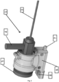
- the invention is built of two main elements - an endoscope assembly 1 ( fig. 1 and fig. 3 ) and an endoscopic camera assembly 2 ( fig. 2 ). These parts are separable as under the conditions of minimally invasive surgical procedure.
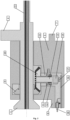
- Endoscope 3 is configured to be connected to an optical adapter 19 via an eyepiece protection window 5 to enable rotation thereof about its own axis (exemplary implementation of such connection is shown in fig. 4 ).
- the endoscope assembly 1 and the endoscopic camera assembly 2 are connected to each other in a manner that prevents their relative rotation, e.g. by a shaped connection. Operator is able to change the optics of the endoscope 3 into the optics of the central axis of the field of view of the endoscope 3 which is parallel or inclined at an angle to the axis of the endoscope 3.
- the endoscope 3 may rotate about the optical axis relative to the housing 6 of the endoscope 3.
- the endoscope assembly 1 comprises an endoscope 3, comprising preferably a fiber optic connection 4, a housing 6 of the endoscope 3 and a system for measuring rotation of the endoscope 3 poisoned within the housing 6 of the endoscope 3.
- the system of measurement of rotation of the endoscope 3 is positioned within the housing 6 of the endoscope 3.
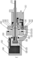
- the movable toothed wheel 10 in an embodiment, is seated on the first end of a shaft 13, the shaft 13 being seated in the housing 6 in a manner to enable rotation, and preferably it is seated via a bearing (15).
- the assembly for measurement of rotation of the endoscope 3 comprises a rotation sensor configured to measure rotation of the shaft 13.
- the assembly for measuring rotation of the endoscope 3 comprises an endoscope interface configured to transfer the measurement data from the rotation sensor.
- the endoscope interface is preferably in a form of an endoscope connector 18.
- the housing 6 of the endoscope 3 comprises a protrusion 8, and the protrusion 8 is intended to mount, in a manner that prevent the housing 6 of the endoscope 3 from rotation, of the endoscope assembly 1 to the endoscopic camera assembly 2. It should be noted that a person skilled in the art will be aware of other methods to attain the aim of preventing rotation of the endoscope assembly 1 relative to the endoscopic camera assembly 2.
- the toothed wheel 9 and the movable wheel 10 are preferably oblique wheels, and the axis of the toothed wheel 9 and the axis of the movable toothed wheel 10 define in a preferable embodiment the right angle.
- the rotation sensor comprises an encoder 17 and a magnet 14 applied on the second end of the shaft 13, which elements perform the function of the rotation sensor configured to measure rotation of the shaft 13.
- the rotation sensor comprises an encoder 17 and a magnet 14 applied on the second end of the shaft 13, which elements perform the function of the rotation sensor configured to measure rotation of the shaft 13.
- the encoder 17 in a preferable embodiment is seated on a printed circuit 16 of the endoscope 3 within the housing 6 of the endoscope 3.
- the endoscope interface is configured to transfer the measurement data from the rotation sensor, and it may also transfer the data stored in a non-volatile memory concerning optical and calibration parameters of the endoscope 3.
- the encoder 17 is seated directly beneath a magnet 14.
- the endoscope assembly 1 may further comprise a play elimination mechanism between the toothed wheel 9 and the movable toothed wheel 10.
- the play elimination mechanism as shown in a preferable embodiment, comprises a spring 12, preferably a spiral spring arranged for applying torque to the shaft 13 and the housing 6. Additionally, between the spring 12 and the shaft 13 there may be arranged a mounting pin 11, to which a spring is mounted 12. It should be emphasized that a person skilled in the art will be aware of other methods for elimination of play.
- the endoscope housing 6 may comprise a rotation limiting mechanism that prevents the endoscope 3 from making a full turn about its own axis relative to the housing 6.
- the rotation limiting mechanism may be implemented via an arm mounted perpendicularly to the axis of the endoscope 3 and an element parallel to the endoscope 3 and protruding above the arm. If the endoscope 3 comprises a fiber optic connection 4, the fiber optic connection 4 may perform the function of the arm.
- the rotation limiting mechanism prevents the endoscope 3 from making a full turn about its own axis relative to the housing 6 via mechanical contact of the portending element of the endoscope 3 with a rotation stop 7.
- the endoscopic camera assembly 2 comprises a housing 29 of the camera where a sensor case 26 of a vision sensor 28 is arranged.
- the endoscopic camera assembly 2 also comprises a camera interface configured to transfer the data from the camera assembly, for example in a form of a camera connector 32.
- the endoscopic camera assembly 2 also comprises an optical adapter 19 configured to connect, for example via a shaped connection by means of a protrusion 8, as shown in an embodiment, to the endoscope 3 of the endoscope assembly 1. This enables transfer of the image from the endoscope 3 to the vision sensor 28. It should be also noted that the optical adapter 19 prevents rotation of the endoscope assembly 1 relative to the axis of the endoscope 3, preferably via a shaped connection with the protrusion 8.
- an adapter case 21 is fixedly mounted onto the optical adapter 19 .
- the camera connector 32 may be arranged on the adapter case 21 or on the camera housing 29.
- the endoscopic camera assembly 2 further comprises a sharpness adjustment knob 20 to enable free adjustment of sharpness by the user.
- the endoscopic camera assembly 2 is additionally configured to measure the position of the sharpness adjustment knob 20 and this is implemented by means of a knob position measurement assembly 20.
- the knob 20 may be made as one element or it may comprise a sharpness adjustment knob 20 and a sharpness adjustment knob cap 24 mounted thereon.
- the endoscopic camera assembly 2 may comprise an accelerometer.
- the assembly for the measurement of the position of the sharpness adjustment knob 20 may be implemented as a reflector 25 and a knob position sensor 23 configured to read out the position of the reflector 25.
- the knob position sensor 23 may be a vision sensor, for example a reflection sensor.
- the knob position sensor 23 in this configuration emits light and measures intensity of the light reflected from the reflector 25 arranged on the sharpness adjustment knob 20.
- the reflector 25 may be positioned on a sidewall of the sharpness adjustment knob 20 and it may be implemented as a sticker with variable optical parameters, e.g. a variable color or brightness, or as a furrow with a variable depth along a section of a circle.
- the knob position sensor 23 is thus used for measurement of the rotation angle of the sharpness rotation knob 20 and this information may be used for setting sharpness in a simulated training in a virtual reality scenario.
- knob position sensor 23 is arranged within the adapter case 21, and preferably the knob position sensor and/or accelerometer are seated on a printed circuit 22 of the optical adapter.
- the optical adapter printed circuit 22 may be positioned for example in the adapter case 21.
- the adapter interface arranged for receiving data from the endoscope interface and to transfer the received data to the camera interface, and preferably the adapter interface is positioned on the optical adapter printed circuit 22.
- the camera printed circuit 30 is attached comprising camera press buttons 31 intended for controlling the endoscopic camera assembly 2. Nevertheless, it should be emphasized that the camera press buttons 31 do not have to be seated in a printed circuit board and they may be affixed directly to the camera housing 29. Moreover, on the optical adapter printed circuit 22 or the camera printed circuit 30 an accelerometer may be arranged to provide absolute measurement of the inclination angle of the endoscopic camera assembly 2 relative to the Earth and its absolute rotation angle about its own axis.
- the endoscopic camera assembly 2 may further comprise an adapter interface configured to receive data from the endoscope interface and to transfer the received data to the camera interface.
- the printed circuit throughout the specification of the invention means a printed circuit board comprising suitable electronic components mounted on the printed circuit board, and not solely the printed circuit board as such.
Landscapes
- Health & Medical Sciences (AREA)
- Life Sciences & Earth Sciences (AREA)
- Engineering & Computer Science (AREA)
- Surgery (AREA)
- Physics & Mathematics (AREA)
- General Health & Medical Sciences (AREA)
- Medical Informatics (AREA)
- Radiology & Medical Imaging (AREA)
- Public Health (AREA)
- Pathology (AREA)
- Biomedical Technology (AREA)
- Heart & Thoracic Surgery (AREA)
- Optics & Photonics (AREA)
- Molecular Biology (AREA)
- Animal Behavior & Ethology (AREA)
- Nuclear Medicine, Radiotherapy & Molecular Imaging (AREA)
- Biophysics (AREA)
- Veterinary Medicine (AREA)
- Multimedia (AREA)
- Signal Processing (AREA)
- General Physics & Mathematics (AREA)
- Chemical & Material Sciences (AREA)
- Mathematical Physics (AREA)
- Algebra (AREA)
- Computational Mathematics (AREA)
- Pulmonology (AREA)
- Mathematical Analysis (AREA)
- Mathematical Optimization (AREA)
- Medicinal Chemistry (AREA)
- Pure & Applied Mathematics (AREA)
- Business, Economics & Management (AREA)
- Educational Administration (AREA)
- Educational Technology (AREA)
- Theoretical Computer Science (AREA)
- Endoscopes (AREA)
Priority Applications (4)
| Application Number | Priority Date | Filing Date | Title |
|---|---|---|---|
| EP23461515.1A EP4414969A1 (fr) | 2023-02-13 | 2023-02-13 | Ensemble endoscope, ensemble caméra endoscopique et dispositif d'endoscopie |
| US18/172,657 US12507872B2 (en) | 2023-02-13 | 2023-02-22 | Endoscope assembly, endoscopic camera assembly and endoscopy device |
| JP2024014219A JP2024114636A (ja) | 2023-02-13 | 2024-02-01 | 内視鏡アセンブリ、内視鏡カメラアセンブリおよび内視鏡装置 |
| CN202410177318.0A CN118486217A (zh) | 2023-02-13 | 2024-02-08 | 内窥镜组件、内窥镜摄像头组件和内窥镜装置 |
Applications Claiming Priority (1)
| Application Number | Priority Date | Filing Date | Title |
|---|---|---|---|
| EP23461515.1A EP4414969A1 (fr) | 2023-02-13 | 2023-02-13 | Ensemble endoscope, ensemble caméra endoscopique et dispositif d'endoscopie |
Publications (1)
| Publication Number | Publication Date |
|---|---|
| EP4414969A1 true EP4414969A1 (fr) | 2024-08-14 |
Family
ID=85285138
Family Applications (1)
| Application Number | Title | Priority Date | Filing Date |
|---|---|---|---|
| EP23461515.1A Pending EP4414969A1 (fr) | 2023-02-13 | 2023-02-13 | Ensemble endoscope, ensemble caméra endoscopique et dispositif d'endoscopie |
Country Status (4)
| Country | Link |
|---|---|
| US (1) | US12507872B2 (fr) |
| EP (1) | EP4414969A1 (fr) |
| JP (1) | JP2024114636A (fr) |
| CN (1) | CN118486217A (fr) |
Citations (5)
| Publication number | Priority date | Publication date | Assignee | Title |
|---|---|---|---|---|
| GB2252656A (en) * | 1991-02-11 | 1992-08-12 | Keymed | Endoscopy training apparatus |
| WO2003096307A1 (fr) * | 2002-05-10 | 2003-11-20 | Haptica Limited | Simulateur d'entraînement chirurgical |
| WO2016000245A1 (fr) * | 2014-07-04 | 2016-01-07 | Covidien Lp | Appareil d'application d'agrafes chirurgicales et procédés pour procédures endoscopiques |
| US20190355278A1 (en) | 2018-05-18 | 2019-11-21 | Marion Surgical Inc. | Virtual reality surgical system including a surgical tool assembly with haptic feedback |
| US20220139260A1 (en) | 2019-02-15 | 2022-05-05 | Virtamed Ag | Compact haptic mixed reality simulator |
Family Cites Families (4)
| Publication number | Priority date | Publication date | Assignee | Title |
|---|---|---|---|---|
| JP3345645B2 (ja) * | 2000-06-20 | 2002-11-18 | 東京大学長 | 体腔内観察装置 |
| WO2005110194A1 (fr) * | 2004-05-14 | 2005-11-24 | Olympus Corporation | Dispositif d'insertion |
| US7896803B2 (en) * | 2005-02-14 | 2011-03-01 | Karl Storz Imaging, Inc. | Variable direction of view instrument with on-board actuators |
| WO2019136172A1 (fr) * | 2018-01-03 | 2019-07-11 | Xenocor, Inc. | Boroscopes coudés avec orientation d'image numérique |
-
2023
- 2023-02-13 EP EP23461515.1A patent/EP4414969A1/fr active Pending
- 2023-02-22 US US18/172,657 patent/US12507872B2/en active Active
-
2024
- 2024-02-01 JP JP2024014219A patent/JP2024114636A/ja active Pending
- 2024-02-08 CN CN202410177318.0A patent/CN118486217A/zh active Pending
Patent Citations (6)
| Publication number | Priority date | Publication date | Assignee | Title |
|---|---|---|---|---|
| GB2252656A (en) * | 1991-02-11 | 1992-08-12 | Keymed | Endoscopy training apparatus |
| WO2003096307A1 (fr) * | 2002-05-10 | 2003-11-20 | Haptica Limited | Simulateur d'entraînement chirurgical |
| EP1504431A1 (fr) | 2002-05-10 | 2005-02-09 | Haptica Limited | Simulateur d'entrainement chirurgical |
| WO2016000245A1 (fr) * | 2014-07-04 | 2016-01-07 | Covidien Lp | Appareil d'application d'agrafes chirurgicales et procédés pour procédures endoscopiques |
| US20190355278A1 (en) | 2018-05-18 | 2019-11-21 | Marion Surgical Inc. | Virtual reality surgical system including a surgical tool assembly with haptic feedback |
| US20220139260A1 (en) | 2019-02-15 | 2022-05-05 | Virtamed Ag | Compact haptic mixed reality simulator |
Also Published As
| Publication number | Publication date |
|---|---|
| US20240268639A1 (en) | 2024-08-15 |
| JP2024114636A (ja) | 2024-08-23 |
| CN118486217A (zh) | 2024-08-13 |
| US12507872B2 (en) | 2025-12-30 |
Similar Documents
| Publication | Publication Date | Title |
|---|---|---|
| US12349985B2 (en) | Device and method for tracking the position of an endoscope within a patient's body | |
| US11116386B2 (en) | Serialization of single-use endoscopes | |
| US6656110B1 (en) | Endoscopic system | |
| EP2811479B1 (fr) | Interface utilisateur pour un système de simulation d'opération chirurgicale | |
| RU2388040C2 (ru) | Управляющее устройство | |
| CN106470634B (zh) | 用于遥控操作医疗系统中的器械的屏外指示的系统和方法 | |
| US8834171B2 (en) | Simulation system for training in endoscopic operations | |
| EP0910997A2 (fr) | Méthode et système de simulation du mouvement de la mâchoire | |
| CN112804940B (zh) | 使用相机的ent工具 | |
| US20050228230A1 (en) | Gravity referenced endoscopic image orientation | |
| JPH0490743A (ja) | 内視鏡装置 | |
| JPH0642644Y2 (ja) | 内視鏡湾曲装置 | |
| EP4414969A1 (fr) | Ensemble endoscope, ensemble caméra endoscopique et dispositif d'endoscopie | |
| WO2009008750A1 (fr) | Simulateur d'endoscope | |
| EP1844696B1 (fr) | Imagerie endoscopique avec indication de la direction de gravité | |
| JP4607043B2 (ja) | 重力方向の表示を伴う内視鏡画像形成方法 | |
| US20060211917A1 (en) | Data generating device and endoscope system | |
| Terry et al. | An integrated port camera and display system for laparoscopy | |
| JP4011888B2 (ja) | 計測内視鏡装置 | |
| EP2811478A1 (fr) | Interface utilisateur pour dispositif de simulation de caméra | |
| CN116829087A (zh) | 用于微创手术工具的双轴控制器、用于微创手术训练的摄像头及用于微创手术训练的系统 | |
| CN218974684U (zh) | 一种腔镜手术仿真的目镜装置 | |
| CA2541759C (fr) | Imagerie endoscopique avec indication de directions de gravite | |
| US20250352286A1 (en) | Apparatus for driving surgical robot system and method thereof | |
| JP2690078B2 (ja) | 内視鏡用色基準具及び内視鏡用色基準装置 |
Legal Events
| Date | Code | Title | Description |
|---|---|---|---|
| PUAI | Public reference made under article 153(3) epc to a published international application that has entered the european phase |
Free format text: ORIGINAL CODE: 0009012 |
|
| STAA | Information on the status of an ep patent application or granted ep patent |
Free format text: STATUS: REQUEST FOR EXAMINATION WAS MADE |
|
| 17P | Request for examination filed |
Effective date: 20230222 |
|
| AK | Designated contracting states |
Kind code of ref document: A1 Designated state(s): AL AT BE BG CH CY CZ DE DK EE ES FI FR GB GR HR HU IE IS IT LI LT LU LV MC ME MK MT NL NO PL PT RO RS SE SI SK SM TR |
|
| STAA | Information on the status of an ep patent application or granted ep patent |
Free format text: STATUS: EXAMINATION IS IN PROGRESS |
|
| 17Q | First examination report despatched |
Effective date: 20251217 |