EP4415084A2 - Système de distribution d'hydrogène et composants de faible poids - Google Patents
Système de distribution d'hydrogène et composants de faible poids Download PDFInfo
- Publication number
- EP4415084A2 EP4415084A2 EP24171871.7A EP24171871A EP4415084A2 EP 4415084 A2 EP4415084 A2 EP 4415084A2 EP 24171871 A EP24171871 A EP 24171871A EP 4415084 A2 EP4415084 A2 EP 4415084A2
- Authority
- EP
- European Patent Office
- Prior art keywords
- mpa
- hydrogen
- range
- mass
- distribution system
- Prior art date
- Legal status (The legal status is an assumption and is not a legal conclusion. Google has not performed a legal analysis and makes no representation as to the accuracy of the status listed.)
- Pending
Links
Images

Classifications
-
- C—CHEMISTRY; METALLURGY
- C22—METALLURGY; FERROUS OR NON-FERROUS ALLOYS; TREATMENT OF ALLOYS OR NON-FERROUS METALS
- C22C—ALLOYS
- C22C38/00—Ferrous alloys, e.g. steel alloys
- C22C38/18—Ferrous alloys, e.g. steel alloys containing chromium
- C22C38/22—Ferrous alloys, e.g. steel alloys containing chromium with molybdenum or tungsten
-
- B—PERFORMING OPERATIONS; TRANSPORTING
- B60—VEHICLES IN GENERAL
- B60K—ARRANGEMENT OR MOUNTING OF PROPULSION UNITS OR OF TRANSMISSIONS IN VEHICLES; ARRANGEMENT OR MOUNTING OF PLURAL DIVERSE PRIME-MOVERS IN VEHICLES; AUXILIARY DRIVES FOR VEHICLES; INSTRUMENTATION OR DASHBOARDS FOR VEHICLES; ARRANGEMENTS IN CONNECTION WITH COOLING, AIR INTAKE, GAS EXHAUST OR FUEL SUPPLY OF PROPULSION UNITS IN VEHICLES
- B60K15/00—Arrangement in connection with fuel supply of combustion engines or other fuel consuming energy converters, e.g. fuel cells; Mounting or construction of fuel tanks
- B60K15/01—Arrangement of fuel conduits
- B60K15/013—Arrangement of fuel conduits of gas conduits
-
- C—CHEMISTRY; METALLURGY
- C21—METALLURGY OF IRON
- C21D—MODIFYING THE PHYSICAL STRUCTURE OF FERROUS METALS; GENERAL DEVICES FOR HEAT TREATMENT OF FERROUS OR NON-FERROUS METALS OR ALLOYS; MAKING METAL MALLEABLE, e.g. BY DECARBURISATION OR TEMPERING
- C21D1/00—General methods or devices for heat treatment, e.g. annealing, hardening, quenching or tempering
- C21D1/26—Methods of annealing
-
- C—CHEMISTRY; METALLURGY
- C21—METALLURGY OF IRON
- C21D—MODIFYING THE PHYSICAL STRUCTURE OF FERROUS METALS; GENERAL DEVICES FOR HEAT TREATMENT OF FERROUS OR NON-FERROUS METALS OR ALLOYS; MAKING METAL MALLEABLE, e.g. BY DECARBURISATION OR TEMPERING
- C21D6/00—Heat treatment of ferrous alloys
- C21D6/002—Heat treatment of ferrous alloys containing Cr
-
- C—CHEMISTRY; METALLURGY
- C21—METALLURGY OF IRON
- C21D—MODIFYING THE PHYSICAL STRUCTURE OF FERROUS METALS; GENERAL DEVICES FOR HEAT TREATMENT OF FERROUS OR NON-FERROUS METALS OR ALLOYS; MAKING METAL MALLEABLE, e.g. BY DECARBURISATION OR TEMPERING
- C21D9/00—Heat treatment, e.g. annealing, hardening, quenching or tempering, adapted for particular articles; Furnaces therefor
- C21D9/08—Heat treatment, e.g. annealing, hardening, quenching or tempering, adapted for particular articles; Furnaces therefor for tubular bodies or pipes
- C21D9/14—Heat treatment, e.g. annealing, hardening, quenching or tempering, adapted for particular articles; Furnaces therefor for tubular bodies or pipes wear-resistant or pressure-resistant pipes
-
- C—CHEMISTRY; METALLURGY
- C22—METALLURGY; FERROUS OR NON-FERROUS ALLOYS; TREATMENT OF ALLOYS OR NON-FERROUS METALS
- C22C—ALLOYS
- C22C38/00—Ferrous alloys, e.g. steel alloys
- C22C38/002—Ferrous alloys, e.g. steel alloys containing In, Mg, or other elements not provided for in one single group C22C38/001 - C22C38/60
-
- C—CHEMISTRY; METALLURGY
- C22—METALLURGY; FERROUS OR NON-FERROUS ALLOYS; TREATMENT OF ALLOYS OR NON-FERROUS METALS
- C22C—ALLOYS
- C22C38/00—Ferrous alloys, e.g. steel alloys
- C22C38/02—Ferrous alloys, e.g. steel alloys containing silicon
-
- C—CHEMISTRY; METALLURGY
- C22—METALLURGY; FERROUS OR NON-FERROUS ALLOYS; TREATMENT OF ALLOYS OR NON-FERROUS METALS
- C22C—ALLOYS
- C22C38/00—Ferrous alloys, e.g. steel alloys
- C22C38/04—Ferrous alloys, e.g. steel alloys containing manganese
-
- C—CHEMISTRY; METALLURGY
- C22—METALLURGY; FERROUS OR NON-FERROUS ALLOYS; TREATMENT OF ALLOYS OR NON-FERROUS METALS
- C22C—ALLOYS
- C22C38/00—Ferrous alloys, e.g. steel alloys
- C22C38/12—Ferrous alloys, e.g. steel alloys containing tungsten, tantalum, molybdenum, vanadium, or niobium
-
- H—ELECTRICITY
- H01—ELECTRIC ELEMENTS
- H01M—PROCESSES OR MEANS, e.g. BATTERIES, FOR THE DIRECT CONVERSION OF CHEMICAL ENERGY INTO ELECTRICAL ENERGY
- H01M8/00—Fuel cells; Manufacture thereof
- H01M8/04—Auxiliary arrangements, e.g. for control of pressure or for circulation of fluids
- H01M8/04082—Arrangements for control of reactant parameters, e.g. pressure or concentration
- H01M8/04201—Reactant storage and supply, e.g. means for feeding, pipes
-
- H—ELECTRICITY
- H01—ELECTRIC ELEMENTS
- H01M—PROCESSES OR MEANS, e.g. BATTERIES, FOR THE DIRECT CONVERSION OF CHEMICAL ENERGY INTO ELECTRICAL ENERGY
- H01M8/00—Fuel cells; Manufacture thereof
- H01M8/04—Auxiliary arrangements, e.g. for control of pressure or for circulation of fluids
- H01M8/04082—Arrangements for control of reactant parameters, e.g. pressure or concentration
- H01M8/04201—Reactant storage and supply, e.g. means for feeding, pipes
- H01M8/04216—Reactant storage and supply, e.g. means for feeding, pipes characterised by the choice for a specific material, e.g. carbon, hydride, absorbent
-
- B—PERFORMING OPERATIONS; TRANSPORTING
- B32—LAYERED PRODUCTS
- B32B—LAYERED PRODUCTS, i.e. PRODUCTS BUILT-UP OF STRATA OF FLAT OR NON-FLAT, e.g. CELLULAR OR HONEYCOMB, FORM
- B32B15/00—Layered products comprising a layer of metal
- B32B15/01—Layered products comprising a layer of metal all layers being exclusively metallic
- B32B15/013—Layered products comprising a layer of metal all layers being exclusively metallic one layer being formed of an iron alloy or steel, another layer being formed of a metal other than iron or aluminium
-
- B—PERFORMING OPERATIONS; TRANSPORTING
- B32—LAYERED PRODUCTS
- B32B—LAYERED PRODUCTS, i.e. PRODUCTS BUILT-UP OF STRATA OF FLAT OR NON-FLAT, e.g. CELLULAR OR HONEYCOMB, FORM
- B32B2311/00—Metals, their alloys or their compounds
- B32B2311/20—Zinc
-
- B—PERFORMING OPERATIONS; TRANSPORTING
- B32—LAYERED PRODUCTS
- B32B—LAYERED PRODUCTS, i.e. PRODUCTS BUILT-UP OF STRATA OF FLAT OR NON-FLAT, e.g. CELLULAR OR HONEYCOMB, FORM
- B32B2597/00—Tubular articles, e.g. hoses, pipes
-
- B—PERFORMING OPERATIONS; TRANSPORTING
- B60—VEHICLES IN GENERAL
- B60K—ARRANGEMENT OR MOUNTING OF PROPULSION UNITS OR OF TRANSMISSIONS IN VEHICLES; ARRANGEMENT OR MOUNTING OF PLURAL DIVERSE PRIME-MOVERS IN VEHICLES; AUXILIARY DRIVES FOR VEHICLES; INSTRUMENTATION OR DASHBOARDS FOR VEHICLES; ARRANGEMENTS IN CONNECTION WITH COOLING, AIR INTAKE, GAS EXHAUST OR FUEL SUPPLY OF PROPULSION UNITS IN VEHICLES
- B60K15/00—Arrangement in connection with fuel supply of combustion engines or other fuel consuming energy converters, e.g. fuel cells; Mounting or construction of fuel tanks
- B60K15/03—Fuel tanks
-
- B—PERFORMING OPERATIONS; TRANSPORTING
- B60—VEHICLES IN GENERAL
- B60K—ARRANGEMENT OR MOUNTING OF PROPULSION UNITS OR OF TRANSMISSIONS IN VEHICLES; ARRANGEMENT OR MOUNTING OF PLURAL DIVERSE PRIME-MOVERS IN VEHICLES; AUXILIARY DRIVES FOR VEHICLES; INSTRUMENTATION OR DASHBOARDS FOR VEHICLES; ARRANGEMENTS IN CONNECTION WITH COOLING, AIR INTAKE, GAS EXHAUST OR FUEL SUPPLY OF PROPULSION UNITS IN VEHICLES
- B60K15/00—Arrangement in connection with fuel supply of combustion engines or other fuel consuming energy converters, e.g. fuel cells; Mounting or construction of fuel tanks
- B60K15/03—Fuel tanks
- B60K2015/03309—Tanks specially adapted for particular fuels
- B60K2015/03315—Tanks specially adapted for particular fuels for hydrogen
-
- C—CHEMISTRY; METALLURGY
- C21—METALLURGY OF IRON
- C21D—MODIFYING THE PHYSICAL STRUCTURE OF FERROUS METALS; GENERAL DEVICES FOR HEAT TREATMENT OF FERROUS OR NON-FERROUS METALS OR ALLOYS; MAKING METAL MALLEABLE, e.g. BY DECARBURISATION OR TEMPERING
- C21D8/00—Modifying the physical properties of ferrous metals or ferrous alloys by deformation combined with, or followed by, heat treatment
- C21D8/10—Modifying the physical properties of ferrous metals or ferrous alloys by deformation combined with, or followed by, heat treatment during manufacturing of tubular bodies
Definitions
- the invention relates to hydrogen-carrying components and low-weight hydrogen distribution systems constructed therefrom, in particular for drive trains of vehicles made of a heat-treatable steel.
- molecular hydrogen (H 2 ) is an ideal fuel for heat engines (e.g. gas turbines and internal combustion engines) and fuel cells.
- H 2 distribution systems e.g. in the drive train of a vehicle or in the fuel supply of a stationary power generation plant
- austenitic stainless steel e.g. type 1.4435, less frequently type 1.4571
- nickel content usually >12.5 mass%.
- This class of material is known to have a face-centered cubic crystal lattice and thus the problem of hydrogen embrittlement, which occurs particularly at high gas pressure, can be avoided (see for example Materials Science and Technology, Volume 33, Issue 13 (2017 )).
- EP 2 850 215 B1 therefore proposes an austenitic steel without molybdenum and with a reduced nickel content of 6 to 9 mass%.
- the mechanical properties of austenitic steel are also often poorly suited to the manufacture of H 2 distribution systems, especially when modern High pressure tanks are used.
- the austenitic stainless steel type 1.4435 usually only has a tensile strength of less than 600 MPa, a 0.2% yield strength of less than 250 MPa and an elongation of more than 45%.
- the typically high weight of H 2 components made from such a material can be a decisive disadvantage, especially for drive trains of modern H 2 -powered vehicles (e.g. cars, trucks, rail vehicles, aircraft, ships, drones, etc.).
- austenitic stainless steels are more difficult to machine and/or require unusual machining processes, so that, for example, for the mass production of H 2 distribution systems for combustion engines or fuel cells, new production facilities have to be installed or existing ones have to be extensively converted.
- the outlined disadvantages of H 2 distribution systems made of austenitic stainless steel represent a significant hurdle for the large-scale use of H 2 energy technology.
- material properties are to be determined in accordance with the relevant industry standards (e.g. ISO 6892-1).
- the term “substant” is to be understood as “within typical design, measurement and / or manufacturing tolerances” . It is also to be understood that depending on whether the quenched and tempered steel is obtained from ores or from recycled material, different accompanying steel elements may be present.
- the hydrogen-carrying component specified above can, for example, be a pipe (see Fig.2 ), a valve (see Fig. 3A and Fig. 3B ), a T-piece, a pressure reducer, a filter, a flow restrictor or a common distributor (e.g. Fig.1 ) or at least combine two of these functions in a common component.
- the base body of the component can be designed in such a way that it can withstand an internal gas pressure of at least 30 MPa, preferably of at least 70 MPa and more preferably of at least 100 MPa during continuous operation.
- the part of the base body which encloses the gas line can have a maximum wall thickness in the range of only 0.8 mm - 9 mm, preferably in the range of 1 mm - 6 mm and more preferably in the range of 1 mm - 5 mm.
- Such components can be used to manufacture H 2 distribution systems that are significantly lighter than the state of the art, but are still resistant to (high) pressure and hydrogen-induced embrittlement and are easy to machine (e.g. CNC milling, drilling, bending and/or welding).
- CNC milling drilling, bending and/or welding
- the tempering steel on the inside of the at least one gas line has a defect depth of at most 5% of the wall thickness.
- the defect depth can have a maximum of 200 ⁇ m, preferably a maximum of 130 ⁇ m.
- the carbon content of the tempering steel of the base body is in the range of 0.18 to 0.33 mass%, preferably in the range of 0.22 to 0.29 mass%.
- the embrittlement resistance of the described components and distribution systems can be further improved by the phosphorus content of the tempering steel being less than or equal to 0.025 mass% and/or the sulfur content of the tempering steel being less than or equal to 0.010 mass%.
- the tensile strength of the tempering steel can be in the range of 700 MPa to 950 MPa, preferably in the range of 750 MPa to 950 MPa, even more preferably in the range of 750 MPa to 900 MPa, and/or the yield strength or the 0.2% proof strength of the quenched and tempered steel is in the range of 600 MPa - 850 MPa, more preferably in the range of 650 MPa to 800 MPa, and/or the elongation at break of the quenched and tempered steel is in the range of 13% to 30%, preferably in the range of 14% to 28% and even more preferably in the range of 15% to 25%.
- the components described can have at least two subunits which are connected by at least one weld and/or at least one soldered connection.
- an outer surface of the base body of the respective component can be coated with at least one of the following coatings: a zinc-nickel coating; a galvanic coating; a coating produced by electrophoretic deposition or a powder coating.
- the selected coating can be corrosion-resistant (e.g. against red rust) for at least 96 hours, preferably for at least 150 hours and more preferably for at least 720 hours in accordance with DIN EN ISO 9227 in order to ensure continuous use of the described components and systems even outdoors and in difficult weather or environmental conditions (e.g. splash water with road salt dissolved in it).
- corrosion-resistant e.g. against red rust
- DIN EN ISO 9227 in order to ensure continuous use of the described components and systems even outdoors and in difficult weather or environmental conditions (e.g. splash water with road salt dissolved in it).
- the material properties of the tempering steel from which the base body of the hydrogen-carrying components described above is essentially made can be achieved, for example, by cold forming a suitable starting material (e.g. a hot pipe or similar semi-finished product) in a first step in order to obtain the desired mechanical strength through the work hardening of the structure.
- a suitable starting material e.g. a hot pipe or similar semi-finished product
- the formed starting material can then be subjected to an annealing process in order to obtain the desired mechanical properties specified above.
- the resulting properties of the material can be determined and suitable semi-finished products selected.
- the present invention provides a hydrogen distribution system for an energy conversion system, which has at least a first hydrogen-carrying component as described above and preferably at least a second hydrogen-carrying component as described above, wherein the two components are in fluid communication with each other - for example via a screw connection, a compression head with a union nut and / or a welded connection and / or a soldered connection.
- such a hydrogen distribution system may comprise a high-pressure section and preferably a low-pressure section and a pressure reducer connecting the high-pressure section to the low-pressure section, wherein the high-pressure section is designed for an operating pressure of at least 30 MPa, preferably of at least 70 MPa and more preferably of at least 100 MPa.
- the high-pressure section can comprise one or more of the following components: an external tank valve or an internal tank valve, a filter, a check valve, a pressure relief valve, at least one filling line and at least one extraction line; a coalescing filter, a T-piece; a filling nozzle, a common distributor and a solenoid valve.
- Such distribution systems are particularly suitable for the drive train of H 2 vehicles such as aircraft, drones, trains, ships or vehicles with H 2 propulsion and / or H 2 power generation plants due to their low weight.
- a stationary or mobile energy conversion system may include the following components; a hydrogen supply line or tank, a hydrogen internal combustion engine, a hydrogen gas turbine, and/or a fuel cell; and a hydrogen distribution system as described above that directs the hydrogen from the supply line or tank to the internal combustion engine, gas turbine, and/or fuel cell.
- an H 2 propulsion system for a vehicle may comprise at least one high-pressure hydrogen tank, a hydrogen combustion engine, a hydrogen gas turbine and/or a fuel cell and a hydrogen distribution system as described above, wherein the hydrogen distribution system directs the hydrogen from the at least one high-pressure hydrogen tank to the internal combustion engine, the gas turbine and / or the fuel cell.
- Fig.1 shows a subsystem of a H 2 high-pressure distribution system for a four-cylinder H 2 internal combustion engine according to an embodiment of the present invention.
- the distribution system comprises a common distributor 110 with two gas inlet connections 112, which are fed via two gas supply lines 120.
- the gas supply lines 120 have a Outer diameter of 10 mm and an inner diameter of 7 mm (see cross section 170 of the gas supply line 120).
- the wall thickness of the two supply lines 120 in this embodiment is therefore 1.5 mm.
- the common distributor 110 can be attached to the internal combustion engine, for example, using fastening blocks 140 (e.g. using screw connections). Since the fastening blocks 140 do not come into contact with the hydrogen, they can also be made of a different material than the base bodies of the hydrogen-carrying components of the H 2 distribution system shown (see section 2 above).
- the common distributor 110 also has four output connections 114, to each of which an H 2 distribution pipe 130 is connected, which conducts H 2 gas to an associated injection device of the associated combustion cylinder (not shown).
- the distribution pipes 130 have an outer diameter of 6.35 mm and an inner diameter of 4 mm. The wall thickness of the distribution pipes 130 is therefore 1.125 mm (see cross section 160 of the distribution pipes 120).
- the distribution system shown and in particular the pipe diameters of the gas supply lines 120 and the distribution pipes 130 are designed for operation with a high-pressure H 2 tank with a gas pressure of 30 MPa.
- the present invention also includes H 2 components and H 2 distribution systems that are designed for higher operating pressures (eg 70 MPa or 100 MPa).
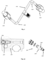
- Fig.2 shows a Z-shaped H 2 distribution pipe 210 according to an embodiment of the present invention.
- the pipe 210 can be connected to other components of an H 2 distribution system via two compression heads 222 with union nuts 220.
- the material properties of the tempering steel from which the base body of the distribution pipe 210 (and possibly the compression heads and union nuts) are made allow the manufacture of strongly bent pipes with tight bending radii without affecting the pressure resistance of the distribution pipe 210.
- the bending radius can be in the range of 1.5 to 2.2 of the pipe diameter.
- the outer surface of the base body of the distribution pipe 210 (and if necessary the outer surfaces of the compression heads 222 and the union nuts 220) is coated coated.
- a zinc-nickel coating, a galvanic coating, a coating produced by electrophoretic deposition (e.g. a cathodic dip coating) or a powder coating can be used for this purpose as described above.
- a coating is corrosion-resistant (e.g. against red rust) for at least 96 hours, more preferably for at least 150 hours and even more preferably for at least 720 hours in accordance with DIN EN ISO 9227.
- Such a coating can also be used for the Fig.1 shown or other H 2 components as described above are used.
- Fig. 3A shows another hydrogen-carrying H 2 component according to another embodiment of the present invention.
- This is a check valve 310, which can be used, for example, in a valve assembly 312 or a filling line (not shown).
- the check valve 310 comprises a valve base body 320 with an axially arranged gas inlet 340 and two radially arranged gas outlets 330 as well as a closure cap 335.
- the valve base body 320 and, if applicable, the closure cap 335 are made of a tempering steel as described in section 2 above. This makes it possible to manufacture check valves with a low wall thickness and good H 2 embrittlement properties that are pressure-resistant and, compared to the state of the art, have a lower weight and are also easy to manufacture.
- the base body 320 of the check valve 310 can, for example, be easily CNC milled and/or drilled without affecting its H 2 compatibility and pressure resistance. In this case, low wall thicknesses (e.g., in the range of 0.8 mm to 5 mm) can be achieved and high pressure resistance in continuous operation and an operating pressure of up to 100 MPa or more can still be guaranteed.
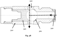
- Fig. 3B shows a longitudinal section through the base body 320 of the check valve 310 of Fig. 3A .
- the gas flow from the gas inlet 340 to the two gas outlets 330 is illustrated by the dashed arrow.
- the valve is closed by a check spring 350 pressing a metallic sealing ball 360 against a sealing surface of the valve body 320. If the H 2 gas pressure exceeds at the gas inlet 340 the sealing pressure provided by the check spring 350, the check valve opens and the H 2 gas can flow from the gas inlet 340 to the two gas outlets 330.
- valve body 320 and, if applicable, the sealing ball 360 and, if applicable, the check spring 350 are made of a tempering steel as described above in section 2. This makes it possible to manufacture H 2 -compatible and high-pressure-resistant check valves (as well as other valve types or H 2 components) that are lightweight and very well suited for mass production.
- the weight reduction and efficiency gains made possible by the present invention can therefore make a substantial contribution to helping environmentally friendly H 2 energy technology achieve a breakthrough.
Landscapes
- Chemical & Material Sciences (AREA)
- Engineering & Computer Science (AREA)
- Mechanical Engineering (AREA)
- Materials Engineering (AREA)
- Organic Chemistry (AREA)
- Metallurgy (AREA)
- Sustainable Development (AREA)
- Life Sciences & Earth Sciences (AREA)
- Sustainable Energy (AREA)
- Crystallography & Structural Chemistry (AREA)
- Thermal Sciences (AREA)
- Physics & Mathematics (AREA)
- Manufacturing & Machinery (AREA)
- Chemical Kinetics & Catalysis (AREA)
- General Chemical & Material Sciences (AREA)
- Electrochemistry (AREA)
- Transportation (AREA)
- Combustion & Propulsion (AREA)
- Filling Or Discharging Of Gas Storage Vessels (AREA)
- Fuel Cell (AREA)
- External Artificial Organs (AREA)
- Transition And Organic Metals Composition Catalysts For Addition Polymerization (AREA)
- Diaphragms For Electromechanical Transducers (AREA)
- Hydrogen, Water And Hydrids (AREA)
Priority Applications (1)
| Application Number | Priority Date | Filing Date | Title |
|---|---|---|---|
| EP24171871.7A EP4415084A3 (fr) | 2021-01-20 | 2021-01-20 | Système de distribution d'hydrogène et composants de faible poids |
Applications Claiming Priority (2)
| Application Number | Priority Date | Filing Date | Title |
|---|---|---|---|
| EP24171871.7A EP4415084A3 (fr) | 2021-01-20 | 2021-01-20 | Système de distribution d'hydrogène et composants de faible poids |
| EP21152585.2A EP4032999B1 (fr) | 2021-01-20 | 2021-01-20 | Système de distribution d'hydrogène et composants de faible poids |
Related Parent Applications (1)
| Application Number | Title | Priority Date | Filing Date |
|---|---|---|---|
| EP21152585.2A Division EP4032999B1 (fr) | 2021-01-20 | 2021-01-20 | Système de distribution d'hydrogène et composants de faible poids |
Publications (2)
| Publication Number | Publication Date |
|---|---|
| EP4415084A2 true EP4415084A2 (fr) | 2024-08-14 |
| EP4415084A3 EP4415084A3 (fr) | 2024-11-13 |
Family
ID=74194591
Family Applications (2)
| Application Number | Title | Priority Date | Filing Date |
|---|---|---|---|
| EP24171871.7A Pending EP4415084A3 (fr) | 2021-01-20 | 2021-01-20 | Système de distribution d'hydrogène et composants de faible poids |
| EP21152585.2A Active EP4032999B1 (fr) | 2021-01-20 | 2021-01-20 | Système de distribution d'hydrogène et composants de faible poids |
Family Applications After (1)
| Application Number | Title | Priority Date | Filing Date |
|---|---|---|---|
| EP21152585.2A Active EP4032999B1 (fr) | 2021-01-20 | 2021-01-20 | Système de distribution d'hydrogène et composants de faible poids |
Country Status (6)
| Country | Link |
|---|---|
| US (1) | US20250297346A1 (fr) |
| EP (2) | EP4415084A3 (fr) |
| JP (1) | JP2024506257A (fr) |
| KR (1) | KR20230169937A (fr) |
| CN (1) | CN117083409A (fr) |
| WO (1) | WO2022157247A1 (fr) |
Families Citing this family (1)
| Publication number | Priority date | Publication date | Assignee | Title |
|---|---|---|---|---|
| EP4361476A1 (fr) * | 2022-10-28 | 2024-05-01 | Poppe & Potthoff GmbH | Clapet anti-retour |
Citations (2)
| Publication number | Priority date | Publication date | Assignee | Title |
|---|---|---|---|---|
| EP2278035B1 (fr) | 2008-05-13 | 2015-09-02 | The Japan Steel Works, Ltd. | Acier faiblement allié à haute résistance, présentant une excellente résistance à la fragilisation dans des milieux d hydrogène à haute pression, et son procédé de fabrication |
| EP2850215B1 (fr) | 2012-05-16 | 2018-01-03 | Bayerische Motoren Werke Aktiengesellschaft | Acier à coût réduit pour la technique de l'hydrogène, à haute résistance contre la fragilisation induite par de l'hydrogène |
Family Cites Families (12)
| Publication number | Priority date | Publication date | Assignee | Title |
|---|---|---|---|---|
| US8020589B2 (en) * | 2007-01-04 | 2011-09-20 | Air Products And Chemicals, Inc. | Hydrogen dispensing station and method of operating the same |
| JP4251229B1 (ja) * | 2007-09-19 | 2009-04-08 | 住友金属工業株式会社 | 高圧水素ガス環境用低合金鋼および高圧水素用容器 |
| JP5356438B2 (ja) * | 2011-03-04 | 2013-12-04 | 株式会社日本製鋼所 | 高圧水素環境下の疲労き裂寿命判定方法 |
| JP2012219949A (ja) * | 2011-04-12 | 2012-11-12 | Honda Motor Co Ltd | 流体供給システム |
| JP5928394B2 (ja) * | 2013-03-29 | 2016-06-01 | Jfeスチール株式会社 | 高圧水素ガス中の耐水素脆化特性に優れた水素用鋼構造物ならびに水素用蓄圧器および水素用ラインパイプの製造方法 |
| CA3077926C (fr) * | 2015-09-17 | 2021-10-26 | Jfe Steel Corporation | Structure d'acier pour l'hydrogene, presentant d'excellentes proprietes de resistance a la fragilisation par l'hydrogene dans l'hydrogene gazeux a haute pression, et son procede d e production |
| JP6648647B2 (ja) * | 2016-07-20 | 2020-02-14 | 日本製鉄株式会社 | 低合金鋼材、低合金鋼管および容器、ならびにその容器の製造方法 |
| JP6490141B2 (ja) * | 2017-05-11 | 2019-03-27 | 株式会社日本製鋼所 | 水素蓄圧器用の低合金鋼および水素蓄圧器 |
| CN106992308B (zh) * | 2017-06-02 | 2018-04-06 | 苏州中氢能源科技有限公司 | 一种燃料电池堆发电系统及控制方法 |
| JP7349776B2 (ja) * | 2018-04-06 | 2023-09-25 | 日本製鉄株式会社 | 高圧水素容器、及び、高圧水素用鋼材 |
| IT201900006429A1 (it) | 2019-04-29 | 2020-10-29 | Omt Digital S R L | Sensore per la diagnostica non invasiva di sistemi idraulici ad alta pressione, in particolare di sistemi di iniezione di combustibile, e sistema idraulico comprendente tale sensore |
| KR20230084555A (ko) | 2020-11-02 | 2023-06-13 | 우수이 고쿠사이 산교 가부시키가이샤 | 고압 수소 배관용 강관 및 그것을 이용한 고압 수소 배관 |
-
2021
- 2021-01-20 EP EP24171871.7A patent/EP4415084A3/fr active Pending
- 2021-01-20 EP EP21152585.2A patent/EP4032999B1/fr active Active
-
2022
- 2022-01-20 US US18/262,307 patent/US20250297346A1/en active Pending
- 2022-01-20 KR KR1020237027715A patent/KR20230169937A/ko active Pending
- 2022-01-20 WO PCT/EP2022/051238 patent/WO2022157247A1/fr not_active Ceased
- 2022-01-20 CN CN202280013287.4A patent/CN117083409A/zh active Pending
- 2022-01-20 JP JP2023544289A patent/JP2024506257A/ja active Pending
Patent Citations (2)
| Publication number | Priority date | Publication date | Assignee | Title |
|---|---|---|---|---|
| EP2278035B1 (fr) | 2008-05-13 | 2015-09-02 | The Japan Steel Works, Ltd. | Acier faiblement allié à haute résistance, présentant une excellente résistance à la fragilisation dans des milieux d hydrogène à haute pression, et son procédé de fabrication |
| EP2850215B1 (fr) | 2012-05-16 | 2018-01-03 | Bayerische Motoren Werke Aktiengesellschaft | Acier à coût réduit pour la technique de l'hydrogène, à haute résistance contre la fragilisation induite par de l'hydrogène |
Non-Patent Citations (1)
| Title |
|---|
| "Materials Science and Technology", vol. 33, 2017 |
Also Published As
| Publication number | Publication date |
|---|---|
| CN117083409A (zh) | 2023-11-17 |
| US20250297346A1 (en) | 2025-09-25 |
| JP2024506257A (ja) | 2024-02-13 |
| EP4032999A1 (fr) | 2022-07-27 |
| EP4032999C0 (fr) | 2024-04-24 |
| EP4032999B1 (fr) | 2024-04-24 |
| KR20230169937A (ko) | 2023-12-18 |
| WO2022157247A1 (fr) | 2022-07-28 |
| EP4415084A3 (fr) | 2024-11-13 |
Similar Documents
| Publication | Publication Date | Title |
|---|---|---|
| DE4311391C2 (de) | Hochdruckkraftstoffeinspritzleitung | |
| DE102013006009B3 (de) | Verfahren zum Herstellen eines Balgs und/oder Balg | |
| DE102004006093B3 (de) | Verfahren zur Herstellung eines dreidimensional geformten Panzerungsbauteils für Fahrzeugkarosserien | |
| DE102004061175A1 (de) | Hochdruckkraftstoffleitung für Dieselmotoren | |
| DE102014102452A1 (de) | Verfahren zur Herstellung von warmgewalzten, nahtlosen Rohren aus umwandlungsfähigem Stahl, insbesondere für Rohrleitungen für Tiefwasseranwendungen und entsprechende Rohre | |
| DE102016115550A1 (de) | Verfahren zur Herstellung eines Kraftstoffverteilers | |
| EP1985919A2 (fr) | Composants grenaillés d'une chaudière ou d'une centrale électrique | |
| EP4032999B1 (fr) | Système de distribution d'hydrogène et composants de faible poids | |
| DE4003384A1 (de) | Dickwandiges kleines verbundmetallrohr und ein verfahren zu dessen herstellung | |
| EP2588731B1 (fr) | Couvercle de carter de palier vissable pour un dispositif de charge | |
| DE112011102945B4 (de) | Abgasturbolader und Krümmermodul | |
| DE102009020490B4 (de) | Dichtungselement zur Abdichtung von Flanschflächen bei Brennkraftmaschinen | |
| DE102020213168A1 (de) | Fluidverteiler für eine Einspritzanlage und Einspritzanlage für gemischverdichtende, fremdgezündete Brennkraftmaschinen | |
| DE102007047016A1 (de) | Hochfester, martensitaushärtbarer Stahl und daraus gebildetes Bauteil | |
| DE102022112321A1 (de) | Verfahren zur Herstellung eines Druckbehälters | |
| DE102021122267A1 (de) | Metallbauteil und Verfahren zu dessen Herstellung | |
| EP1985388A1 (fr) | Poutre métallique résistant aux hautes pressions et son procédé de fabrication | |
| DE2260539A1 (de) | Verfahren zum herstellen von werkstuecken aus legiertem stahl mit gutem mechanischen verhalten in gegenwart von wasserstoff und danach erhaltene werkstuecke | |
| DE102016201337A1 (de) | Wasserstoffführendes Stahlbauteil zum Einsatz bei Kraftfahrzeugen, Kraftfahrzeug mit wasserstoffführendem Stahlbauteil sowie Verfahren zur Herstellung eines wasserstoffführenden Stahlbauteils | |
| EP1709320A2 (fr) | Conduite de stockage haute pression comportant une enveloppe exterieure constituee d'un materiau de moulage pour rampe commune | |
| DE102019213026A1 (de) | Bauteil zum Führen und/oder Speichern von zumindest einem Fluid und Verfahren zu dessen Herstellung | |
| DE102009020416A1 (de) | Flanschverbindung | |
| EP3928016B1 (fr) | Structure tubulaire et procédé pour fabriquer une telle structure tubulaire | |
| DE102019217050A1 (de) | Komponente für eine Einspritzanlage, insbesondere Brennstoffleitung oder Brennstoffverteiler, Einspritzanlage und Verfahren zur Herstellung einer Komponente | |
| DE102023200921A1 (de) | Brennstoffeinblasanlage und Brennstoffverteiler für gasförmige Brennstoffe, insbesondere Wasserstoff |
Legal Events
| Date | Code | Title | Description |
|---|---|---|---|
| PUAI | Public reference made under article 153(3) epc to a published international application that has entered the european phase |
Free format text: ORIGINAL CODE: 0009012 |
|
| STAA | Information on the status of an ep patent application or granted ep patent |
Free format text: STATUS: REQUEST FOR EXAMINATION WAS MADE |
|
| 17P | Request for examination filed |
Effective date: 20240423 |
|
| AC | Divisional application: reference to earlier application |
Ref document number: 4032999 Country of ref document: EP Kind code of ref document: P |
|
| AK | Designated contracting states |
Kind code of ref document: A2 Designated state(s): AL AT BE BG CH CY CZ DE DK EE ES FI FR GB GR HR HU IE IS IT LI LT LU LV MC MK MT NL NO PL PT RO RS SE SI SK SM TR |
|
| REG | Reference to a national code |
Ref country code: DE Ref legal event code: R079 Free format text: PREVIOUS MAIN CLASS: H01M0008040820 Ipc: C22C0038020000 |
|
| PUAL | Search report despatched |
Free format text: ORIGINAL CODE: 0009013 |
|
| AK | Designated contracting states |
Kind code of ref document: A3 Designated state(s): AL AT BE BG CH CY CZ DE DK EE ES FI FR GB GR HR HU IE IS IT LI LT LU LV MC MK MT NL NO PL PT RO RS SE SI SK SM TR |
|
| RIC1 | Information provided on ipc code assigned before grant |
Ipc: B60K 15/03 20060101ALN20241004BHEP Ipc: C21D 8/10 20060101ALN20241004BHEP Ipc: C21D 9/14 20060101ALN20241004BHEP Ipc: C21D 7/02 20060101ALN20241004BHEP Ipc: C21D 6/00 20060101ALN20241004BHEP Ipc: C21D 1/26 20060101ALN20241004BHEP Ipc: C21D 1/25 20060101ALN20241004BHEP Ipc: H01M 8/04082 20160101ALI20241004BHEP Ipc: H01M 8/04089 20160101ALI20241004BHEP Ipc: B60K 15/01 20060101ALI20241004BHEP Ipc: C22C 38/22 20060101ALI20241004BHEP Ipc: C22C 38/12 20060101ALI20241004BHEP Ipc: C22C 38/04 20060101ALI20241004BHEP Ipc: C22C 38/02 20060101AFI20241004BHEP |
|
| STAA | Information on the status of an ep patent application or granted ep patent |
Free format text: STATUS: EXAMINATION IS IN PROGRESS |
|
| 17Q | First examination report despatched |
Effective date: 20260415 |