EP4415111A1 - Batteriekühlender wärmetauscher - Google Patents
Batteriekühlender wärmetauscher Download PDFInfo
- Publication number
- EP4415111A1 EP4415111A1 EP22878368.4A EP22878368A EP4415111A1 EP 4415111 A1 EP4415111 A1 EP 4415111A1 EP 22878368 A EP22878368 A EP 22878368A EP 4415111 A1 EP4415111 A1 EP 4415111A1
- Authority
- EP
- European Patent Office
- Prior art keywords
- side gap
- metal plate
- battery
- closing
- cooling medium
- Prior art date
- Legal status (The legal status is an assumption and is not a legal conclusion. Google has not performed a legal analysis and makes no representation as to the accuracy of the status listed.)
- Pending
Links
Images




Classifications
-
- H—ELECTRICITY
- H01—ELECTRIC ELEMENTS
- H01M—PROCESSES OR MEANS, e.g. BATTERIES, FOR THE DIRECT CONVERSION OF CHEMICAL ENERGY INTO ELECTRICAL ENERGY
- H01M10/00—Secondary cells; Manufacture thereof
- H01M10/60—Heating or cooling; Temperature control
- H01M10/61—Types of temperature control
- H01M10/613—Cooling or keeping cold
-
- F—MECHANICAL ENGINEERING; LIGHTING; HEATING; WEAPONS; BLASTING
- F28—HEAT EXCHANGE IN GENERAL
- F28F—DETAILS OF HEAT-EXCHANGE AND HEAT-TRANSFER APPARATUS, OF GENERAL APPLICATION
- F28F3/00—Plate-like or laminated elements; Assemblies of plate-like or laminated elements
- F28F3/02—Elements or assemblies thereof with means for increasing heat-transfer area, e.g. with fins, with recesses, with corrugations
- F28F3/04—Elements or assemblies thereof with means for increasing heat-transfer area, e.g. with fins, with recesses, with corrugations the means being integral with the element
- F28F3/042—Elements or assemblies thereof with means for increasing heat-transfer area, e.g. with fins, with recesses, with corrugations the means being integral with the element in the form of local deformations of the element
- F28F3/046—Elements or assemblies thereof with means for increasing heat-transfer area, e.g. with fins, with recesses, with corrugations the means being integral with the element in the form of local deformations of the element the deformations being linear, e.g. corrugations
-
- H—ELECTRICITY
- H01—ELECTRIC ELEMENTS
- H01M—PROCESSES OR MEANS, e.g. BATTERIES, FOR THE DIRECT CONVERSION OF CHEMICAL ENERGY INTO ELECTRICAL ENERGY
- H01M10/00—Secondary cells; Manufacture thereof
- H01M10/60—Heating or cooling; Temperature control
- H01M10/62—Heating or cooling; Temperature control specially adapted for specific applications
- H01M10/625—Vehicles
-
- H—ELECTRICITY
- H01—ELECTRIC ELEMENTS
- H01M—PROCESSES OR MEANS, e.g. BATTERIES, FOR THE DIRECT CONVERSION OF CHEMICAL ENERGY INTO ELECTRICAL ENERGY
- H01M10/00—Secondary cells; Manufacture thereof
- H01M10/60—Heating or cooling; Temperature control
- H01M10/64—Heating or cooling; Temperature control characterised by the shape of the cells
- H01M10/647—Prismatic or flat cells, e.g. pouch cells
-
- H—ELECTRICITY
- H01—ELECTRIC ELEMENTS
- H01M—PROCESSES OR MEANS, e.g. BATTERIES, FOR THE DIRECT CONVERSION OF CHEMICAL ENERGY INTO ELECTRICAL ENERGY
- H01M10/00—Secondary cells; Manufacture thereof
- H01M10/60—Heating or cooling; Temperature control
- H01M10/65—Means for temperature control structurally associated with the cells
- H01M10/651—Means for temperature control structurally associated with the cells characterised by parameters specified by a numeric value or mathematical formula, e.g. ratios, sizes or concentrations
-
- H—ELECTRICITY
- H01—ELECTRIC ELEMENTS
- H01M—PROCESSES OR MEANS, e.g. BATTERIES, FOR THE DIRECT CONVERSION OF CHEMICAL ENERGY INTO ELECTRICAL ENERGY
- H01M10/00—Secondary cells; Manufacture thereof
- H01M10/60—Heating or cooling; Temperature control
- H01M10/65—Means for temperature control structurally associated with the cells
- H01M10/655—Solid structures for heat exchange or heat conduction
- H01M10/6554—Rods or plates
-
- H—ELECTRICITY
- H01—ELECTRIC ELEMENTS
- H01M—PROCESSES OR MEANS, e.g. BATTERIES, FOR THE DIRECT CONVERSION OF CHEMICAL ENERGY INTO ELECTRICAL ENERGY
- H01M10/00—Secondary cells; Manufacture thereof
- H01M10/60—Heating or cooling; Temperature control
- H01M10/65—Means for temperature control structurally associated with the cells
- H01M10/655—Solid structures for heat exchange or heat conduction
- H01M10/6556—Solid parts with flow channel passages or pipes for heat exchange
-
- H—ELECTRICITY
- H01—ELECTRIC ELEMENTS
- H01M—PROCESSES OR MEANS, e.g. BATTERIES, FOR THE DIRECT CONVERSION OF CHEMICAL ENERGY INTO ELECTRICAL ENERGY
- H01M10/00—Secondary cells; Manufacture thereof
- H01M10/60—Heating or cooling; Temperature control
- H01M10/65—Means for temperature control structurally associated with the cells
- H01M10/656—Means for temperature control structurally associated with the cells characterised by the type of heat-exchange fluid
- H01M10/6567—Liquids
- H01M10/6568—Liquids characterised by flow circuits, e.g. loops, located externally to the cells or cell casings
-
- F—MECHANICAL ENGINEERING; LIGHTING; HEATING; WEAPONS; BLASTING
- F28—HEAT EXCHANGE IN GENERAL
- F28F—DETAILS OF HEAT-EXCHANGE AND HEAT-TRANSFER APPARATUS, OF GENERAL APPLICATION
- F28F21/00—Constructions of heat-exchange apparatus characterised by the selection of particular materials
- F28F21/08—Constructions of heat-exchange apparatus characterised by the selection of particular materials of metal
-
- F—MECHANICAL ENGINEERING; LIGHTING; HEATING; WEAPONS; BLASTING
- F28—HEAT EXCHANGE IN GENERAL
- F28F—DETAILS OF HEAT-EXCHANGE AND HEAT-TRANSFER APPARATUS, OF GENERAL APPLICATION
- F28F2275/00—Fastening; Joining
- F28F2275/04—Fastening; Joining by brazing
-
- F—MECHANICAL ENGINEERING; LIGHTING; HEATING; WEAPONS; BLASTING
- F28—HEAT EXCHANGE IN GENERAL
- F28F—DETAILS OF HEAT-EXCHANGE AND HEAT-TRANSFER APPARATUS, OF GENERAL APPLICATION
- F28F3/00—Plate-like or laminated elements; Assemblies of plate-like or laminated elements
- F28F3/12—Elements constructed in the shape of a hollow panel, e.g. with channels
-
- Y—GENERAL TAGGING OF NEW TECHNOLOGICAL DEVELOPMENTS; GENERAL TAGGING OF CROSS-SECTIONAL TECHNOLOGIES SPANNING OVER SEVERAL SECTIONS OF THE IPC; TECHNICAL SUBJECTS COVERED BY FORMER USPC CROSS-REFERENCE ART COLLECTIONS [XRACs] AND DIGESTS
- Y02—TECHNOLOGIES OR APPLICATIONS FOR MITIGATION OR ADAPTATION AGAINST CLIMATE CHANGE
- Y02E—REDUCTION OF GREENHOUSE GAS [GHG] EMISSIONS, RELATED TO ENERGY GENERATION, TRANSMISSION OR DISTRIBUTION
- Y02E60/00—Enabling technologies; Technologies with a potential or indirect contribution to GHG emissions mitigation
- Y02E60/10—Energy storage using batteries
Definitions
- the present invention relates to a battery-cooling heat exchanger thermally contacting a vehicle battery to cool the battery.
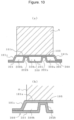
- a battery-cooling heat exchanger As the battery-cooling heat exchanger of this type, a battery-cooling heat exchanger has been well-known, which includes a first metal plate 100 and a second metal plate 200 brazed to each other and is configured such that appropriate recessed and raised portions are formed in the first metal plate 100 and the second metal plate 200 and are combined to form a cavity to be a cooling medium flow path 300 between the first metal plate and the second metal plate (see Patent Literature 1).
- the first metal plate 100 includes a bulging surface 101a which is a flat surface thermally contacting a battery A and a first side wall surface 101b and a second side wall surface 101c formed at both side edges of the bulging surface 101a
- the second metal plate 200 includes a plurality of projections 202a, 202b protruding from a flat portion 201 so as to be joined to the bulging surface 101a and extending along the direction of extension of the cooling medium flow path 300.
- the cavity is divided into a first side gap portion 300a, i.e., a portion formed by the first side wall surface 101b, the projection 202a adjacent thereto, the bulging surface 101a, and the flat portion 201 of the second metal plate 200, a second side gap portion 300b, i.e., a portion formed by the second side wall surface 101c, the projection 202b adjacent thereto, the bulging surface 101a, and the flat portion 201 of the second metal plate 200, and a cooling medium flow portion 300c, i.e., a portion formed by the adjacent projections 202a, 202b, the bulging surface 101a, and the flat portion 201 of the second metal plate 200.
- a first side gap portion 300a i.e., a portion formed by the first side wall surface 101b, the projection 202a adjacent thereto, the bulging surface 101a, and the flat portion 201 of the second metal plate 200
- a second side gap portion 300b i.e., a portion formed by the second side wall
- Patent Literature 1 WO2020/213673
- the cooling medium flows in all the cavities including the side gap portions 300a, 300b on both sides to exchange heat with the battery.
- a margin (brazing portion) which is positioned opposite to the projection 202a, 202b, for joint between the first metal plate 100 and the second metal plate 200 protrudes to a region apart from the bulging surface 101a, and for this reason, an area not contributing to heat exchange with the battery increases in size.
- the battery-cooling heat exchanger is configured without the side gap portions 300a, 300b.
- the recessed and raised portions are formed in the first metal plate 100 and the second metal plate 200 and are combined to form the gap in which the cooling medium flows, it is difficult to omit the side gap portions due to, e.g., a manufacturing error and an assembly error.
- it may be designed such that the side gap portions are formed in an intended manner (the first side wall portion 101b and the projection 202a are separated from each other and the second side wall portion 101c and the projection 202b are separated from each other in an intended manner).
- a battery-cooling heat exchanger including side gap portions with lower efficiencies of heat exchange with a battery A needs to be designed to enhance a battery cooling efficiency.
- the present invention has been made in view of the above-described situation, and a main object thereof is to provide a battery-cooling heat exchanger configured with less heat exchange between a cooling medium and a battery at a portion with a low efficiency of heat exchange with the battery and configured so that the battery can be efficiently cooled.
- a battery-cooling heat exchanger is a battery-cooling heat exchanger 1 thermally contacting a battery A to cool the battery A, including a first metal plate 10 thermally contactable with the battery A and a second metal plate 20 assembled with the first metal plate 10, and causing a cooling medium to flow between the first metal plate 10 and the second metal plate 20.
- the battery-cooling heat exchanger 1 includes an upstream header portion 7 communicating with an inlet 2 through which the cooling medium flows in, a downstream header portion 8 communicating with an outlet 3 through which the cooling medium flows out and separated from the upstream header portion 7, and a plurality of tube forming portions 9 extending so as to cause the upstream header portion 7 and the downstream header portion 8 to communicate with each other, the upstream header portion 7, the downstream header portion 8, and the tube forming portions 9 being formed by the first metal plate 10 and the second metal plate 20.
- a portion of the first metal plate 10 forming each tube forming portion 9 includes a bulging surface 11a bulging toward the battery A, a first side wall surface 11b formed at one side edge of the bulging surface 11a, and a second side wall surface 11c formed at the other side edge of the bulging surface 11a.
- a portion of the second metal plate 20 forming each tube forming portion 9 includes a plurality of projections 22 bulging from a flat portion 21, 21' so as to be joined to the bulging surface 11a and extending along the direction of extension of the tube forming portions 9.
- Each tube forming portion 9 includes one or both of a first side gap portion 30a formed by the first side wall surface 11b, the projection 22 adjacent thereto, the bulging surface 11a, and the flat portion 21 and a second side gap portion 30b formed by the second side wall surface 11c, the projection 22 adjacent thereto, the bulging surface 11a, and the flat portion 21, a cooling medium flow portion 40 formed by each adjacent ones of the projections 22 (22a and 22b, 22b and 22c, 22c and 22d), the bulging surface 11a, and the flat portion 21, 21' between the each adjacent ones of the projections, and one or both of a first closing portion 50a and a second closing portion 50b.
- the width P (P1, P2, P3) of a flow portion heat exchange region of the cooling medium flow portion 40 facing the bulging surface 11a is wider than the width S1 of a first gap portion heat exchange region of the first side gap portion 30a facing the bulging surface 11a and the width S2 of a second gap portion heat exchange region of the second side gap portion 30b facing the bulging surface 11a.
- the first side gap portion 30a is closed with the first closing portion 50a between the upstream header portion 7 and the downstream header portion 8 and the second side gap portion 30b is closed with the second closing portion 50b between the upstream header portion 7 and the downstream header portion 8.
- the width P of the flow portion heat exchange region of the cooling medium flow portion 40 facing the bulging surface is wider than the width S1 of the first gap portion heat exchange region of the first side gap portion 30a facing the bulging surface and the width S2 of the second gap portion heat exchange region of the second side gap portion 30b facing the bulging surface, a great contact area between the battery A and the cooling medium flow portion can be ensured while the side gap portions with a low degree of contribution to heat exchange with the battery A are decreased in size as much as possible, and the efficiency of heat exchange between the battery A and the cooling medium can be enhanced.
- the side gap portions are preferably omitted in order to enhance the heat exchange efficiency.
- the bulging surface and first and second side wall surfaces of the first metal plate and the plurality of projections of the second metal plate are stacked on each other to form the cooling medium flow portion between adjacent ones of the projections.
- the side gap portion still remains at the other side edge.
- the width of the gap portion heat exchange region of the side gap portion facing the bulging surface is set smaller than the width of the flow portion heat exchange region so that the efficiency of heat exchange with the battery can be maintained high.
- first side gap portion is closed with the first closing portion between the upstream header portion and the downstream header portion and the second side gap portion is closed with the second closing portion between the upstream header portion and the downstream header portion, no cooling medium flows from the upstream header portion to the downstream header portion through the side gap portions, and therefore, the entire cooling medium can flow in the cooling medium flow portions to exchange heat with the battery and the efficiency of heat exchange between the battery and the cooling medium can be further enhanced.
- the first closing portion 50a may be formed by a first notch 51a formed in the first metal plate 10 or the second metal plate 20 and protruding to the first side gap portion 30a
- the second closing portion 50b may be formed by a second notch 51b formed in the first metal plate 10 or the second metal plate 20 and protruding to the second side gap portion 30b. Since the closing portions are formed by the notches as described above, the closing portions can be formed at the same time as press-molding of the first metal plate or the second metal plate.
- the cooling medium flow portion 40 may communicate, at one end thereof, with the upstream header portion 7, communicate, at the other end thereof, with the downstream header portion 8, and form, at an intermediate portion thereof, a passage meandering between the vicinity of the upstream header portion 7 and the vicinity of the downstream header portion 8. Since the cooling medium flow portion forms the meandering passage as described above, a temperature difference between a battery installed in the vicinity of the upstream header and a battery installed in the vicinity of the downstream header can be reduced.
- a capacity of cooling the battery in the vicinity of the downstream header is lower as compared to the vicinity of the upstream header.
- the cooling medium flow portion meanders to form the flow path for flowing the cooling medium backward from the downstream header portion toward the upstream header portion, so that the capacity of cooling the battery in the vicinity of the downstream header as compared to the vicinity of the upstream header can be enhanced, temperature distribution can be narrowed in the direction of extension of the tube forming portion, and the temperature distribution of the cells of the entire batteries can be narrowed accordingly.
- the passage resistance of the cooling medium flow portion is relatively increased as compared to a case where the cooling medium flow portion does not meander.
- the cooling heat medium easily flows in the side gap portions.
- the first and second side gap portions are closed with the closing portions 50a, 50b between the upstream header portion and the downstream header portion, such a disadvantage can be effectively avoided.
- the dimension H1 of bulging of the bulging surface 11a of the first metal plate 10 may be set greater than a distance H2 between the bulging surface 11a and the second metal plate 20 in the cooling medium flow portion 40. Since the height of bulging of the bulging surface 11a is higher than the height of the cooling medium flow portion 40, this configuration is applicable to a case where the amount of bulging of the bulging surface is increased to ensure contact with the battery.
- the cooling medium flow portion is formed with a so-called raised bottom so that an increase in the flow path sectional area of the cooling medium flow portion can be suppressed, a decrease in the flow velocity of the cooling medium can be suppressed, and lowering of the heat exchange efficiency in the tube forming portion can be avoided.
- Each tube forming portion 9 preferably has both the first side gap portion 30a and the first closing portion 50a closing the first side gap portion 30a and the second side gap portion 30b and the second closing portion closing the second side gap portion 30b.
- the projections may be formed such that the side gap portions are not formed at the side edges of the tube forming portion 9, but high-accuracy machining is required therefor.
- the notches first notch 51a, second notch 51b
- the side gap portions can be easily closed, without special adjustment, in such a manner that the notches contact the bulging surface and the two side wall surfaces.
- the first closing portion 50a provided for the first side gap portion 30a and the second closing portion 50b provided for the second side gap portion 30b may be provided with a difference in a distance from the upstream header portion 7 or the downstream header portion 8.
- the formation position of the closing portion formed at one side edge and the formation position of the closing portion formed at the other side edge are the same as each other in the direction of extension of the cooling medium flow portion, two relatively-thin portions formed by press-molding are formed at the same position in the extension direction, and for this reason, there is a concern about a lowering of the strength of the tube forming portion.
- the relatively-thin portions are shifted from each other in the extension direction, and therefore, a probability of the strength being lowered can be reduced.
- each tube forming portion 9 may have either the first side gap portion 30a and the first closing portion 50a closing the first side gap portion 30a or the second side gap portion 30b and the second closing portion closing the second side gap portion 30b.
- the side gap portion can be formed only on one side of the tube forming portion in such a manner that the first metal plate 10 and the second metal plate 20 are assembled with the first side wall surface 11b and the projection 22 adjacent thereto or the second side wall surface 11c and the projection 22 adjacent thereto positioned adjacent to each other.
- it is configured such that the side gap portion formed only on one side of the tube forming portion is closed with the closing portion so that the number of side gap portions with a low degree of contribution to heat exchange can be reduced.
- each tube forming portion 9 has one or both of the first side gap portion 30a formed on one side and the second side gap portion formed on the other side and the cooling medium flow portion formed between each adjacent ones of the projections.
- the width of the flow portion heat exchange region of the cooling medium flow portion is wider than the width of the first gap portion heat exchange region of the first side gap portion and the width of the second gap portion heat exchange region of the second side gap portion.
- the first side gap portion is closed with the first closing portion between the upstream header portion and the downstream header portion
- the second side gap portion is closed with the second closing portion between the upstream header portion and the downstream header portion.
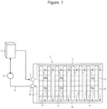
- Fig. 1 is a schematic view of an entire configuration of a battery-cooling heat exchanger according to the present invention and a cooling medium cycle including the battery-cooling heat exchanger.
- Many batteries A indicated by chain lines are placed so as to be thermally coupled onto the battery-cooling heat exchanger 1.
- the battery-cooling heat exchanger 1 includes an inlet 2 through which a cooling medium such as cold water flows in and an outlet 3 through which the cooling medium flows out.
- the inlet 2 and the outlet 3 are connected to an external heat exchanger 5 that cools the cooling medium, such as a chiller, through pipes 4.
- the cooling medium is pressure-fed in the pipe 4 by actuation of a pump 6 installed in the pipe 4.
- the cooling medium is pressure-fed from the pump 6, flows into the external heat exchanger 5, is cooled, flows out of the external heat exchanger 5, flows into the inlet 2, is heated by exchanging heat with the batteries A in the battery-cooling heat exchanger 1, flows out of the outlet 3, and flows into the pump 6 by way of the pipe 4. That is, the cooling medium circulates, while carrying heat, between the battery-cooling heat exchanger 1 and the external heat exchanger 5 by the pump 6 installed in the pipe 4.
- Fig. 2 is a partially-enlarged plan view of a first example of the battery-cooling heat exchanger.
- the battery-cooling heat exchanger 1 has an upstream header portion 7 communicating with the inlet 2, a downstream header portion 8 communicating with the outlet 3, separated from the upstream header portion 7, and extending substantially in parallel with the upstream header portion 7, and a plurality of tube forming portions 9 extending so as to cause the upstream header portion 7 and the downstream header portion 8 to communicate with each other.
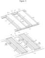
- Fig. 3 is an exploded perspective view of the battery-cooling heat exchanger of Fig. 2 before assembly of a first metal plate 10 and a second metal plate 20.
- the upstream header portion 7, the downstream header portion 8, and the tube forming portions 9 are formed by the first metal plate 10 and the second metal plate 20 assembled therewith.
- the first metal plate 10 and the second metal plate 20 are pressed into predetermined shapes, and thereafter, are joined to each other by a brazing step with stacked on each other.
- Aluminum alloy or copper alloy is preferably used as the materials of the first metal plate 10 and the second metal plate 20. Brazing can be performed.
- the first metal plate 10 includes a plurality of main bulging portions 11 bulging at predetermined intervals with brazing margins and junction bulging portions 12 bulging so as to cause adjacent ones of the main bulging portions 11 to communicate with each other at both end portions thereof, and the second metal plate 20 is formed with the substantially same size as that of the first metal plate 10 and includes projections 22 (described later) on a flat portion 21 formed flat.
- the tube forming portion 9 (see Figs.
- the upstream header portion 7 and the downstream header portion 8 are formed by end portions of the main bulging portions 11 and the junction bulging portions 12 of the first metal plate 10 and the flat portion 21 of the second metal plate 20.
- Fig. 4 is a view showing, from the downstream header portion 8 toward the upstream header portion 7, the section of the tube forming portion 9 in the battery-cooling heat exchanger of Fig. 2 .
- a portion of the first metal plate 10 forming the tube forming portion 9, i.e., the main bulging portion 11, includes a flat bulging surface 11a bulging toward the batteries A, a first side wall surface 11b formed at one side edge of the bulging surface 11a, and a second side wall surface 11c formed at the other side edge of the bulging surface 11a.
- a portion of the second metal plate 20 forming the tube forming portion 9 includes the plurality of projections 22 (22a, 22b, 22c, 22d) bulging so as to be joined to the bulging surface 11a and extending along the direction of extension of the tube forming portion 9.
- the tube forming portion 9 has a first side gap portion 30a formed by the first side wall surface 11b, the projection 22a adjacent thereto, the bulging surface 11a, and the flat portion 21, a second side gap portion 30b formed by the second side wall surface 11c, the projection 22d adjacent thereto, the bulging surface 11a, and the flat portion 21, and a cooling medium flow portion 40 formed by each adjacent ones of the projections 22 (22a and 22b, 22b and 22c, 22c and 22d), the bulging surface 11a, and the flat portion 21 between the each adjacent ones of the projections.
- the cooling medium flow portions 40 are formed as linear passages 40a, 40b, 40c formed in parallel.
- the number of passages is three, but is not limited thereto.
- the number of passages formed for one tube forming portion 9 may be one or more, and is set as appropriate.
- the width P1, P2, P3 of a flow portion heat exchange region of the cooling medium flow portion 40 facing the bulging surface 11a is formed wider than the width S1 of a first gap portion heat exchange region of the first side gap portion 30a facing the bulging surface 11a and the width S2 of a second gap portion heat exchange region of the second side gap portion 30b facing the bulging surface 11a.
- the first side gap portion 30a is closed with a first closing portion 50a (described later) between the upstream header portion 7 and the downstream header portion 8
- the second side gap portion 30b is closed with a second closing portion 50b (described later) between the upstream header portion 7 and the downstream header portion 8.
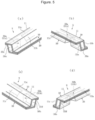
- Fig. 5 is a perspective view showing the closing portion provided for the side gap portion and the vicinity thereof in the battery-cooling heat exchanger of Fig. 2 .
- the first closing portion 50a is formed by a first notch 51a provided in the second metal plate.
- the first notch 51a is a portion protruding from the projection 22a toward the side wall surface 11b so as to close the first side gap portion 30a.
- the second closing portion 50b is formed by a second notch 51b provided for the second metal plate.
- the second notch 51b is a portion protruding from the projection 22d toward the side wall surface 11c so as to close the second side gap portion 30b.
- the notch protrudes so as to contact not only the side wall surface (11b, 11c) but also the bulging surface 11a, and as viewed from the direction of extension of the passage of the cooling medium flow portion 40, is formed with the substantially same sectional shape as that of the side gap portion (first side gap portion 30a, second side gap portion 30b).
- the notch (first notch 51a, second notch 51b) is formed, for example, by a step of pressing the second metal plate 20.
- the first closing portion 50a closing the first side gap portion 30a is provided at a position closer to the upstream header portion 7 with respect to a middle position of the tube forming portion 9 in the direction of extension thereof, and the second closing portion 50b closing the second side gap portion 30b is provided at a position closer to the downstream header portion 8 with respect to the middle position of the tube forming portion 9.
- the cooling medium having flowed in through the inlet 2 flows in the upstream header portion 7, and flows so as to branch into the cooling medium flow portions 40 of each tube forming portion 9.
- the cooling medium flow portions 40 of each tube forming portion 9 are formed as the plurality of linear passages provided in parallel, and therefore, the cooling medium having flowed into each cooling medium flow portion 40 from the upstream header portion 7 moves toward the downstream header portion 8.
- the batteries A and the cooling medium exchange heat through the bulging surfaces 11a contacting the batteries A, and the batteries A are cooled accordingly.
- the cooling medium having flowed in each cooling medium flow portion 40 flows into the downstream header portion 8, is joined together therein, flows out through the outlet 3, and is sent to the external heat exchanger 5.
- the cooling medium also enters both the first side gap portion 30a and the second side gap portion 30b. Since the width S1 of the first gap portion heat exchange region facing the bulging surface 11a and the width S2 of the second gap portion heat exchange region facing the bulging surface 11a in these side gap portions (first side gap portion 30a, second side gap portion 30b) are narrower than the width P1, P2, P3 of the flow portion heat exchange region of each cooling medium flow portion 40 facing the bulging surface 11a, the side gap portion (first side gap portion 30a, second side gap portion 30b) with a low degree of contribution to heat exchange with the batteries A is decreased in size so that a great contact area between the batteries A and the cooling medium flow portion 40 can be ensured. Thus, the efficiency of heat exchange between the batteries A and the cooling medium can be enhanced.
- the heat exchange efficiency is lower accordingly as compared to a case where the cooling medium flows in the cooling medium flow portion 40.
- the first side gap portion 30a is closed with the first closing portion 50a between the upstream header portion 7 and the downstream header portion 8
- the second side gap portion 30b is closed with the second closing portion 50b between the upstream header portion 7 and the downstream header portion 8.
- the side gap portions (first side gap portion 30a, second side gap portion 30b) on both sides, the side gap portions (first side gap portion 30a, second side gap portion 30b) can be easily closed, without special adjustment between the first metal plate 10 and the second metal plate 20, in such a manner that the notches 51a, 52b formed in the second metal plate 20 contact the bulging surface 11a and the two side wall surfaces 11b, 11c.
- first side wall surface 11b and the side surface of the projection 22a facing the first side wall surface 11b and the second side wall surface 11c and the side surface of the projection 22d facing the second side wall surface 11c may be inclined so as to expand outward with distance from the batteries A so that the first metal plate and the second metal plate can be easily assembled with each other.
- first side gap portion 30a, second side gap portion 30b are preferably omitted in order to enhance the heat exchange efficiency, but it is difficult, considering a molding error and an assembly error, to form the projections 22 without the side gap portions (first side gap portion 30a, second side gap portion 30b) at both side edges of each tube forming portion 9. For this reason, even in a case where the side gap portion can be omitted from one side edge of each tube forming portion 9 in such a manner that the overlapping positions of the first metal plate 10 and the second metal plate 20 are adjusted, the side gap portion still remains at the other side edge. Thus, in a case where only either one of the first side gap portion 30a or the second side gap portion 30b is formed, only the closing portion corresponding to such a side gap portion may be formed.
- the first closing portion 50a provided for the first side gap portion 30a and the second closing portion 50b provided for the second side gap portion 30b are provided with a difference in a distance from the upstream header portion 7 or the downstream header portion 8 (difference in a formation position in the direction of extension of the tube forming portion 9), and therefore, the strength of the tube forming portion 9 is not degraded.
- the portions formed with the notches are relatively thin, and strain is accumulated around the notches.
- the first closing portion 50a closing the first side gap portion 30a and the second closing portion 50b closing the second side gap portion 30b are formed at the same position in the direction of extension of the tube forming portion 9, the thin portions are formed at the same position in the extension direction at both side edges of the tube forming portion 9, and there is a concern about lowering of the strength.
- the first notch 51a forming the first closing portion 50a and the second notch 51b forming the second closing portion 50b are provided at different positions in the direction of extension of the tube forming portion 9, and therefore, the relatively-thin portions and the portions where the strain is accumulated are at positions shifted from each other in the extension direction. Thus, a probability of the strength being lowered can be reduced.
- first side gap portion 30a, second side gap portion 30b may be provided for one side gap portion, but in the case of providing two or more closing portions, a closed space where gas (air) is sealed is formed by the adjacent closing portions in the side gap portion.
- the sealed gas and the cooling medium are different from each other in the coefficient of expansion in association with a temperature, and for this reason, there is a concern about unintended stress being caused according to a change in the temperature of the heat exchanger.
- one closing portion is preferably provided for one side gap portion.
- the configuration capable of obtaining a high heat exchange efficiency between the tube forming portion 9 and the batteries A can be provided.
- the cooling medium flowing in the tube forming portion 9 linearly flows from the upstream header portion 7 toward the downstream header portion 8, and therefore, a cell of the battery A closer to the upstream header portion 7 is more cooled relative to a cell of the battery A closer to the downstream header portion 8 and there is a concern about a disadvantage of the entire batteries being not uniformly cooled.
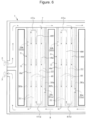
- the shape of the cooling medium flow portion 40 may be designed, as a second example, such that the batteries A are uniformly cooled, as shown in Figs. 6 and 7 . Note that in description of the second example below, the same reference numerals are used to represent elements common to the first example, description thereof will be omitted, and differences from the first example will be mainly described.
- Fig. 6 is a partially-enlarged plan view of the second example of the battery-cooling heat exchanger.
- Fig. 7 is an exploded perspective view of the battery-cooling heat exchanger of Fig. 6 before assembly of a first metal plate and a second metal plate.
- the cooling medium flow portion 40 one end communicates with the upstream header portion 7, the other end communicates with the downstream header portion 8, and an intermediate portion is formed as a passage meandering between the vicinity of the upstream header portion 7 and the vicinity of the downstream header portion 8.
- the cooling medium flow portion 40 has a first flow portion 40a' communicating with the upstream header portion 7 and extending to the vicinity of the downstream header portion 8, a second flow portion 40b' connected to the first flow portion 40a' through a folded-back flow portion 40d and extending from the vicinity of the downstream header portion 8 to the vicinity of the upstream header portion 7, and a third flow portion 40c' connected to the second flow portion 40b' through a folded-back flow portion 40e, extending from the vicinity of the upstream header portion 7, and communicating with the downstream header portion 8, and is entirely formed in an S-shape.
- the cooling medium flowing in the upstream header portion 7 makes one and a half round trips to the downstream header portion 8 in the tube forming portion 9 in the direction of extension thereof, and therefore, the temperature difference between the cell of the battery A installed in the vicinity of the upstream header portion 7 and the cell of the battery A installed in the vicinity of the downstream header portion 8 can be reduced.
- the temperature of the cooling medium flowing in the second flow portion 40b' is lower in the vicinity of the downstream header portion 8 than in the vicinity of the upstream header portion 7, and therefore, a capacity of cooling the batteries A in the vicinity of the downstream header portion as compared to the vicinity of the upstream header portion can be enhanced and the distribution of the temperature of the battery can be narrowed in the direction of extension of the tube forming portion 9.
- the passage resistance of the cooling medium flow portion 40 is relatively higher than those of the first side gap portion 30a and the second side gap portion 30b.
- the cooling medium easily flows in the first side gap portion 30a and the second side gap portion 30b with low heat exchange efficiencies.
- the first side gap portion 30a is closed with the first closing portion 50a and the second side gap portion 30b is closed with the second closing portion 50b, the cooling medium flowing therein can be blocked and lowering of the heat exchange efficiency can be effectively blocked.
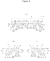
- Fig. 8 is a view showing, from the downstream header portion 8 toward the upstream header portion 7, the section of the tube forming portion 9 in a battery-cooling heat exchanger of a first modification.
- the dimension (H1) of bulging of the bulging surface 11a of the first metal plate 10 is set greater than a distance (H2) between the bulging surface 11a and the second metal plate 20 in the cooling medium flow portion 40.
- a distance between the bulging surface 11a and the second metal plate 20 in the first side gap portion 30a and the second side gap portion 30b is the same as the dimension of bulging of the bulging surface 11a, but is greater than the distance between the bulging surface 11a and the second metal plate 20 in the cooling medium flow portion 40.
- a flat portion 21' forming the lower end of the cooling medium flow portion 40 of the tube forming portion 9 is positioned higher than the flat portion 21 forming the lower ends of the side gap portions 30a, 30b (a so-called raised bottom is formed so that an increase in the depth of the cooling medium passage 40 can be avoided).
- the height (dimension H1 of bulging of the bulging surface 11a) of the main bulging portion 11 is greater than the height (distance H2 between the bulging surface 11a and the second metal plate 20 in the cooling medium flow portion 40) of the cooling medium flow portion 40, and therefore, the first modification is applicable to a case where the amount of bulging of the bulging surface 11a is increased to ensure contact with the batteries A. That is, the battery-cooling heat exchanger can be easily thermally coupled to the batteries A according to the layout of the batteries A mounted on a vehicle.
- the cooling medium flow portion 40 is formed with the so-called raised bottom so that an increase in the flow path sectional area of the cooling medium flow portion 40 can be suppressed, a decrease in the flow velocity of the cooling medium can be suppressed, and lowering of the heat exchange efficiency in the tube forming portion 9 can be avoided.
- closing portions 50a, 50b are formed by the notches 51a, 51b formed in the second metal plate 20
- the closing portions 50a, 50b may be formed by notches formed in the first metal plate 10 or formed by butting notches formed in the first metal plate 10 and the second metal plate 20.
- Fig. 9 is an exploded perspective view of a battery-cooling heat exchanger of a third modification before assembly of the first metal plate 10 and the second metal plate 20.
- the upstream header portion 7 and the downstream header portion 8 described in the first example and the second example are formed by the main bulging portions 11 and the junction bulging portions 12 formed in the first metal plate, but as shown in Fig. 9 , recessed portions 23 may be formed in the second metal plate 20 so as to cause the main bulging portions 11 to communicate with each other and no junction bulging portions 12 may be formed in the first metal plate 10. Alternatively, both the junction bulging portions 12 and the recessed portions 23 may be formed.
Landscapes
- Engineering & Computer Science (AREA)
- Chemical Kinetics & Catalysis (AREA)
- General Chemical & Material Sciences (AREA)
- Electrochemistry (AREA)
- Manufacturing & Machinery (AREA)
- Chemical & Material Sciences (AREA)
- Physics & Mathematics (AREA)
- General Engineering & Computer Science (AREA)
- Mechanical Engineering (AREA)
- Thermal Sciences (AREA)
- Algebra (AREA)
- General Physics & Mathematics (AREA)
- Mathematical Analysis (AREA)
- Mathematical Optimization (AREA)
- Pure & Applied Mathematics (AREA)
- Secondary Cells (AREA)
Applications Claiming Priority (2)
| Application Number | Priority Date | Filing Date | Title |
|---|---|---|---|
| JP2021163939 | 2021-10-05 | ||
| PCT/JP2022/035893 WO2023058498A1 (ja) | 2021-10-05 | 2022-09-27 | バッテリ冷却用熱交換器 |
Publications (2)
| Publication Number | Publication Date |
|---|---|
| EP4415111A1 true EP4415111A1 (de) | 2024-08-14 |
| EP4415111A4 EP4415111A4 (de) | 2025-08-27 |
Family
ID=85804262
Family Applications (1)
| Application Number | Title | Priority Date | Filing Date |
|---|---|---|---|
| EP22878368.4A Pending EP4415111A4 (de) | 2021-10-05 | 2022-09-27 | Batteriekühlender wärmetauscher |
Country Status (4)
| Country | Link |
|---|---|
| EP (1) | EP4415111A4 (de) |
| JP (1) | JPWO2023058498A1 (de) |
| CN (1) | CN117678111A (de) |
| WO (1) | WO2023058498A1 (de) |
Families Citing this family (2)
| Publication number | Priority date | Publication date | Assignee | Title |
|---|---|---|---|---|
| EP4648180A1 (de) * | 2024-05-09 | 2025-11-12 | Aisin Corporation | Wärmetauscher |
| WO2026069797A1 (ja) * | 2024-09-25 | 2026-04-02 | 株式会社三五 | 電池冷却器 |
Family Cites Families (6)
| Publication number | Priority date | Publication date | Assignee | Title |
|---|---|---|---|---|
| JP5659622B2 (ja) * | 2010-08-19 | 2015-01-28 | 株式会社デンソー | 電池パック |
| JP7052578B2 (ja) * | 2018-06-12 | 2022-04-12 | トヨタ自動車株式会社 | 蓄電装置 |
| JP7033730B2 (ja) * | 2018-07-11 | 2022-03-11 | パナソニックIpマネジメント株式会社 | 冷却装置、電池温度調整システム及び車両 |
| JP7324837B2 (ja) * | 2019-04-18 | 2023-08-10 | 株式会社ヴァレオジャパン | 車両用バッテリを冷却するための熱交換器 |
| JP7370128B2 (ja) * | 2019-05-24 | 2023-10-27 | 株式会社ヴァレオジャパン | バッテリー冷却システム |
| JP7314655B2 (ja) * | 2019-06-28 | 2023-07-26 | 株式会社デンソー | 熱交換器 |
-
2022
- 2022-09-27 JP JP2023552812A patent/JPWO2023058498A1/ja active Pending
- 2022-09-27 WO PCT/JP2022/035893 patent/WO2023058498A1/ja not_active Ceased
- 2022-09-27 CN CN202280050383.6A patent/CN117678111A/zh active Pending
- 2022-09-27 EP EP22878368.4A patent/EP4415111A4/de active Pending
Also Published As
| Publication number | Publication date |
|---|---|
| WO2023058498A1 (ja) | 2023-04-13 |
| JPWO2023058498A1 (de) | 2023-04-13 |
| EP4415111A4 (de) | 2025-08-27 |
| CN117678111A (zh) | 2024-03-08 |
Similar Documents
| Publication | Publication Date | Title |
|---|---|---|
| US12460878B2 (en) | Fluid heat exchange systems | |
| CN216790965U (zh) | 热交换器和传热表面 | |
| CN105531819B (zh) | 冷却器及具有该冷却器的半导体装置 | |
| CN102138054B (zh) | 包括热交换器束和壳体的热交换器 | |
| CN109804217B (zh) | 具有空气动力学特征以改善性能的热交换器 | |
| US10451362B2 (en) | Heat exchanger having bypass seal with retention clip | |
| CN215869534U (zh) | 带有用于冷流体分配的跨接通路的热交换器 | |
| JP6693690B2 (ja) | 熱交換器 | |
| US12215933B2 (en) | Compact heat exchanger with wavy fin turbulizer | |
| CN101165332A (zh) | 热交换器 | |
| JP2010056131A (ja) | 液冷式冷却装置 | |
| US20250280509A1 (en) | Cooling device for cooling electronic components | |
| WO2023058498A1 (ja) | バッテリ冷却用熱交換器 | |
| CN111129645B (zh) | 一种换热装置 | |
| JP7393527B2 (ja) | 熱交換器 | |
| JPWO2023058498A5 (de) | ||
| EP3553448B1 (de) | Sekundär angewendetes kaltseitenfeatures für gegossenen wärmetauscher | |
| JP2025518931A (ja) | 動力電池熱交換器、動力電池システム、および電気車両 | |
| CN115235270A (zh) | 包括具有第一和第二内壁的流体管的热交换器 | |
| CN116583985A (zh) | 具有两个大致平行的流动室和三个大致平行的板的冷却器 | |
| JP4164145B2 (ja) | 熱交換器、及びこれを用いたカー・エアコン | |
| JP5471628B2 (ja) | Egrクーラーおよびegrクーラーの製造方法 | |
| JP7723706B2 (ja) | 熱交換器及び動力伝達装置 | |
| KR102866647B1 (ko) | 판형 열교환기 | |
| EP3653984B1 (de) | Flexible verteilerstruktur für plattenrippenwärmetauscher |
Legal Events
| Date | Code | Title | Description |
|---|---|---|---|
| STAA | Information on the status of an ep patent application or granted ep patent |
Free format text: STATUS: THE INTERNATIONAL PUBLICATION HAS BEEN MADE |
|
| PUAI | Public reference made under article 153(3) epc to a published international application that has entered the european phase |
Free format text: ORIGINAL CODE: 0009012 |
|
| STAA | Information on the status of an ep patent application or granted ep patent |
Free format text: STATUS: REQUEST FOR EXAMINATION WAS MADE |
|
| 17P | Request for examination filed |
Effective date: 20240402 |
|
| AK | Designated contracting states |
Kind code of ref document: A1 Designated state(s): AL AT BE BG CH CY CZ DE DK EE ES FI FR GB GR HR HU IE IS IT LI LT LU LV MC MK MT NL NO PL PT RO RS SE SI SK SM TR |
|
| DAV | Request for validation of the european patent (deleted) | ||
| DAX | Request for extension of the european patent (deleted) | ||
| A4 | Supplementary search report drawn up and despatched |
Effective date: 20250729 |
|
| RIC1 | Information provided on ipc code assigned before grant |
Ipc: H01M 10/6556 20140101AFI20250723BHEP Ipc: F28F 3/12 20060101ALI20250723BHEP Ipc: H01M 10/613 20140101ALI20250723BHEP Ipc: H01M 10/625 20140101ALI20250723BHEP Ipc: H01M 10/651 20140101ALI20250723BHEP Ipc: H01M 10/6554 20140101ALI20250723BHEP Ipc: H01M 10/6568 20140101ALI20250723BHEP |
|
| GRAP | Despatch of communication of intention to grant a patent |
Free format text: ORIGINAL CODE: EPIDOSNIGR1 |
|
| STAA | Information on the status of an ep patent application or granted ep patent |
Free format text: STATUS: GRANT OF PATENT IS INTENDED |
|
| INTG | Intention to grant announced |
Effective date: 20260227 |
|
| RAP1 | Party data changed (applicant data changed or rights of an application transferred) |
Owner name: VALEO ELECTRIFICATION |