EP4415215A2 - Flugzeugbatterieladesystem und -verfahren - Google Patents
Flugzeugbatterieladesystem und -verfahren Download PDFInfo
- Publication number
- EP4415215A2 EP4415215A2 EP24156412.9A EP24156412A EP4415215A2 EP 4415215 A2 EP4415215 A2 EP 4415215A2 EP 24156412 A EP24156412 A EP 24156412A EP 4415215 A2 EP4415215 A2 EP 4415215A2
- Authority
- EP
- European Patent Office
- Prior art keywords
- battery
- voltage
- string
- strings
- battery strings
- Prior art date
- Legal status (The legal status is an assumption and is not a legal conclusion. Google has not performed a legal analysis and makes no representation as to the accuracy of the status listed.)
- Pending
Links
Images



Classifications
-
- H—ELECTRICITY
- H02—GENERATION; CONVERSION OR DISTRIBUTION OF ELECTRIC POWER
- H02J—ELECTRIC POWER NETWORKS; CIRCUIT ARRANGEMENTS OR SYSTEMS FOR SUPPLYING OR DISTRIBUTING ELECTRIC POWER; SYSTEMS FOR STORING ELECTRIC ENERGY
- H02J7/00—Circuit arrangements for charging or discharging batteries or for supplying loads from batteries
- H02J7/14—Circuit arrangements for charging or discharging batteries or for supplying loads from batteries for charging batteries from dynamo-electric generators driven at varying speed, e.g. on vehicle
- H02J7/1423—Circuit arrangements for charging or discharging batteries or for supplying loads from batteries for charging batteries from dynamo-electric generators driven at varying speed, e.g. on vehicle with multiple batteries
-
- H—ELECTRICITY
- H02—GENERATION; CONVERSION OR DISTRIBUTION OF ELECTRIC POWER
- H02J—ELECTRIC POWER NETWORKS; CIRCUIT ARRANGEMENTS OR SYSTEMS FOR SUPPLYING OR DISTRIBUTING ELECTRIC POWER; SYSTEMS FOR STORING ELECTRIC ENERGY
- H02J7/00—Circuit arrangements for charging or discharging batteries or for supplying loads from batteries
- H02J7/50—Circuit arrangements for charging or discharging batteries or for supplying loads from batteries acting upon multiple batteries simultaneously or sequentially
-
- B—PERFORMING OPERATIONS; TRANSPORTING
- B64—AIRCRAFT; AVIATION; COSMONAUTICS
- B64D—EQUIPMENT FOR FITTING IN OR TO AIRCRAFT; FLIGHT SUITS; PARACHUTES; ARRANGEMENT OR MOUNTING OF POWER PLANTS OR PROPULSION TRANSMISSIONS IN AIRCRAFT
- B64D27/00—Arrangement or mounting of power plants in aircraft; Aircraft characterised by the type or position of power plants
- B64D27/02—Aircraft characterised by the type or position of power plants
- B64D27/30—Aircraft characterised by electric power plants
- B64D27/33—Hybrid electric aircraft
-
- B—PERFORMING OPERATIONS; TRANSPORTING
- B64—AIRCRAFT; AVIATION; COSMONAUTICS
- B64D—EQUIPMENT FOR FITTING IN OR TO AIRCRAFT; FLIGHT SUITS; PARACHUTES; ARRANGEMENT OR MOUNTING OF POWER PLANTS OR PROPULSION TRANSMISSIONS IN AIRCRAFT
- B64D27/00—Arrangement or mounting of power plants in aircraft; Aircraft characterised by the type or position of power plants
- B64D27/02—Aircraft characterised by the type or position of power plants
- B64D27/30—Aircraft characterised by electric power plants
- B64D27/35—Arrangements for on-board electric energy production, distribution, recovery or storage
- B64D27/357—Arrangements for on-board electric energy production, distribution, recovery or storage using batteries
-
- H—ELECTRICITY
- H02—GENERATION; CONVERSION OR DISTRIBUTION OF ELECTRIC POWER
- H02J—ELECTRIC POWER NETWORKS; CIRCUIT ARRANGEMENTS OR SYSTEMS FOR SUPPLYING OR DISTRIBUTING ELECTRIC POWER; SYSTEMS FOR STORING ELECTRIC ENERGY
- H02J7/00—Circuit arrangements for charging or discharging batteries or for supplying loads from batteries
- H02J7/80—Circuit arrangements for charging or discharging batteries or for supplying loads from batteries including monitoring or indicating arrangements
-
- H—ELECTRICITY
- H02—GENERATION; CONVERSION OR DISTRIBUTION OF ELECTRIC POWER
- H02J—ELECTRIC POWER NETWORKS; CIRCUIT ARRANGEMENTS OR SYSTEMS FOR SUPPLYING OR DISTRIBUTING ELECTRIC POWER; SYSTEMS FOR STORING ELECTRIC ENERGY
- H02J7/00—Circuit arrangements for charging or discharging batteries or for supplying loads from batteries
- H02J7/80—Circuit arrangements for charging or discharging batteries or for supplying loads from batteries including monitoring or indicating arrangements
- H02J7/84—Control of state of health [SOH]
-
- H—ELECTRICITY
- H02—GENERATION; CONVERSION OR DISTRIBUTION OF ELECTRIC POWER
- H02J—ELECTRIC POWER NETWORKS; CIRCUIT ARRANGEMENTS OR SYSTEMS FOR SUPPLYING OR DISTRIBUTING ELECTRIC POWER; SYSTEMS FOR STORING ELECTRIC ENERGY
- H02J7/00—Circuit arrangements for charging or discharging batteries or for supplying loads from batteries
- H02J7/90—Regulation of charging or discharging current or voltage
- H02J7/96—Regulation of charging or discharging current or voltage in response to battery voltage
-
- B—PERFORMING OPERATIONS; TRANSPORTING
- B64—AIRCRAFT; AVIATION; COSMONAUTICS
- B64D—EQUIPMENT FOR FITTING IN OR TO AIRCRAFT; FLIGHT SUITS; PARACHUTES; ARRANGEMENT OR MOUNTING OF POWER PLANTS OR PROPULSION TRANSMISSIONS IN AIRCRAFT
- B64D2221/00—Electric power distribution systems onboard aircraft
-
- B—PERFORMING OPERATIONS; TRANSPORTING
- B64—AIRCRAFT; AVIATION; COSMONAUTICS
- B64D—EQUIPMENT FOR FITTING IN OR TO AIRCRAFT; FLIGHT SUITS; PARACHUTES; ARRANGEMENT OR MOUNTING OF POWER PLANTS OR PROPULSION TRANSMISSIONS IN AIRCRAFT
- B64D35/00—Transmitting power from power plants to propellers or rotors; Arrangements of transmissions
- B64D35/02—Transmitting power from power plants to propellers or rotors; Arrangements of transmissions specially adapted for specific power plants
- B64D35/021—Transmitting power from power plants to propellers or rotors; Arrangements of transmissions specially adapted for specific power plants for electric power plants
- B64D35/022—Transmitting power from power plants to propellers or rotors; Arrangements of transmissions specially adapted for specific power plants for electric power plants of hybrid-electric type
- B64D35/024—Transmitting power from power plants to propellers or rotors; Arrangements of transmissions specially adapted for specific power plants for electric power plants of hybrid-electric type of series type
-
- H—ELECTRICITY
- H02—GENERATION; CONVERSION OR DISTRIBUTION OF ELECTRIC POWER
- H02J—ELECTRIC POWER NETWORKS; CIRCUIT ARRANGEMENTS OR SYSTEMS FOR SUPPLYING OR DISTRIBUTING ELECTRIC POWER; SYSTEMS FOR STORING ELECTRIC ENERGY
- H02J2105/00—Networks for supplying or distributing electric power characterised by their spatial reach or by the load
- H02J2105/30—Networks for supplying or distributing electric power characterised by their spatial reach or by the load the load networks being external to vehicles, i.e. exchanging power with vehicles
- H02J2105/32—Networks for supplying or distributing electric power characterised by their spatial reach or by the load the load networks being external to vehicles, i.e. exchanging power with vehicles for aircrafts
Definitions
- This disclosure relates generally to aircraft batteries and, more particularly, to systems and methods for charging an aircraft battery including a plurality of battery strings electrically connected in parallel.
- Aircraft may include one or more batteries for supplying electrical power to electrical loads of the aircraft or its propulsion system(s). These batteries may be periodically charged to ensure that sufficient electrical power is available for the aircraft's operational requirements.
- Various systems and methods for charging aircraft batteries are known in the art. While these known systems and methods have various advantages, there is still room in the art for improvement.
- an assembly for an aircraft includes a battery, a charger, and a battery monitoring system.
- the battery includes a plurality of battery strings.
- the charger is configured to selectively direct an electrical charging current to the battery to charge the plurality of battery strings.
- the battery monitoring system includes a plurality of sensors. Each sensor is configured to measure a battery string voltage of a respective one of the plurality of battery strings.
- the battery monitoring system further includes a processor in communication with a non-transitory memory storing instructions, which instructions when executed by the processor, cause the processor to determine the battery string voltage for each battery string of the plurality of battery strings with the plurality of sensors, identify a highest-voltage battery string of the plurality of battery strings and a lower-voltage subset of the plurality of battery strings, and sequentially charge each battery string of the lower-voltage subset of the plurality of battery strings with the charger to a first target string voltage.
- the first target string voltage may be greater than a battery string voltage of the highest-voltage battery string.
- the first target string voltage may be within a predetermined voltage threshold of the battery string voltage of the highest-voltage battery string.
- the instructions when executed by the processor, may further cause the processor to charge the highest-voltage battery string and the lower-voltage subset of the plurality of battery strings together to a final target string voltage, subsequent to sequentially charging each battery string of the lower-voltage subset of the plurality of battery strings with the charger to the first target string voltage.
- the final target string voltage may be higher than the first target string voltage
- the lower-voltage subset of the plurality of battery strings may include a plurality of lower-voltage battery strings.
- sequentially charging each battery string of the lower-voltage subset of the plurality of battery strings may include charging only a single battery string at a time.
- the plurality of battery strings may be electrically connected in parallel.
- the assembly may include an aircraft propulsion system gas turbine engine.
- the aircraft propulsion system gas turbine engine may include a generator forming the charger.
- the instructions when executed by the processor, may further cause the processor to sequentially charge each battery string of the lower-voltage subset of the plurality of battery strings with the charger to the first target string voltage and open contactors for each sequentially-charged battery string of the lower-voltage subset of the plurality of battery strings before charging another battery string of the lower-voltage subset of the plurality of battery strings.
- a method for charging a charging a battery for an aircraft includes a plurality of battery strings electrically connected in parallel.
- the method includes determining the battery string voltage for each battery string of the plurality of battery strings, identifying a highest-voltage battery string of the plurality of battery strings and a lower-voltage subset of the plurality of battery strings, sequentially charging each battery string of the lower-voltage subset of the plurality of battery strings with the charger to a first target string voltage, and charging the plurality of battery strings together to a final target string voltage.
- the final target string voltage is greater than the first target string voltage.
- the first target string voltage may be greater than a battery string voltage of the highest-voltage battery string.
- the first target string voltage may be within a predetermined voltage threshold of the battery string voltage of the highest-voltage battery string.
- the method may further include opening contactors for each battery string of the plurality of battery strings prior to determining the battery string voltage for each battery string of the plurality of battery strings.
- sequentially charging each battery string of the lower-voltage subset of the plurality of battery strings may include opening contactors for each sequentially-charged battery string of the lower-voltage subset of the plurality of battery strings before charging another battery string of the lower-voltage subset of the plurality of battery strings.
- an assembly for an aircraft includes an aircraft propulsion system, a battery, a charger, and a battery monitoring system.
- the aircraft propulsion system includes a rotational assembly.
- the rotational assembly includes a rotatable shaft and an electric motor.
- the electric motor is configured to selectively drive the rotatable shaft.
- the battery is configured to provide electrical power to the electric motor to selectively drive the rotatable shaft.
- the battery includes a plurality of battery strings.
- the charger is configured to selectively direct an electrical charging current to the battery to charge the plurality of battery strings.
- the battery monitoring system includes a plurality of sensors. Each sensor is configured to measure a battery string voltage of a respective one of the plurality of battery strings.
- the battery monitoring system further includes a processor in communication with a non-transitory memory storing instructions, which instructions when executed by the processor, cause the processor to determine the battery string voltage for each battery string of the plurality of battery strings with the plurality of sensors, identify a highest-voltage battery string of the plurality of battery strings and a lower-voltage subset of the plurality of battery strings, sequentially charge each battery string of the lower-voltage subset of the plurality of battery strings with the charger to a first target string voltage, and charge the plurality of battery strings together to a final target string voltage.
- the final target string voltage is greater than the first target string voltage.
- the rotational assembly may further include a propeller.
- the electric motor may be configured to selectively drive the propeller via the rotatable shaft.
- the propulsion system may include a gas turbine engine.
- the gas turbine engine may include the rotational assembly and a generator.
- the generator may form the charger.
- the gas turbine engine may include a second rotational assembly including a second rotatable shaft, a bladed turbine rotor, and a bladed compressor rotor.
- the second rotatable shaft may interconnect the bladed turbine rotor and the bladed compressor rotor.
- the bladed turbine rotor may be configured to drive the generator via the second rotatable shaft.
- the plurality of battery strings may be electrically connected in parallel.
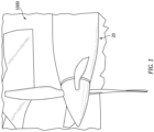
- FIGS. 1 and 2 illustrate a propulsion system 20 configured for an aircraft, such as the aircraft 1000 of FIG. 1 .
- the aircraft may be a fixed-wing aircraft (e.g., an airplane), a rotary-wing aircraft (e.g., a helicopter), a tilt-rotor aircraft, a tilt-wing aircraft, or any other aerial vehicle.
- the aircraft may be a manned aerial vehicle or an unmanned aerial vehicle (UAV, e.g., a drone).
- the aircraft propulsion system 20 of FIG. 2 includes a gas turbine engine 22.
- the present disclosure is also applicable to propulsion systems which do not include gas turbine engines such as, but not limited to, a battery-electric propulsion system (e.g., an electric-motor driven propeller system).
- the propulsion system 20 additionally includes or is otherwise electrically connected to an electrical distribution system 24.
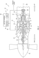
- FIG. 2 illustrates a side, cutaway view of the propulsion system 20 illustrating the gas turbine engine 22 and the electrical distribution system 24.
- the gas turbine engine 22 of FIG. 2 is configured as a hybrid-electric, multi-spool turboprop gas turbine engine.
- gas turbine engines such as, but not limited to, a turboshaft gas turbine engine, a turboprop gas turbine engine, a turbojet gas turbine engine, a propfan gas turbine engine, an open rotor gas turbine engine, an auxiliary power unit (APU), or the like.
- the gas turbine engine 22 of FIG. 2 includes an air inlet 26, a compressor 28, a combustor 30, a high-pressure turbine 32, a power turbine 34, an exhaust 36, and an engine static structure 38.
- the air inlet 26, the compressor 28, the combustor 30, the high-pressure turbine 32, the power turbine 34, and the exhaust 36 are arranged sequentially along an axial centerline 40 (e.g., a rotational axis) of the gas turbine engine 22.
- the engine static structure 38 may include, for example, one or more engine cases for the gas turbine engine 22.
- the engine static structure 38 may additionally include cowlings, bearing assemblies, and/or other structural components of the gas turbine engine 22.
- the one or more engine cases form, house, and/or structurally support one or more of the air inlet 26, the compressor 28, the combustor 30, the high-pressure turbine 32, the power turbine 34, and the exhaust 36.
- Components of the gas turbine engine 22 of FIG. 2 such as components of the compressor 28, the high-pressure turbine 32, and the power turbine 34, are arranged as a first rotational assembly 42 (e.g., a high-pressure spool) and a second rotational assembly 44 (e.g., a power spool).
- the first rotational assembly 42 and the second rotational assembly 44 are mounted for rotation about the axial centerline 40 relative to the engine static structure 38.
- the gas turbine engine 22 of FIG. 2 has a "free turbine" configuration in which power for aircraft propulsion is extracted by the second rotational assembly 44 downstream of (e.g., from the exhaust of) the first rotational assembly 42.
- the present disclosure is not limited to free turbine gas turbine engine configurations.
- the first rotational assembly 42 includes a first shaft 46, a bladed compressor rotor 48 for the compressor 28, and a bladed turbine rotor 50 for the high-pressure turbine 32.
- the first shaft 46 interconnects the bladed compressor rotor 48 and the bladed turbine rotor 50.
- the second rotational assembly 44 includes a second shaft 52, a bladed power turbine rotor 54 for the power turbine 34, and a propeller 56.
- the second shaft 52 is connected to the bladed power turbine rotor 54.
- the second shaft 52 may be directly or indirectly connected to the propeller 56.
- the second shaft 52 may be configured to rotatably drive the propeller 56 via a reduction gear box (RGB) 58.
- RGB reduction gear box
- the second rotation assembly 44 may include additional components (e.g., a propeller input shaft) for interconnecting the second shaft 52 with the bladed power turbine rotor 54 and the propeller 56.
- the RGB 58 may be configured to drive the propeller 56 at a reduced rotational speed relative to the second shaft 52.
- the second shaft 52 may directly interconnect the bladed power turbine rotor 54 and the propeller 56.
- ambient air enters the gas turbine engine 22 through the air inlet 26 and is directed into the compressor 28.
- the ambient air is compressed by the bladed compressor rotor 48 and directed into a combustion chamber 60 of the combustor 30.
- Fuel is injected into the combustion chamber 60 and mixed with the compressed air to provide a fuel-air mixture.
- This fuel-air mixture is ignited, and combustion products thereof flow through and sequentially cause the bladed turbine rotor 50 and the bladed power turbine rotor 54 to rotate.
- the rotation of the bladed turbine rotor 50 and the bladed power turbine rotor 54 respectively drive rotation of the first rotational assembly 42 and the second rotational assembly 44.
- Rotation of the second rotational assembly 44 further drives rotation of the propeller 56 to provide propulsion (e.g., thrust) for the propulsion system 20 and the aircraft 1000 (see FIG. 1 ).
- propulsion e.g., thrust
- Combustion exhaust gas flowing past the bladed power turbine rotor 54 along is directed out of the gas turbine engine 22 through the exhaust 36.
- the electrical distribution system 24 of FIG. 2 is configured to supply electrical power for electrical loads of the propulsion system 20 and/or the aircraft 1000 (see FIG. 1 ).
- Examples of electrical loads for the aircraft 1000 include, but are not limited to, electronic control systems, environmental control systems, electric motors, lighting systems, communication systems, and the like.
- the electrical distribution system 24 of FIG. 2 includes an electric motor 62, a generator 64, an electrical distribution bus 66, and a battery assembly 68.
- the present disclosure is not limited to the particular configuration of the electrical distribution system 24 of FIG. 2 .
- the electric motor 62 is configured to apply a rotational force to second rotational assembly 44.
- the electric motor 62 may be directly or indirectly coupled to the second shaft 52 to drive the second shaft 52 by applying a rotational force to the second shaft 52.
- the electric motor 62 may further include a clutch configured to selectively couple the electric motor 62 to the second shaft 52 or to an intermediate component of the second rotational assembly 44.
- the electric motor 62 may be configured to apply a rotational force to the second rotational assembly 44 to facilitate rotation of the propeller 56 by the second rotational assembly 44.
- the electric motor 62 in combination with the bladed power turbine rotor 54 may provide the rotational force for driving the propeller 56.
- the electric motor 62 may be selected to be sufficiently powerful to drive the propeller 56 during all flight conditions independent of the bladed power turbine rotor 54. Accordingly, the electric motor 62 may provide all of the rotational force for driving the propeller 56.
- the electric motor 62 is electrically connected to the electrical distribution bus 66 and configured to receive electrical power from the electrical distribution bus 66 for operation of the electric motor 62.
- the generator 64 is configured to supply electrical power to the electrical distribution system 24.
- the generator 64 of FIG. 2 is operably coupled to the first shaft 46.
- the generator 64 may be operably coupled to the first shaft 46 by an accessory gear box (not shown) or other speed-reducing gear assembly.
- the first shaft 46 drives rotation of the generator 64 to generate electrical power for the electrical distribution system 24.
- the generator 64 is connected in electrical communication with the electrical distribution bus 66 to supply electrical power to the electrical distribution bus 66 for electrical loads of the propulsion system 20 and/or the aircraft 1000 (see FIG. 1 ).
- the present disclosure is not limited to the particular generator 64 configuration of FIG. 2 .
- the generator 64 may alternatively be operably coupled to and driven by the second shaft 52.
- electrical power for the electrical distribution system 24 may additionally or alternatively be provided by other electrical power sources which are independent of the propulsion system 20 such as, but not limited to, a generator of another propulsion system (e.g., for multi-propulsion-system aircraft), an auxiliary power unit (APU), a fuel cell (e.g., hydrogen fuel cell) assembly, or another power source disposed on the aircraft 1000 or otherwise outside of the propulsion system 20, and/or a ground-based power supply (e.g., an airport electrical distribution system, generator, or other electrical power supply or battery charging device) external to the aircraft 1000.
- a generator of another propulsion system e.g., for multi-propulsion-system aircraft
- APU auxiliary power unit
- fuel cell e.g., hydrogen fuel cell
- ground-based power supply e.g., an airport electrical distribution system, generator, or other electrical power supply or battery charging device
- the battery assembly 68 includes a battery 70 and a battery monitoring system (BMS) 72.
- the battery 70 is configured to selectively supply electrical power to the electrical distribution bus 66 independently (e.g., as a single power source for the electrical distribution bus 66) or in combination with the generator 64 and/or other power sources.
- the battery 70 may be disposed, for example, in the aircraft 1000 and/or its propulsion systems 20.
- the battery 70 of FIG. 3 includes a plurality of battery modules 74 (e.g., battery packs). Each battery module 74 may include a plurality of discrete battery cells electrically connected together (e.g., using series and/or parallel electrical connections) to form the battery module 74.
- the present disclosure is not limited to this particular configuration of the battery modules 74.
- the battery modules 74 e.g., and their battery cells
- Each battery module 74 includes a positive electrode 76 (e.g., an anode) and a negative electrode 78 (e.g., a cathode).
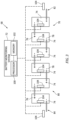
- FIG. 3 schematically illustrates a group of the battery modules 74 electrically connected in series to form a battery string 80 of the battery 70.
- each battery module 74 of the battery string 80 of FIG. 3 is electrically connected in series (e.g., positive to negative or negative to positive) to one or more other battery modules 74 of the battery string 80 of FIG. 3 .
- the battery string 80 includes a positive string terminal 82 and a negative string terminal 84 for connecting the battery string 80 in electrical communication with other portions of the battery 70.
- the battery string 80 of FIG. 3 includes six (6) battery modules 74 electrically connected in series.
- the present disclosure is not limited to any particular number of battery modules 74 for the battery string 80.
- the battery modules 74 of the battery string 80 may be electrically connected together using series and/or parallel electrical connections as necessary to configure the battery string 80 with the desired electrical characteristics (e.g., voltage output, power output, etc.) for the battery string 80.
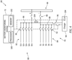
- FIG. 4 schematically illustrates a portion of the battery assembly 68 in which the battery 70 includes a plurality of the battery strings 80.
- the plurality of battery strings 80 of FIG. 4 includes five (5) battery strings S1-5 electrically connected together in parallel.
- the positive string terminals 82 e.g., S1+, S2+, S3+, S4+, S5+
- the negative string terminals 84 e.g., S1-, S2-, S3-, S4-, S5-
- Each battery string 80 of FIG. 4 includes a positive string contactor 90 and a negative string contactor 92.
- the positive string contactor 90 for each battery string 80 is disposed at (e.g., on, adjacent, or proximate) the respective positive string terminal 82 or otherwise electrically between the respective positive string terminal 82 and the positive battery terminal 86.
- the positive string contactor 90 is selectively positionable in a closed position or an open position. In the closed position, the positive string contactor 90 is configured to convey electrical current between the positive battery terminal 86 and the respective positive string terminal 82. In the open position, the positive string contactor 90 is configured to interrupt (e.g., obstruct, prevent, etc.) electrical current between the positive battery terminal 86 and the respective positive string terminal 82.
- the negative string contactor 92 for each battery string 80 is disposed at (e.g., on, adjacent, or proximate) the respective negative string terminal 84 or otherwise electrically between the respective negative string terminal 84 and the negative battery terminal 88.
- the negative string contactor 92 is selectively positionable in a closed position or an open position. In the closed position, the negative string contactor 92 is configured to convey electrical current between the negative battery terminal 88 and the respective negative string terminal 84. In the open position, the negative string contactor 92 is configured to interrupt (e.g., obstruct, prevent, etc.) electrical current between the negative battery terminal 88 and the respective negative string terminal 84.
- the positive string contactor 90 and the negative string contactor 92 may be controlled to selectively electrically connect or selectively electrically disconnect the respective battery string 80 from the battery terminals 86, 88 and/or the electrical distribution bus 66.
- the positive string contactor 90 and the negative string contactor 92 may be configured as electrically-controlled relays or switches which may be controlled by an electrical control signal to position the respective positive string contactor 90 and negative string contactor 92 in the closed position or the open position. While each battery string 80 of FIG.
- the present disclosure is not limited to the use of both the positive string contactor 90 and the negative string contactor 92 for the battery string 80 (e.g., the battery string 80 may include the positive string contactor 90 or the negative string contactor 92).
- the battery 70 may alternatively include other selective electrical power interruption devices such as, but not limited to electrical circuit breakers or electrical switches.
- the battery 70 of FIG. 4 further includes a charger 94, main charger contactors 96, and main battery contactors 98.
- the charger 94 is an electrical power source configured to supply electrical power to the battery terminals 86, 88 for charging one or more of the battery strings 80 (e.g., the battery strings S1, S2, S3, S4, and/or S5 of FIG. 4 ).
- the charger 94 may be formed by or may otherwise include one or more electrical power sources such as, but not limited to, the generator 64, a generator of another propulsion system (e.g., for multi-propulsion-system aircraft), an auxiliary power unit (APU), a fuel cell (e.g., hydrogen fuel cell) assembly, or another power source disposed on the aircraft 1000 or otherwise outside of the propulsion system 20, and/or a ground-based power supply (e.g., an airport electrical distribution system, generator, or other electrical power supply or battery charging device) external to the aircraft 1000.
- the main charger contactors 96 are configured to selectively connect the charger 94 in electrical communication with the battery 70 (e.g., with the positive battery terminal 86 and the negative battery terminal 88).
- the main battery contactors 98 are configured to selectively connect the electrical distribution bus 66 in electrical communication with the battery 70 (e.g., with the positive battery terminal 86 and the negative battery terminal 88).
- Each of the main charger contactors 96 and the main battery contactors 98 is selectively positionable in a closed position or an open position. In the closed position, each of the main charger contactors 96 and the main battery contactors 98 is configured to convey electrical current. In the open position, each of the main charger contactors 96 and the main battery contactors 98 is configured to interrupt (e.g., obstruct, prevent, etc.) electrical current.
- the main charger contactors 96 and the main battery contactors 98 may be configured as electrically-controlled relays or switches which may be controlled by an electrical control signal to position the main charger contactors 96 and the main battery contactors 98 in their respective closed position or open position.
- the battery monitoring system 72 of FIGS. 2-4 includes a processor 100 and memory 102.
- the memory 102 is in signal communication with the processor 100.
- the processor 100 may include any type of computing device, computational circuit, or any type of process or processing circuit capable of executing a series of instructions that are stored in the memory 102, thereby causing the processor 100 to perform or control one or more steps or other processes.
- the processor 100 may include multiple processors and/or multicore CPUs and may include any type of processor, such as a microprocessor, digital signal processor, co-processors, a microcontroller, a microcomputer, a central processing unit, a field programmable gate array, a programmable logic device, a state machine, logic circuitry, analog circuitry, digital circuitry, etc., and any combination thereof.
- the instructions stored in memory 102 may represent one or more algorithms for controlling and/or monitoring aspects of the battery assembly 68, and the stored instructions are not limited to any particular form (e.g., program files, system data, buffers, drivers, utilities, system programs, etc.) provided they can be executed by the processor 100.
- the memory 102 may be a non-transitory computer readable storage medium configured to store instructions that when executed by one or more processors, cause the one or more processors to perform or cause the performance of certain functions.
- the memory 102 may be a single memory device or a plurality of memory devices.
- a memory device may include a storage area network, network attached storage, as well a disk drive, a read-only memory, random access memory, volatile memory, non-volatile memory, static memory, dynamic memory, flash memory, cache memory, and/or any device that stores digital information.
- One skilled in the art will appreciate, based on a review of this disclosure, that the implementation of the battery monitoring system 72 may be achieved via the use of hardware, software, firmware, or any combination thereof.
- the battery monitoring system 72 may also include input and output devices (e.g., keyboards, buttons, switches, touch screens, video monitors, sensor readouts, data ports, etc.) that enable the operator to input instructions, receive data, etc.
- the battery monitoring system 72 includes a plurality of sensors 104 to monitor operational parameters of the battery 70 including, but not limited to, voltage, current, and temperature.
- the battery monitoring system 72 may include one or more of the sensors 104 at (e.g., on, adjacent, or proximate) each battery module 74 to monitor the health of each battery module 74 and or to monitor operational parameters of each battery module 74 such as, but not limited to, voltage, current, and temperature.
- the battery monitoring system 72 may additionally include one or more sensors 104 for monitoring voltage and current parameters for each battery string 80, for the battery 70 (e.g., at the battery terminals 86, 88), and/or for the charger 94.
- the battery monitoring system 72 may be connected in electrical and/or electronic communication with the string contactors 90, 92.
- the battery monitoring system 72 may control the string contactors 90, 92 for positioning in their respective open positions or closed positions using a control signal (e.g., a control current, electronic signal, etc.).
- the battery monitoring system 72 may be connected in electrical and/or electronic communication with the main charger contactors 96 and/or the main battery contactors 98 to control the main charger contactors 96 and/or the main battery contactors 98 in their respective open positions or closed positions.
- the main battery contactors 98 may be controlled independent of the battery monitoring system 72, for example, manually (e.g., by a pilot or other operator) or by another control system of the propulsion system 20 or the aircraft (see FIG. 1 ).
- FIG. 5 illustrates a flowchart for the Method 500.
- the Method 500 may be performed for the battery assembly 68, as described herein.
- the battery monitoring system 72 may be used to execute or control one or more steps of the Method 500 for the battery 70.
- the processor 100 may execute instructions stored in memory 102, thereby causing the battery monitoring system 72 and/or its processor 100 to execute or otherwise control one or more steps of the Method 500.
- the Method 500 is not limited to use with the battery assembly 68 described herein. Unless otherwise noted herein, it should be understood that the steps of Method 500 are not required to be performed in the specific sequence in which they are discussed below and, in some embodiments, the steps of Method 500 may be performed separately or simultaneously.
- Step 502 includes opening (e.g., as controlled by the battery monitoring system 72) the string contactors 90, 92 for each battery string 80 of the plurality of battery strings 80.
- Step 502 may include opening the string contactors 90, 92 for all of the battery strings 80 of the battery 70.
- Step 504 includes closing (e.g., as controlled by the battery monitoring system 72) the string contactors 90, 92 for a selected battery string 80, which selected battery string 80 is one of the plurality of battery strings 80.
- the selected battery string 80 may be any battery string 80 of the plurality of battery strings 80 which is identified by the battery monitoring system 72 as having a battery string voltage V STRING which is less than a full charging voltage or another target string voltage V TARGET for the battery string 80.
- FIG. 6 graphically illustrates the battery string voltages V STRING for each of the battery strings 80 of FIG. 4 including the battery strings S1, S2, S3, S4, and S5.
- the battery string S2 is the selected battery string 80 and the string contactors 90, 92 for the battery string S2 have been closed to allow the battery string S2 to receive a charging current from the charger 94.
- Step 506 includes charging the selected battery string 80 (e.g., only the selected battery string 80) to a target string voltage V TARGET using the charger 94.
- Electrical charging current from the charger 94 is directed to the selected battery string 80 to charge the selected battery string 80.
- the battery string voltage V STRING of the selected battery string 80 will increase.
- the charging current from the charger 94 may be constant or substantially constant for most of the charging of the selected battery string 80.
- the charging current from the charger 94 may be reduced as the battery string voltage V STRING increases to near a full charge voltage for the selected battery string 80.
- the battery monitoring system 72 may monitor the battery string voltage V STRING of the selected battery string 80 to continue charging the selected battery string 80 until the battery string voltage V STRING increases to the target string voltage V TARGET .
- Step 508 includes opening (e.g., as controlled by the battery monitoring system 72) the string contactors 90, 92 for the selected battery string 80.
- the string contactors 90, 92 for the selected battery string 80 may be opened by the battery monitoring system 72 when the battery monitoring system 72 identifies that charging of the selected battery string 80 is complete (e.g., selected battery string voltage V STRING is above, at, or within a threshold tolerance of the target string voltage V TARGET ).
- Steps 504, 506, and 508 may be repeated for each other battery string 80 of the plurality of battery strings 80. For example, Steps 504, 506, and 508 may be repeated until all of the battery strings 80 of the battery 70 have been charged.
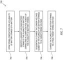
- FIG. 7 illustrates a flowchart for the Method 700.
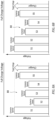
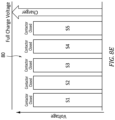
- FIGS. 8A-E illustrate graphs of battery string voltages V STRING of the plurality of battery strings 80 at various stages for a battery charged using the Method 700.
- the Method 700 may be performed for the battery assembly 68, as described herein.
- the battery monitoring system 72 may be used to execute or control one or more steps of the Method 700 for the battery 70.
- the processor 100 may execute instructions stored in memory 102, thereby causing the battery monitoring system 72 and/or its processor 100 to execute or otherwise control one or more steps of the Method 700.
- the Method 700 is not limited to use with the battery assembly 68 described herein. Unless otherwise noted herein, it should be understood that the steps of Method 700 are not required to be performed in the specific sequence in which they are discussed below and, in some embodiments, the steps of Method 700 may be performed separately or simultaneously.
- Step 702 includes opening (e.g., as controlled by the battery monitoring system 72) the string contactors 90, 92 for each battery string 80 of the plurality of battery strings 80.
- Step 502 may include opening the string contactors 90, 92 for all of the battery strings 80 of the battery 70.
- Step 704 includes identifying one battery string 80 of the plurality of battery strings 80 having the highest battery string voltage V STRING (e.g., the "highest-voltage battery string") for the plurality of battery strings 80.
- Step 704 may first include determining or otherwise obtaining, with the battery monitoring system 72 (e.g., the sensors 104), the battery strong voltage V STRING for each battery string 80 of the plurality of battery strings 80.
- Each battery string 80 of the plurality of battery strings 80 other than the identified highest-voltage battery string 80 may be understood as a "lower-voltage battery string.”
- the battery string S1 may be understood as the highest-voltage battery string.
- the battery strings S2-5 may be understood to be lower-voltage battery strings.
- the lower-voltage battery strings S2-5 may, therefore, form a lower-voltage subset of the plurality of battery strings 80.
- Step 706 includes sequentially charging the lower-voltage subset of the plurality of battery strings 80.
- Step 706 may include sequentially charging each lower-voltage battery string individually to a target string voltage V TARGET until all of the lower-voltage battery strings have been charged to the target string voltage V TARGET .
- the target string voltage V TARGET is greater than the battery string voltage V STRING of the highest-voltage battery string (e.g., battery string S1 of FIGS. 8A-E ).
- the target string voltage V TARGET may be within a voltage tolerance (e.g., a predetermined voltage tolerance) of the battery string voltage V STRING of the highest-voltage battery string.
- Charging each lower-voltage battery string to a target string voltage V TARGET just above the battery string voltage V STRING of the highest-voltage battery string may minimize the difference in the open-circuit voltages of the battery strings 80, thereby reducing the likelihood of damaged electrical equipment (e.g., contactors) or electrical arcs when the battery strings 80 are electrically connected in parallel.
- Routine experimentation may be performed by a person of ordinary skill in the art to determine a suitable voltage tolerance for charging the battery strings 80 in accordance with and as informed by one or more aspects of the present disclosure.
- the voltage tolerance may be a voltage range between and to 95% and 105% of the target string voltage V TARGET .
- Each battery string 80 selected by the battery monitoring system 72 for charging may be charged (e.g., as controlled by the battery monitoring system 72) by closing (e.g., if open) the string contactors 90, 92 for the selected battery string 80, closing (e.g., if open) the main charger contactors 96, 98 for the charger 94, and directing an electrical charging current from the charger 94 to the selected battery string 80.
- FIGS. 8A-D illustrate an exemplary sequence for charging the lower-voltage subset of the plurality of battery strings 80.
- the battery string S2 is the selected battery string.
- the battery string S2 is charged by closing the string contactors 90, 92 for the battery string S2 and directing the electrical charging current from the charger 94 to the battery string S2.
- the string contactors 90, 92 for each other battery string S1, S3-5 may be open such that only the battery string S2 may be charged.
- the first battery string S2 is charged to the target string voltage V TARGET which, as previously discussed, is greater than the battery string voltage V STRING of the highest-voltage battery string (e.g., battery string S1 of FIGS. 8A-E ).
- the string contactors 90, 92 for the battery string S2 may be opened.
- the battery monitoring system 72 may identify that a voltage difference between the previously charged battery string(s) (e.g., the battery string S2) and a next battery string to be charged (e.g., the battery string S3 as the selected battery string; see FIG 8B ) is within a threshold voltage limit such that the string contactors 90, 92 for the selected string S3 may be closed without opening the string contactors 90, 92 for the previously charged battery string(s) (e.g., the battery string S2).
- the threshold voltage limit may be a predetermined or dynamically determined value selected to prevent the battery strings 80 from exceeding electrical current and/or temperature limits.
- Maintaining the string contactors 90, 92 for multiple battery strings 80 in their closed positions during the charging sequence of Step 706 may facilitate maintaining the multiple battery strings 80 with an equalized charge level (e.g., equalized battery string voltage V STRING ) during the charging sequence.
- the remaining battery strings S3-5 of the lower-voltage subset of the plurality of battery strings 80 are sequentially charged similar to that described above with respect to the battery string S2, by closing the contactors 90, 92 for the respective battery string S3-5, charging the respective battery string S3-5 to the target string voltage V TARGET , and optionally opening the contactors 90, 92 for the respective battery string S3-5.
- Step 708 may include charging each battery string 80 of the plurality of battery strings 80 to a final target string voltage V FINAL .
- the plurality of battery strings 80 may be charged to the final target string voltage V FINAL by closing the string contactors 90, 92 for each battery string 80 of the plurality of battery strings 80 and directing the electrical charging current from the charger 94 to the plurality of battery strings 80.
- the final target string voltage V FINAL may be greater than the target string voltage V TARGET .
- the final target string voltage V FINAL may be a maximum charging voltage or near a maximum charging voltage for the plurality of battery strings 80. As shown in FIG.
- Step 708 may be performed to charge each battery string 80 together to the final target string voltage V FINAL subsequent to charging the lower-voltage subset of the plurality of battery strings 80 to the target string voltage V TARGET .
- the sequential charging process of Step 706 facilitates more rapid charging for batteries having multiple battery strings connected in parallel. Moreover, this sequential charging process may more rapidly charge battery strings of a battery to greater than the minimum operational voltage for each battery string, thereby maximizing the number of battery strings which may be available for use during aircraft maneuvers requiring battery energy (e.g., for greater propulsion system thrust).
- any one of these structures may describe the operations as a sequential process, many of the operations can be performed in parallel or concurrently.
- the order of the operations may be rearranged.
- a process may correspond to a method, a function, a procedure, a subroutine, a subprogram, etc.
Landscapes
- Engineering & Computer Science (AREA)
- Power Engineering (AREA)
- Aviation & Aerospace Engineering (AREA)
- Charge And Discharge Circuits For Batteries Or The Like (AREA)
- Secondary Cells (AREA)
- Health & Medical Sciences (AREA)
- General Health & Medical Sciences (AREA)
- Medical Informatics (AREA)
Applications Claiming Priority (1)
| Application Number | Priority Date | Filing Date | Title |
|---|---|---|---|
| US202363443882P | 2023-02-07 | 2023-02-07 |
Publications (2)
| Publication Number | Publication Date |
|---|---|
| EP4415215A2 true EP4415215A2 (de) | 2024-08-14 |
| EP4415215A3 EP4415215A3 (de) | 2024-08-21 |
Family
ID=89854594
Family Applications (1)
| Application Number | Title | Priority Date | Filing Date |
|---|---|---|---|
| EP24156412.9A Pending EP4415215A3 (de) | 2023-02-07 | 2024-02-07 | Flugzeugbatterieladesystem und -verfahren |
Country Status (3)
| Country | Link |
|---|---|
| US (1) | US20240333020A1 (de) |
| EP (1) | EP4415215A3 (de) |
| CA (1) | CA3228442A1 (de) |
Family Cites Families (3)
| Publication number | Priority date | Publication date | Assignee | Title |
|---|---|---|---|---|
| JP5859341B2 (ja) * | 2012-02-28 | 2016-02-10 | 三菱重工業株式会社 | 電圧均等化装置及び方法並びにプログラム、それを備えた電力貯蔵システム |
| KR102734149B1 (ko) * | 2019-10-14 | 2024-11-25 | 주식회사 엘지에너지솔루션 | 개별 팩간 에너지 차이를 이용한 병렬 전지팩 충전방법 및 시스템 |
| US20220029431A1 (en) * | 2020-07-23 | 2022-01-27 | Aurora Flight Sciences Corporation, a subsidiary of The Boeing Company | Switchable Battery Management System |
-
2024
- 2024-02-07 US US18/435,580 patent/US20240333020A1/en active Pending
- 2024-02-07 CA CA3228442A patent/CA3228442A1/en active Pending
- 2024-02-07 EP EP24156412.9A patent/EP4415215A3/de active Pending
Also Published As
| Publication number | Publication date |
|---|---|
| EP4415215A3 (de) | 2024-08-21 |
| CA3228442A1 (en) | 2025-04-10 |
| US20240333020A1 (en) | 2024-10-03 |
Similar Documents
| Publication | Publication Date | Title |
|---|---|---|
| EP4436002A1 (de) | System und verfahren zur steuerung eines elektrischen verteilungssystems eines flugzeugs | |
| EP4415216A1 (de) | System und verfahren zur steuerung einer flugzeugbatterieanordnung | |
| US12296941B2 (en) | System and method for controlling a propulsor for a hybrid-electric aircraft propulsion system | |
| EP4415213A2 (de) | System und verfahren zur steuerung einer flugzeugbatterieanordnung | |
| EP4467803A1 (de) | Systeme und verfahren zur steuerung eines elektrischen verteilungssystems für ein hybridelektrisches flugzeugantriebssystem | |
| EP4415215A2 (de) | Flugzeugbatterieladesystem und -verfahren | |
| EP4415214A2 (de) | Flugzeugbatterieladesystem und -verfahren | |
| EP4491444A1 (de) | Systeme und verfahren zur steuerung eines batteriepackaustausches für ein flugzeug | |
| US20260103082A1 (en) | Battery management system temperature sensing systems and methods | |
| US20260103081A1 (en) | Battery management system temperature sensing systems and methods | |
| US20260104294A1 (en) | Battery management system temperature sensing systems and methods | |
| US12565325B1 (en) | Propulsor reverse rotation protection for hybrid-electric aircraft propulsion systems | |
| EP4726963A1 (de) | Elektrische anordnung und verfahren zum verbinden/trennen | |
| US12391390B2 (en) | System and method for identifying a high-temperature condition of an electrical cable for an aircraft propulsion system | |
| US20260001653A1 (en) | Systems and methods for controlling an electric motor of an aircraft propulsion system | |
| US20260008556A1 (en) | Control assembly for aircraft propulsion systems | |
| US20260050036A1 (en) | Systems and methods identifying an end-of-life condition for an electrical contactor | |
| US20250010756A1 (en) | Systems and methods for controlling a battery pack loadout for an aircraft | |
| EP4657709A1 (de) | System und verfahren zum ausgleich paralleler batteriestränge | |
| US12545419B1 (en) | Emergency energy protection assembly for hybrid-electric aircraft propulsion systems |
Legal Events
| Date | Code | Title | Description |
|---|---|---|---|
| PUAI | Public reference made under article 153(3) epc to a published international application that has entered the european phase |
Free format text: ORIGINAL CODE: 0009012 |
|
| STAA | Information on the status of an ep patent application or granted ep patent |
Free format text: STATUS: THE APPLICATION HAS BEEN PUBLISHED |
|
| PUAL | Search report despatched |
Free format text: ORIGINAL CODE: 0009013 |
|
| AK | Designated contracting states |
Kind code of ref document: A2 Designated state(s): AL AT BE BG CH CY CZ DE DK EE ES FI FR GB GR HR HU IE IS IT LI LT LU LV MC ME MK MT NL NO PL PT RO RS SE SI SK SM TR |
|
| AK | Designated contracting states |
Kind code of ref document: A3 Designated state(s): AL AT BE BG CH CY CZ DE DK EE ES FI FR GB GR HR HU IE IS IT LI LT LU LV MC ME MK MT NL NO PL PT RO RS SE SI SK SM TR |
|
| RIC1 | Information provided on ipc code assigned before grant |
Ipc: H02J 7/00 20060101AFI20240718BHEP |
|
| STAA | Information on the status of an ep patent application or granted ep patent |
Free format text: STATUS: REQUEST FOR EXAMINATION WAS MADE |
|
| 17P | Request for examination filed |
Effective date: 20250221 |