EP4415420A1 - Dispositif de communication et procédé de communication - Google Patents
Dispositif de communication et procédé de communication Download PDFInfo
- Publication number
- EP4415420A1 EP4415420A1 EP22878137.3A EP22878137A EP4415420A1 EP 4415420 A1 EP4415420 A1 EP 4415420A1 EP 22878137 A EP22878137 A EP 22878137A EP 4415420 A1 EP4415420 A1 EP 4415420A1
- Authority
- EP
- European Patent Office
- Prior art keywords
- feedback
- configuration
- disabling
- sps
- harq
- Prior art date
- Legal status (The legal status is an assumption and is not a legal conclusion. Google has not performed a legal analysis and makes no representation as to the accuracy of the status listed.)
- Withdrawn
Links
Images






Classifications
-
- H—ELECTRICITY
- H04—ELECTRIC COMMUNICATION TECHNIQUE
- H04L—TRANSMISSION OF DIGITAL INFORMATION, e.g. TELEGRAPHIC COMMUNICATION
- H04L1/00—Arrangements for detecting or preventing errors in the information received
- H04L1/12—Arrangements for detecting or preventing errors in the information received by using return channel
- H04L1/16—Arrangements for detecting or preventing errors in the information received by using return channel in which the return channel carries supervisory signals, e.g. repetition request signals
-
- H—ELECTRICITY
- H04—ELECTRIC COMMUNICATION TECHNIQUE
- H04L—TRANSMISSION OF DIGITAL INFORMATION, e.g. TELEGRAPHIC COMMUNICATION
- H04L1/00—Arrangements for detecting or preventing errors in the information received
- H04L1/12—Arrangements for detecting or preventing errors in the information received by using return channel
- H04L1/16—Arrangements for detecting or preventing errors in the information received by using return channel in which the return channel carries supervisory signals, e.g. repetition request signals
- H04L1/18—Automatic repetition systems, e.g. Van Duuren systems
- H04L1/1867—Arrangements specially adapted for the transmitter end
- H04L1/1887—Scheduling and prioritising arrangements
-
- H—ELECTRICITY
- H04—ELECTRIC COMMUNICATION TECHNIQUE
- H04L—TRANSMISSION OF DIGITAL INFORMATION, e.g. TELEGRAPHIC COMMUNICATION
- H04L1/00—Arrangements for detecting or preventing errors in the information received
- H04L1/12—Arrangements for detecting or preventing errors in the information received by using return channel
- H04L1/16—Arrangements for detecting or preventing errors in the information received by using return channel in which the return channel carries supervisory signals, e.g. repetition request signals
- H04L1/18—Automatic repetition systems, e.g. Van Duuren systems
- H04L1/1812—Hybrid protocols; Hybrid automatic repeat request [HARQ]
-
- H—ELECTRICITY
- H04—ELECTRIC COMMUNICATION TECHNIQUE
- H04L—TRANSMISSION OF DIGITAL INFORMATION, e.g. TELEGRAPHIC COMMUNICATION
- H04L1/00—Arrangements for detecting or preventing errors in the information received
- H04L1/12—Arrangements for detecting or preventing errors in the information received by using return channel
- H04L1/16—Arrangements for detecting or preventing errors in the information received by using return channel in which the return channel carries supervisory signals, e.g. repetition request signals
- H04L1/18—Automatic repetition systems, e.g. Van Duuren systems
- H04L1/1822—Automatic repetition systems, e.g. Van Duuren systems involving configuration of automatic repeat request [ARQ] with parallel processes
-
- H—ELECTRICITY
- H04—ELECTRIC COMMUNICATION TECHNIQUE
- H04L—TRANSMISSION OF DIGITAL INFORMATION, e.g. TELEGRAPHIC COMMUNICATION
- H04L1/00—Arrangements for detecting or preventing errors in the information received
- H04L1/12—Arrangements for detecting or preventing errors in the information received by using return channel
- H04L1/16—Arrangements for detecting or preventing errors in the information received by using return channel in which the return channel carries supervisory signals, e.g. repetition request signals
- H04L1/18—Automatic repetition systems, e.g. Van Duuren systems
- H04L1/1829—Arrangements specially adapted for the receiver end
- H04L1/1854—Scheduling and prioritising arrangements
-
- H—ELECTRICITY
- H04—ELECTRIC COMMUNICATION TECHNIQUE
- H04L—TRANSMISSION OF DIGITAL INFORMATION, e.g. TELEGRAPHIC COMMUNICATION
- H04L1/00—Arrangements for detecting or preventing errors in the information received
- H04L1/12—Arrangements for detecting or preventing errors in the information received by using return channel
- H04L1/16—Arrangements for detecting or preventing errors in the information received by using return channel in which the return channel carries supervisory signals, e.g. repetition request signals
- H04L1/18—Automatic repetition systems, e.g. Van Duuren systems
- H04L1/1829—Arrangements specially adapted for the receiver end
- H04L1/1864—ARQ related signaling
-
- H—ELECTRICITY
- H04—ELECTRIC COMMUNICATION TECHNIQUE
- H04L—TRANSMISSION OF DIGITAL INFORMATION, e.g. TELEGRAPHIC COMMUNICATION
- H04L1/00—Arrangements for detecting or preventing errors in the information received
- H04L1/12—Arrangements for detecting or preventing errors in the information received by using return channel
- H04L1/16—Arrangements for detecting or preventing errors in the information received by using return channel in which the return channel carries supervisory signals, e.g. repetition request signals
- H04L1/18—Automatic repetition systems, e.g. Van Duuren systems
- H04L1/1867—Arrangements specially adapted for the transmitter end
- H04L1/1896—ARQ related signaling
-
- H—ELECTRICITY
- H04—ELECTRIC COMMUNICATION TECHNIQUE
- H04W—WIRELESS COMMUNICATION NETWORKS
- H04W28/00—Network traffic management; Network resource management
- H04W28/02—Traffic management, e.g. flow control or congestion control
- H04W28/04—Error control
-
- H—ELECTRICITY
- H04—ELECTRIC COMMUNICATION TECHNIQUE
- H04W—WIRELESS COMMUNICATION NETWORKS
- H04W72/00—Local resource management
- H04W72/12—Wireless traffic scheduling
Definitions
- the present disclosure relates to a communication apparatus and a communication method.
- NR New Radio Access Technology
- a non-limiting embodiment of the present disclosure facilitates providing a communication apparatus and a communication method each capable of improving efficiency of retransmission control.
- a communication apparatus includes: control circuitry, which, in operation, determines, based on a type of an identifier used for a control signal performing dynamic scheduling, a configuration of enabling and disabling of feedback in retransmission control of the dynamic scheduling; and transmission circuitry, which, in operation, performs transmission processing on a signal of the feedback based on the configuration of enabling and disabling of feedback.
- Hybrid automatic repeat request is applied to retransmission control during data transmission, for example.
- a transmission side performs, for example, channel coding (Forward Error Correction (FEC)), such as turbo-coding or low density parity check (LDPC) coding, on data, and then transmits the coded data.
- FEC Forward Error Correction
- LDPC low density parity check
- a reception side saves (i.e., also referred to as buffers, stores, or holds) received data (e.g., soft determination value) in a buffer when the received data includes an error.
- received data e.g., soft determination value
- a buffer is also referred to as, for example, a HARQ soft buffer or simply a soft buffer.
- the reception side When receiving retransmitted data, the reception side combines (soft combines) the received data (e.g., retransmission data or data relating to retransmission request) and the previously received data (i.e., saved data), and decodes the combined data, for example. This allows the reception side to decode data using data with improved reception quality (e.g., signal to noise ratio (SNR)) in HARQ.
- SNR signal to noise ratio
- the transmission side can improve coding gain by transmitting a parity bit different from that in the previous transmission (e.g., different redundancy version (RV)).
- RV redundancy version
- continuous data transmission is possible by using a plurality of processes (e.g., also called as “HARQ processes” or “retransmission processes") in consideration of a propagation path delay and/or processing delays on the transmission side and the reception side.
- the reception side separates received data per process ID (sometimes expressed as "PID” or "HARQ process ID”), which is identification information for identifying the process (or data), and saves the data in the buffer.
- a base station e.g., also referred to as eNB or gNB
- eNB or gNB indicates information on HARQ, such as a process ID, a new data indicator (NDI), and an RV, to a terminal (e.g., also referred to as user equipment (UE)) when assigning data.
- the terminal performs reception processing (e.g., software combining processing) on data (e.g., physical downlink shared channel (PDSCH)) based on the information on HARQ indicated from the base station.
- reception processing e.g., software combining processing
- data e.g., physical downlink shared channel (PDSCH)
- scheduling for data transmission includes, for example, “dynamic scheduling” and “semi-persistent scheduling (SPS).”
- the dynamic scheduling may be scheduling in which a transmission parameter such as a time and frequency resource, a Modulation and Coding Scheme (MCS), an RV, or an NDI is indicated to terminal 200 by a downlink control channel (e.g., Physical Downlink Control Channel (PDCCH)) or downlink control information (e.g., Downlink Control Information (DCI)) for each PDSCH transmission.
- PDCH Physical Downlink Control Channel
- DCI Downlink Control Information
- the SPS e.g., semi-static scheduling
- a base station indicates, to a terminal, a transmission parameter such as a time and frequency resource used for data transmission per data transmission unit (e.g., slot) or a Modulation and Coding Scheme (MCS) by a PDCCH (or DCI).
- a transmission parameter such as a time and frequency resource used for data transmission per data transmission unit (e.g., slot) or a Modulation and Coding Scheme (MCS) by a PDCCH (or DCI).
- MCS Modulation and Coding Scheme
- the base station transmits data (e.g., PDSCH).
- the PDCCH may be transmitted on a time and frequency resource called a Control Resource Set (CORESET), which is pre-configured.
- CORESET Control Resource Set
- a base station indicates a parameter such as a transmission period to a terminal by higher layer signaling (e.g., RRC signaling) in advance, and transmits data (e.g., PDSCH) in the indicated transmission period.
- the base station may, for example, enable (activate) SPS transmission by transmitting a particular PDCCH (e.g., also referred to as activation DCI).
- the base station may disable (de-activate) SPS transmission by transmitting a particular PDCCH (e.g., also referred to as deactivation DCI).
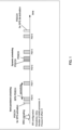
- FIG. 1 illustrates exemplary scheduling of Dynamic scheduling and SPS.
- parameters related to SPS configuration including a transmission period (periodicity), the number of HARQ processes (nrofHARQ-Processes), and an offset for a process number (harq-ProcID-Offset) may be indicated (or configured) to a terminal by RRC signaling (e.g., SPS-Config).
- SPS transmission may be activated, for example, by transmission of a PDCCH that indicates SPS activation.
- the base station may transmit data (e.g., PDSCH) using the specified frequency resource or MCS in the configured transmission period, for example.
- SPS transmission may be de-activated, for example, by transmission of a PDCCH that indicates SPS de-activation, and the periodic transmission may be stopped.
- CS-RNTI Configured Scheduling - Radio Network Temporary Identifier
- the HARQ process ID (PID) of PDSCH transmitted in SPS may be determined based on the transmission slot of the SPS PDSCH.
- the HARQ process ID of SPS PDSCH may be determined by the following equation (e.g., see NPL 2).
- HARQ Process ID [floor (CURRENT_slot ⁇ 10 / (numberOfSlotsPerFrame ⁇ periodicity))]modulo nrofHARQ-Process + harq-ProcID-Offset
- CURRENT_slot herein indicates a slot number in which the SPS PDSCH is transmitted
- numberOfSlotsPerFrame indicates the number of slots per frame
- periodicity indicates a transmission period
- nrofHARQ-Processes indicates the number of HARQ processes for SPS
- harq-ProcID-Offset indicates a process number offset.
- a plurality of SPS configurations may be configured for a terminal.
- dynamic scheduling may be performed even during a period in which SPS is activated.
- retransmission of SPS PDSCH may be performed by dynamic scheduling.
- CRC Cyclic Redundancy Check
- a PDCCH in which CRC part is scrambled by Cell-RNTI (C-RNTI) may be used for scheduling of new data different from the data transmitted by SPS or for scheduling of retransmission of the data.
- a PDSCH transmitted by dynamic scheduling is sometimes referred to as "Dynamic Grant PDSCH (DG PDSCH)," for example.
- DG PDSCH Dynamic Grant PDSCH
- NTN Non-Terrestrial Network
- LTE and NR Rel. 15/16 have been specified as radio access technologies for terrestrial networks. Meanwhile, extension of NR to non-terrestrial networks (NTN) such as communication using a satellite and/or a high-altitude platform station (HAPS) has been studied (e.g., see NPL 1).
- NTN non-terrestrial networks
- HAPS high-altitude platform station
- a coverage area e.g., one or more cells
- a coverage area e.g., one or more cells
- a beam from the satellite is formed by a beam from the satellite.
- a round trip time (RTT) of radio wave propagation between the terminal and the satellite is determined depending on the altitude of the satellite (e.g., approximately up to 36000 km) and the angle viewed from the terminal, that is, the positional relation between the satellite and the terminal.
- NPL 1 describes that the round trip time (RTT) of radio wave propagation between the base station and the terminal takes up to approximately 540 ms in the NTN.
- RTT round trip time
- Retransmission control is performed based on HARQ-ACK feedback (e.g., also referred to as HARQ feedback or UL HARQ feedback) configured for each HARQ process, for example.
- HARQ-ACK feedback e.g., also referred to as HARQ feedback or UL HARQ feedback
- HARQ feedback e.g., also referred to as HARQ feedback or UL HARQ feedback
- HARQ feedback e.g., also referred to as HARQ feedback or UL HARQ feedback
- a terminal may transmit a response signal (e.g., referred to as "HARQ-ACK" or "ACK/NACK”) and the base station may perform scheduling based on the HARQ-ACK.
- HARQ-ACK response signal
- ACK/NACK ACK/NACK
- a terminal transmits no HARQ-ACK and the base station may schedule next data without waiting for reception of HARQ-ACK.
- feedback enabling/disabling configuration may be performed for each HARQ process (e.g., per HARQ process).
- the base station may transmit retransmission data without receiving a HARQ-ACK.
- the terminal may hold reception data in a buffer and may perform HARQ combining even for a HARQ process in which feedback is disabled.
- the retransmission without receiving a HARQ-ACK is sometimes referred to as "Blind retransmission" or "Open loop HARQ.”
- a HARQ process ID is determined based on a transmission slot in SPS.
- feedback enabling/disabling configurations for transmission slots of SPS are possibly different from one another depending on the feedback enabling/disabling configuration per HARQ process.
- data of the same data traffic type may be transmitted in the same SPS configuration (SPS-Config).
- SPS-Config SPS configuration
- QoS Quality of Service
- feedback enabling/disabling configuration for each SPS configuration (SPS-Config) (per SPS configuration) may be performed.
- SPS-Config per SPS configuration
- Feedback enabling/disabling configurations for slots of SPS are made common by the feedback enabling /disabling configuration per SPS configuration, and thus the QoS of the data traffic is easily satisfied.
- a feedback enabling/disabling configuration per HARQ process and a feedback enabling/disabling configuration per SPS configuration are possibly different from each other for a certain HARQ process ID. There is room for further study on the operation in this case.
- a method for configuring enabling/disabling of feedback when a feedback enabling/disabling configuration per HARQ process and a feedback enabling/disabling configuration per SPS configuration are different from each other for a certain HARQ process ID.
- feedback enabling/disabling configuration per SPS configuration (e.g., SPS-Config) is performed.
- whether to follow a feedback enabling/disabling configuration per HARQ process or a feedback enabling/disabling configuration per SPS configuration may be determined, for a PDSCH (e.g., DG PDSCH) with the same process ID as HARQ process ID configured for SPS, based on at least one of a type of RNTI by which CRC part of a PDCCH used for scheduling a PDSCH is scrambled and/or a HARQ process ID.
- a communication system includes base station 100 and terminal 200.
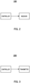
- FIG. 2 is a block diagram illustrating an exemplary configuration of a part of base station 100 (e.g., corresponding to a communication apparatus).
- a controller e.g., corresponding to control circuitry determines a configuration related to enabling and disabling of feedback (e.g., HARQ feedback) in retransmission control of dynamic scheduling based on a type of an identifier (e.g., RNTI) used for a control signal (e.g., PDCCH) performing dynamic scheduling.
- a receiver e.g., corresponding to reception circuitry
- receive processing on a feedback signal e.g., HARQ-ACK
- FIG. 3 is a block diagram illustrating an exemplary configuration of a part of terminal 200 (e.g., corresponding to a communication apparatus).
- a controller e.g., corresponding to control circuitry determines a configuration related to enabling and disabling of feedback (e.g., HARQ feedback) in retransmission control of dynamic scheduling based on a type of an identifier (e.g., RNTI) used for a control signal (e.g., PDCCH) performing dynamic scheduling.
- a transmitter e.g., corresponding to transmission circuitry
- a feedback signal e.g., HARQ-ACK
- FIG. 4 is a block diagram illustrating an exemplary configuration of base station 100 according to the present embodiment.
- Base station 100 includes, for example, controller 101, encoder/modulator 102, radio transmitter 103, antenna 104, radio receiver 105, demodulator/decoder 106, HARQ-ACK determiner 107, and retransmission controller 108.
- controller 101 At least one of controller 101, encoder/modulator 102, demodulator/decoder 106, HARQ-ACK determiner 107, and retransmission controller 108 illustrated in FIG. 4 may be included in the controller illustrated in FIG. 2 .
- At least one of antenna 104 and radio receiver 105 illustrated in FIG. 4 may be included in the transmitter illustrated in FIG. 2 , for example.
- Controller 101 may generate, for example, information on a feedback enabling/disabling configuration per HARQ process (e.g., HARQprocess-disableULfeedback). For example, controller 101 may generate information on a feedback-enabled HARQ process ID and a feedback-disabled HARQ process ID. For example, the information on a feedback enabling/disabling configuration per HARQ process may be included in a PDSCH-Config Information Element (IE).
- IE PDSCH-Config Information Element
- controller 101 may generate, for example, information on SPS configuration.
- the information on SPS configuration may include, for example, at least one of an SPS transmission period (periodicity), the number of HARQ processes (nrofHARQ-Processes), a process number offset (harq-ProcID-Offset), and a feedback enabling/disabling configuration (e.g., HARQfeedback).
- the information on SPS configuration may be included in SPS-Config IE, for example.
- At least one of the information on the feedback enabling/disabling configuration per HARQ process and the information on SPS configuration may be included in higher layer signaling (e.g., RRC reconfiguration message), or may be included in a control signal different from higher layer signaling (e.g., DCI).
- controller 101 may generate a plurality of pieces of information on SPS configuration for terminal 200. Furthermore, controller 101 may generate a plurality of pieces of information on feedback enabling/disabling configurations.
- Controller 101 outputs the generated control information to encoder/modulator 102.
- encoder/modulator 102 performs, on inputted transmission data (e.g., transport block) and the control information inputted from controller 101, error correction coding such as turbo coding, LDPC coding, or polar coding and modulation such as Quarter Phase Shift Keying (QPSK) or Quadrature Amplitude Modulation (QAM), and outputs the modulated signal to radio transmitter 103.
- error correction coding such as turbo coding, LDPC coding, or polar coding and modulation such as Quarter Phase Shift Keying (QPSK) or Quadrature Amplitude Modulation (QAM)
- QPSK Quarter Phase Shift Keying
- QAM Quadrature Amplitude Modulation
- Encoder/modulator 102 may, for example, store transmission data in a buffer.
- encoder/modulator 102 may perform the same processing as described above on the transmission data (e.g., retransmission data) stored in the buffer.
- retransmission controller 108 indicates no retransmission (or transmission of new data)
- encoder/modulator 102 may delete the corresponding transmission data stored in the buffer.
- encoder/modulator 102 encodes and modulates downlink control information (e.g., DCI) and outputs the modulated signal to radio transmitter 103.
- DCI may include, for example, data assignment information such as time and frequency resource allocation information and information on a coding and modulation scheme (e.g., MCS information).
- DCI may also include, for example, information indicating a HARQ process ID, an NDI, an RV, a HARQ-ACK transmission timing (e.g., PDSCH-to-HARQ_feedback timing indicator) or information on retransmission control inputted from retransmission controller 108, such as Downlink Assignment Index (DAI) (e.g., Counter-DAI(C-DAI), Total-DAI(T-DAI)).
- DAI Downlink Assignment Index
- radio transmitter 103 performs transmission processing such as D/A conversion, up-conversion, and amplification on the signal inputted from encoder/modulator 102, and transmits the radio signal after the transmission processing from antenna 104.
- transmission processing such as D/A conversion, up-conversion, and amplification
- the transmission data may herein correspond to a PDSCH, and the data assignment information may correspond to DCI or a PDCCH
- CRC part of PDCCH may be scrambled by an identifier (e.g., C-RNTI) individually assigned to terminal 200 in order for terminal 200 to identify the PDCCH addressed to terminal 200.
- C-RNTI an identifier
- base station 100 may generate DCI or a PDCCH that includes control information for activating or deactivating (or releasing) SPS transmission, for example. After activating SPS transmission, base station 100 may periodically perform data transmission processing in accordance with the SPS transmission period (periodicity). For example, control information (e.g., DCI) such as data assignment information need not be generated and transmitted for the SPS periodic transmission. Meanwhile, for retransmission data for data (PDSCH) transmitted by SPS, base station 100 may indicate the above-described assignment information to terminal 200 using a PDCCH in which CRC part is scrambled by an identifier (e.g., CS-RNTI) assigned to each terminal 200.
- a PDCCH in which CRC part is scrambled by an identifier (e.g., CS-RNTI) assigned to each terminal 200.
- Radio receiver 105 performs, for example, reception processing such as downconversion and A/D conversion on a data signal (e.g., Physical Uplink Shared Channel (PUSCH)) and a control signal (e.g., HARQ-ACK information) from terminal 200 received via antenna 104, and outputs the signal after the reception processing to demodulator/decoder 106.
- reception processing such as downconversion and A/D conversion on a data signal (e.g., Physical Uplink Shared Channel (PUSCH)) and a control signal (e.g., HARQ-ACK information) from terminal 200 received via antenna 104, and outputs the signal after the reception processing to demodulator/decoder 106.
- PUSCH Physical Uplink Shared Channel
- HARQ-ACK information e.g., HARQ-ACK information
- Demodulator/decoder 106 performs, for example, channel estimation, demodulation processing, and decoding processing on the received signal inputted from radio receiver 105.
- demodulator/decoder 106 When the received signal is data, demodulator/decoder 106 outputs the received data, and when the received signal is HARQ-ACK information, demodulator/decoder 106 outputs the HARQ-ACK information to HARQ-ACK determiner 107, for example.
- HARQ-ACK determiner 107 determines the presence or absence of an error (e.g., ACK or NACK) for each transmission data (e.g., transport block) that has been transmitted, based on the HARQ-ACK information inputted from demodulator/decoder 106. For example, when the HARQ-ACK information is NACK, HARQ-ACK determiner 107 may indicate retransmission of data to retransmission controller 108. Further, for example, when the HARQ-ACK information is ACK, HARQ-ACK determiner 107 may indicate non-retransmission of data to retransmission controller 108. Furthermore, for example, HARQ-ACK determiner 107 may determine that the HARQ-ACK information is NACK when no HARQ-ACK information is received from terminal 200.
- an error e.g., ACK or NACK
- Retransmission controller 108 controls retransmission of transmission data (e.g., PDSCH).
- retransmission controller 108 may generate information on retransmission control including at least one of a HARQ process ID, an NDI, an RV, information indicating a HARQ-ACK transmission timing (e.g., PDSCH-to-HARQ_feedback timinig indicator), and DAI (C-DAI, T-DAI) for transmission data.
- Retransmission controller 108 outputs the generated information on retransmission control to encoder/modulator 102.
- Retransmission controller 108 may, for example, determine retransmission of transmission data (or transmission of new data) based on the information inputted from HARQ-ACK determiner 107, and indicate whether transmission data to be retransmitted to encoder/modulator 102. For example, retransmission controller 108 indicates retransmission of data to encoder/modulator 102 when the information indicates NACK. Further, in case of a HARQ-feedback-disabled HARQ process, for example, retransmission controller 108 may indicate, to encoder/modulator 102, retransmission of data for the specified (or configured) number of times, regardless of HARQ-ACK information.
- terminal 200 Next, an exemplary configuration of terminal 200 will be described.
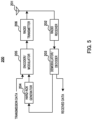
- FIG. 5 is a block diagram illustrating an exemplary configuration of terminal 200 according to the present embodiment.
- Terminal 200 includes, for example, antenna 201, radio receiver 202, demodulator/decoder 203, HARQ-ACK generator 204, encoder/modulator 205, and radio transmitter 206.
- demodulator/decoder 203 may be included in the controller illustrated in FIG. 3 .
- at least one of antenna 201 and radio transmitter 206 illustrated in FIG. 5 may be included in the transmitter illustrated in FIG. 3 , for example.
- Radio receiver 202 performs, for example, reception processing such as downconversion and A/D conversion on a data signal (e.g., PDSCH) and a control signal (e.g., PDCCH or DCI) from base station 100 received via antenna 201, and outputs the signal after the reception processing to demodulator/decoder 203.
- reception processing such as downconversion and A/D conversion on a data signal (e.g., PDSCH) and a control signal (e.g., PDCCH or DCI) from base station 100 received via antenna 201, and outputs the signal after the reception processing to demodulator/decoder 203.
- Demodulator/decoder 203 performs, for example, channel estimation, demodulation processing, and decoding processing on the received signal inputted from radio receiver 202.
- demodulator/decoder 203 may perform processing based on data assignment information (e.g., modulation scheme and coding rate) included in the control signal, for example.
- data assignment information e.g., modulation scheme and coding rate
- demodulator/decoder 203 may descramble the control signal (e.g., CRC part of PDCCH) using an identifier (e.g., RNTI such as C-RNTI or CS RNTI) assigned to terminal 200. Then, demodulator/decoder 203 identifies a modulation scheme and coding rate based on the data assignment information included in the detected control signal to perform processing.
- RNTI such as C-RNTI or CS RNTI
- demodulator/decoder 203 may determine whether the received data is initial transmission data or retransmission data, based on the NDI included in the control signal, for example. For example, when the received data is initial transmission data, demodulator/decoder 203 may perform error correction decoding and CRC determination. For example, when the received data is retransmission data, demodulator/decoder 203 may perform error correction decoding after combining the data stored in a buffer (past received data) with the received data, and perform CRC determination. Demodulator/decoder 203 outputs the CRC determination result to HARQ-ACK generator 204, for example.
- HARQ-ACK generator 204 generates HARQ-ACK information (e.g., HARQ-ACK codebook) based on the CRC determination result inputted from demodulator/decoder 203 and outputs the generated information to encoder/modulator 205, for example.
- HARQ-ACK information e.g., HARQ-ACK codebook
- HARQ-ACK generator 204 may generate HARQ-ACK information based on a feedback enabling/disabling configuration. Note that the determination of the feedback enabling/disabling configuration will be described later.
- HARQ-ACK generator 204 generates HARQ-ACK information (e.g., ACK or NACK) based on the CRC determination result for data to which enabling of feedback is configured. For example, HARQ-ACK generator 204 generates an ACK in case of CRC OK (e.g., no error) and generates a NACK in case of CRC NG (Not Good, e.g., with error). Further, for example, when terminal 200 receives a plurality of transport blocks or code blocks, HARQ-ACK generator 204 may generate a HARQ-ACK for each of the plurality of transport blocks or code blocks or generate a HARQ-ACK code block composed of a plurality of HARQ-ACKs.
- CRC OK e.g., no error
- CRC NG Not Good, e.g., with error
- HARQ-ACK generator 204 may generate no HARQ-ACK information for feedback-disabled data (or data in feedback-disabled HARQ process). Note that terminal 200 need not transmit HARQ-ACK information generated for the feedback-disabled data.
- Encoder/modulator 205 performs, for example, error correction coding and modulation processing on inputted transmission data (e.g., transport block), and outputs the modulated signal to radio transmitter 206. Encoder/modulator 205 also performs, for example, error correction coding and modulation processing on the HARQ-ACK information inputted from HARQ-ACK generator 204, for example, and outputs the modulated signal to radio transmitter 206.
- error correction coding and modulation processing on inputted transmission data (e.g., transport block), and outputs the modulated signal to radio transmitter 206.
- radio transmitter 206 performs transmission processing such as D/A conversion, up-conversion, and amplification on the signal inputted from encoder/modulator 205, and transmits the radio signal after the transmission processing from antenna 201.
- Terminal 200 may transmit the HARQ-ACK information at a timing based on the PDSCH-to-HARQ_feedback timing indicator included in the control signal from base station 100, for example.
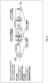
- FIG. 6 is a sequence diagram illustrating exemplary operations of base station 100 and terminal 200 in the present embodiment.
- base station 100 determines a HARQ feedback configuration for terminal 200, for example (S101).
- the HARQ feedback configuration may include a feedback enabling/disabling configuration per HARQ process and a feedback enabling/disabling configuration per SPS configuration (e.g., SPS config), for example.
- Base station 100 transmits control information to terminal 200, for example (S102).
- the control information may include information on the HARQ feedback configuration or data assignment information. Note that these pieces of information may be collectively transmitted to terminal 200 by at least one of RRC signaling, MAC Control Element (MAC CE), and a PDCCH, or may be transmitted to terminal 200 at different timings.
- MAC CE MAC Control Element
- PDCCH Physical Downlink Control Channel
- Terminal 200 identifies the HARQ feedback configuration based on the control information (S103).
- Base station 100 transmits downlink data to terminal 200, for example (S104).
- Terminal 200 receives the downlink data based on, for example, the data assignment information included in the control information (S105).
- Terminal 200 performs transmission processing on HARQ-ACK information for the downlink data based on the HARQ feedback configuration included in the control information, for example (S106). For example, terminal 200 may determine whether to transmit HARQ-ACK information.
- terminal 200 when HARQ feedback is enabled, terminal 200 transmits HARQ-ACK information to base station 100, and when HARQ feedback is disabled, terminal 200 stops transmission of HARQ-ACK information (S107).
- Base station 100 performs retransmission control of downlink data for terminal 200 (S108). For example, base station 100 may perform retransmission control based on the HARQ-ACK information from terminal 200, or may perform retransmission control regardless of the HARQ-ACK information from terminal 200.
- Base station 100 may indicate, to terminal 200, information on a feedback enabling/disabling configuration per HARQ process ID (e.g., HARQprocess-disableULfeedback) by RRC signaling (e.g., RRC reconfiguration message).
- RRC signaling e.g., RRC reconfiguration message
- base station 100 may indicate, to terminal 200, information on SPS configuration (e.g., SPS-Config) corresponding to a request condition or characteristic of QoS of communication traffic with each terminal 200, for example.
- SPS configuration e.g., SPS-Config
- base station 100 may indicate the information on SPS configuration to terminal 200 that uses an application periodically generating the same amount of data, such as a voice call or a video transmission.
- the information on SPS configuration may include, for example, an SPS transmission period (periodicity), the number of HARQ processes (nrofHARQ-Processes), a process number offset (harq-ProcID-Offset), and a feedback enabling/disabling configuration for SPS transmission (e.g., HARQfeedback).
- base station 100 may indicate a plurality (a plurality of sets) of SPS configurations to terminal 200.
- FIG.7 illustrates an exemplary feedback configuration when a single SPS configuration is indicated to terminal 200.
- the number of HARQ processes is set to 4
- the HARQ process ID offset is set to 0
- the feedback enabling/disabling configuration is set to "enable.”
- a PID in case of transmission different from SPS transmission is indicated to terminal 200 by, for example, a PDCCH corresponding to (or associated with) each PDSCH.
- HARQ-Config a configuration based on the feedback enabling/disabling configuration (e.g., HARQfeedback) for SPS transmission in the SPS configuration (SPS-Config) is applied.
- HARQ-ACK information ACK or NACK
- terminal 200 may determine HARQ feedback of dynamic scheduling based on the type of RNTI used for a PDCCH scheduling a PDSCH (e.g., DG PDSCH) (e.g., RNTI used for scrambling CRC part). For example, when C-RNTI is used, a set value in accordance with the feedback enabling/disabling configuration per HARQ process (or HARQ process ID) (HARQprocess-disableULfeedback) may be applied. Further, for example, when CS-RNTI is used, a set value in accordance with the feedback enabling/disabling configuration (HARQfeedback) per SPS configuration may be applied.
- HARQfeedback a set value in accordance with the feedback enabling/disabling configuration per SPS configuration
- base station 100 and terminal 200 may configure disabling of feedback in accordance with the feedback enabling/disabling configuration per HARQ process ID (HARQprocess-disableULfeedback). In this case, terminal 200 need not transmit HARQ-ACK information for the PDSCH. Further, base station 100 may, for example, perform retransmission control, assuming that HARQ-ACK information for the PDSCH is not transmitted.
- base station 100 and terminal 200 may configure enabling of HARQ feedback in accordance with the feedback enabling/disabling configuration (HARQfeedback) per SPS configuration.
- terminal 200 may transmit HARQ-ACK information for the PDSCH.
- base station 100 may, for example, receive HARQ-ACK information for the PDSCH and perform retransmission control based on the received HARQ-ACK information.
- base station 100 and terminal 200 may configure HARQ feedback in accordance with the feedback enabling/disabling configuration per HARQ process ID.
- base station 100 and terminal 200 may configure HARQ feedback in accordance with the feedback enabling/disabling configuration per SPS configuration.
- terminal 200 may determine that the PDCCH is disabled and may discard the PDCCH.
- base station 100 and terminal 200 may determine a feedback enabling/disabling configuration for a PDSCH scheduled by dynamic scheduling (e.g., DG PDSCH), based on the type of RNTI used for a PDCCH performing dynamic scheduling. For example, when the type of RNTI is CS-RNTI, base station 100 and terminal 200 may determine a feedback enabling/disabling configuration configured per SPS configuration as the feedback enabling/disabling configuration for the DG PDSCH. Further, for example, when the type of RNTI is C-RNTI, base station 100 and terminal 200 may determine a feedback enabling/disabling configuration configured per HARQ process as the feedback enabling/disabling configuration for the DG PDSCH.
- DG PDSCH dynamic scheduling
- CS-RNTI is used for scrambling a PDCCH that schedules a PDSCH used for retransmission of data that is SPS-transmitted.
- terminal 200 can apply the same feedback enabling/disabling configuration to both initial transmission and retransmission for SPS data transmission. For example, in FIG.
- enabling of HARQ feedback is configured for an SPS PDSCH (e.g., periodic transmissions by SPS) and enabling of HARQ feedback is configured for a DG PDSCH used for SPS retransmission.
- SPS PDSCH e.g., periodic transmissions by SPS
- enabling of HARQ feedback is configured for a DG PDSCH used for SPS retransmission.
- the same HARQ feedback configuration (enable or disable) as configured for SPS periodic transmission is applied to retransmission of SPS data, which allows SPS data transmission that satisfies QoS requirement.
- C-RNTI is used for scrambling a PDCCH that schedules a PDSCH used for transmission (or retransmission) of data different from data that is SPS-transmitted.
- terminal 200 can perform, regardless of SPS configuration, communication by a feedback enabling/disabling configuration that depends on the characteristic of the traffic using dynamic scheduling.
- the HARQ feedback configuration for dynamic scheduling varies (or is changed) in a period before or after SPS configuration is indicated to terminal 200. Therefore, it is possible to avoid inconsistencies in recognition between base station 100 and terminal 200, and to realize simple operations in base station 100 and terminal 200.
- FIG. 8 illustrates an exemplary feedback configuration when a plurality of SPS configurations is indicated to terminal 200.
- SPS-Config1 and SPS-Config2 are configured for terminal 200.
- the SPS configurations may be identified, for example, by an SPS configuration index (e.g., sps-ConfigIndex).
- the number of HARQ processes is set to 2
- the HARQ process ID offset (harq-ProcID-Offset)
- the feedback enabling/disabling configuration (HARQfeedback) for SPS is set to "enable.”
- the number of HARQ processes is set to 2
- the HARQ process ID offset (harq-ProcID-Offset)
- the feedback enabling/disabling configuration (HARQfeedback) for SPS is set to "disable.”
- a configuration based on the feedback enabling/disabling configuration for SPS transmission e.g., HARQfeedback
- SPS-Config1 and SPS-Config2 a configuration based on the feedback enabling/disabling configuration for SPS transmission (e.g., HARQfeedback) in each of SPS configurations (e.g., SPS-Config1 and SPS-Config2) is applied.
- HARQ-ACK information ACK or NACK
- terminal 200 transmits no HARQfeedcabk information after receiving each SPS PDSCH.
- terminal 200 may determine the HARQ feedback configuration of dynamic scheduling based on the type of RNTI used for a PDCCH scheduling a PDSCH (e.g., DG PDSCH) (e.g., RNTI used for scrambling CRC part).
- a PDSCH e.g., DG PDSCH
- RNTI used for scrambling CRC part
- HARQprocess-disableULfeedback when C-RNTI is used, a set value in accordance with the feedback enabling/disabling configuration per HARQ process (or HARQ process ID) may be applied (HARQprocess-disableULfeedback).
- a set value in accordance with the feedback enabling/disabling configuration for SPS transmission (HARQfeedback) corresponding to the SPS configuration (or SPS configuration index) in which the HARQ process ID (PID) indicated by a PDCCH is configured may be applied.
- terminal 200 may determine, among respective feedback enabling/disabling configurations for a plurality of SPS configurations, the feedback enabling/disabling configuration in the SPS configuration corresponding to the HARQ process ID used for dynamic scheduling as the feedback enabling/disabling configuration in the dynamic scheduling.
- terminal 200 may transmit HARQ-ACK information for the PDSCH.
- base station 100 may, for example, receive HARQ-ACK information for the PDSCH and perform retransmission control based on the received HARQ-ACK information.
- base station 100 may indicate PDSCH allocation for retransmission to a feedback-disabled SPS PDSCH (SPS PDSCH for which corresponding HARQ-ACK information is not transmitted) by a PDCCH for which CS-RNTI is used. This can realize blind retransmission, in which retransmission data is transmitted for SPS data transmission without HARQ feedback.
- base station 100 and terminal 200 may determine a feedback enabling/disabling configuration for a PDSCH (e.g., DG PDSCH) scheduled by dynamic scheduling, based on the type of RNTI used for a PDCCH performing dynamic scheduling. Further, when a plurality of SPS configurations is configured for terminal 200, base station 100 and terminal 200 may determine a feedback enabling/disabling configuration for an SPS PDSCH scheduled by a PDCCH based on the feedback enabling/disabling configuration for the SPS configuration corresponding to the HARQ process ID indicated by the PDCCH.
- a PDSCH e.g., DG PDSCH
- base station 100 and terminal 200 may determine a feedback enabling/disabling configuration for an SPS PDSCH scheduled by a PDCCH based on the feedback enabling/disabling configuration for the SPS configuration corresponding to the HARQ process ID indicated by the PDCCH.
- the same feedback enabling/disabling configuration can be applied to both initial transmission and retransmission for data transmission for SPS of the same SPS configuration index.
- the same HARQ feedback configuration (enable or disable) as configured for SPS periodic transmission is applied to retransmission of SPS data, which allows SPS data transmission that satisfies QoS requirement.
- the feedback enabling/disabling configuration (or interpretation) for a PDSCH scheduled by a PDCCH scrambled by C-RNTI is the same as that in the case where there is a single SPS configuration as described in Operation Example 1.
- the feedback enabling/disabling configuration per HARQ process regardless of SPS configuration when C-RNTI is used for a PDCCH that schedules a PDSCH, it can be avoided that the HARQ feedback configuration for dynamic scheduling varies in a period before or after SPS configuration is indicated to terminal 200. Therefore, it is possible to avoid inconsistencies in recognition between base station 100 and terminal 200, and to realize simple operations in base station 100 and terminal 200.
- base station 100 and terminal 200 The exemplary operation of base station 100 and terminal 200 has been described above.
- base station 100 and terminal 200 determine a configuration related to enabling and disabling of HARQ feedback of dynamic scheduling based on the type of RNTI used for a PDCCH performing dynamic scheduling. Then, terminal 200 performs transmission processing (e.g., determination of transmission and non-transmission) on HARQ-ACK information based on the determined configuration of enabling and disabling of HARQ feedback, and base station 100 performs reception processing (e.g., determination of reception and non-reception) on the HARQ-ACK information based on the determined configuration of enabling and disabling of HARQ feedback.
- transmission processing e.g., determination of transmission and non-transmission
- base station 100 performs reception processing (e.g., determination of reception and non-reception) on the HARQ-ACK information based on the determined configuration of enabling and disabling of HARQ feedback.
- base station 100 and terminal 200 can appropriately determine the feedback enabling/disabling configuration even when the feedback enabling/disabling configuration per HARQ process for a certain HARQ process ID and the feedback enabling/disabling configuration per SPS configuration is different from each other. Therefore, according to the present embodiment, it is possible to improve the efficiency of retransmission control by HARQ.
- configurations of the base station and the terminal may be the same as those of base station 100 and terminal 200 in Embodiment 1.
- the operation when the type of RNTI used for scrambling CRC part of PDCCH used for scheduling PDSCH is CS-RNTI may be the same as that in Embodiment 1.
- the operation related to the feedback enabling/disabling configuration (or interpretation) when the type of RNTI used for scrambling CRC part of PDCCH used for scheduling PDSCH is C-RNTI is different from that in Embodiment 1.
- base station 100 and terminal 200 may determine a feedback enabling/disabling configuration based on a HARQ process ID indicated to terminal 200 by the PDCCH (in other words, HARQ process ID used for dynamic scheduling). For example, base station 100 and terminal 200 may determine a feedback enabling/disabling configuration depending on whether the HARQ process ID used for dynamic scheduling is a HARQ process ID used for SPS transmission.
- enabling/disabling of feedback is configured to a PDSCH scheduled by a PDCCH scrambled by C-RNTI, depending on a HARQ process ID indicated by the PDCCH (or HARQ process ID configured to the PDSCH).
- a HARQ process ID indicated by the PDCCH is a HARQ process ID that is not used for SPS transmission
- terminal 200 may apply the feedback enabling/disabling configuration per HARQ process.
- terminal 200 may apply the feedback enabling/disabling configuration of the SPS configuration.
- FIG. 9 illustrates an exemplary feedback configuration
- the number of HARQ processes is set to 4
- the HARQ process ID offset is set to 0
- the feedback enabling/disabling configuration is set to "enable.”
- the same feedback enabling/disabling configuration is applied to the same HARQ process regardless of whether the scheduling is dynamic scheduling or SPS.
- the HARQ process ID may be herein used as a unit of buffer management in HARQ.
- buffer management is likely to be complicated when different feedback configurations are applied to the same HARQ process ID.
- the same feedback configuration is applied to both SPS transmission and transmission by dynamic scheduling corresponding to the same HARQ process ID, which can simplify buffer management of HARQ in terminal 200 and base station 100.
- the feedback enabling/disabling configuration of SPS configuration may be applied in a period where SPS is activated, and the feedback enabling/disabling configuration per HARQ process may be applied in a period different from the period where SPS is activated (e.g., period where SPS is deactivated).
- a HARQ feedback configuration suitable for dynamic scheduling can be used by applying the HARQ feedback configuration per HARQ process.
- configurations of the base station and the terminal may be the same as those of base station 100 and terminal 200 in Embodiment 1.
- other operations including HARQ feedback configurations for PSDCHs scheduled by PDCCHs scrambled by C-RNTI and CS-RNTI may be operations based on at least one of Embodiments 1 and 2, for example.
- Embodiments 1 and 2 cases has been described in which the feedback enabling/disabling configuration per SPS configuration (e.g., HARQfeedback) is explicitly indicated to terminal 200.
- the feedback enabling/disabling configuration per SPS configuration may be implicitly indicated to terminal 200.
- the feedback enabling/disabling configuration per SPS configuration may be determined based on, for example, one HARQ process ID (e.g., referred to as a particular HARQ process ID) among HARQ process IDs used for SPS configuration (SPS-Config).
- the feedback enabling/disabling configuration per SPS configuration may be determined based on a set value corresponding to the above-described particular HARQ process ID in the feedback enabling/disabling configuration per HARQ process ID.
- the particular HARQ process ID may be herein the minimum HARQ process ID, the maximum process ID, or a separately specified HARQ process ID, among HARQ process IDs included in SPS configuration, for example.
- FIG. 10 illustrates an exemplary feedback configuration.
- the minimum HARQ process ID among HARQ process IDs in SPS configuration is the particular HARQ process ID.
- two SPS configurations are exemplarily configured.
- SPS-config1 the number of HARQ processes is set to 4 and the HARQ process ID offset is set to 0.
- SPS-Config2 the number of HARQ processes is set to 2 and the HARQ process ID offset is set to 4.
- terminal 200 determines the HARQ feedback configuration of SPS configuration based on the HARQ feedback configuration per HARQ process and the particular HARQ process ID in the SPS configuration.
- base station 100 can indicate or configure the HARQ feedback configuration per SPS configuration to terminal 200 without adding a parameter for HARQ feedback in SPS configuration, which reduces overhead of indication.
- configurations of the base station and the terminal may be the same as those of base station 100 and terminal 200 in Embodiment 1.
- the usage of the PDCCH scrambled by CS-RNTI is different from that in Embodiments 1 to 3.
- the operations related to the HARQ feedback configuration per HARQ process, the HARQ feedback configuration per SPS configuration, and the HARQ feedback configuration for a PDSCH scheduled by a PDCCH scrambled by C-RNTI may be operations based on at least one of Embodiments 1 to 3.
- base station 100 and terminal 200 need not perform retransmission processing for an SPS PDSCH for which disabling of HARQ feedback is configured.
- base station 100 need not perform transmission processing on retransmission data in SPS when disabling of feedback is configured in the feedback enabling/disabling configuration per SPS configuration.
- terminal 200 need not perform reception processing on retransmission data in SPS when disabling of feedback is configured in the feedback enabling/disabling configuration per SPS configuration.
- a PDCCH scrambled by CS-RNTI may be used for scheduling retransmission of an SPS PDSCH for which enabling of feedback is configured and need not used for an SPS PDSCH for which disabling of feedback is configured.
- enabling of feedback may be configured to a PDSCH scheduled by a PDCCH scrambled by CS-RNTI, and disabling of feedback need not be configured to the PDSCH.
- enabling of HARQ feedback may be, for example, always configured to a PDSCH scheduled by a PDCCH scrambled by CS-RNTI, which can simplify the operations of terminal 200 and base station 100.
- repetitive transmission e.g., Repetition or PDSCH Aggregation
- repetitive transmission may be configured for the SPS PDSCH.
- Repetitive transmission of the SPS PDSCH allows a plurality of transmissions of the SPS PDSCH, thereby suppressing deterioration of property such as reliability of SPS PDSCH caused by not performing a retransmission process.
- the configuration of repetitive transmission may be pre-configured in terminal 200 by RRC signaling, or may be indicated to terminal 200 by a PDCCH or DCI.
- Example 1 For an SPS configuration in which HARQ feedback is disabled, a terminal does not expect (or assume) to receive a retransmission of a PDSCH associated with the SPS configuration.
- Examples 4 and 5 are also applicable when the feedback enabling/disabling configuration per SPS configuration is not performed.
- Embodiments 1, 2, 3, and 4 may be used in combination.
- a feedback enabling/disabling configuration is determined based on Embodiment 1 for a PDSCH scheduled by a PDCCH scrambled by CS-RNTI
- a feedback enabling/disabling configuration is determined based on Embodiment 2 for a PDSCH scheduled by a PDCCH scrambled by C-RNTI.
- the feedback enabling/disabling configuration per SPS configuration may be configured (implicitly indicated) based on the feedback enabling/disabling configuration per HARQ process, based on Embodiment 3.
- transmission processing on retransmission data in SPS need not be performed when disabling of feedback is configured in the feedback enabling/disabling configuration per SPS configuration, based on Embodiment 4.
- an exemplary embodiment of the present disclosure is also applicable to any type of satellite, such as GEOs, medium orbit satellites (Medium Earth Orbit (MEO) satellites), LEOs, or high orbit satellites (Highly Elliptical Orbit (HEO) satellites). Further, an exemplary embodiment of the present disclosure may be applied to non-terrestrial communications such as a HAPS or a drone base station.
- GEOs Globalstar Satellite System
- MEO Medium Earth Orbit
- LEO Low Earth Orbit
- HEO High orbit satellites
- HEO Highly Elliptical Orbit
- an NTN environment e.g., satellite communication environment
- the present disclosure may be applied to other communication environments (e.g., terrestrial cellular environment of at least one of LTE and NR).
- an embodiment of the present disclosure may be applied to terrestrial communications in an environment where a cell size is large and a propagation delay between base station 100 and terminal 200 is longer (e.g., equal to or longer than a threshold), for example.
- an embodiment of the present disclosure may be applied not only to the NTN but also to communications to which HARQ or feedback-disabled HARQ is applied.
- a slot length transmission time unit
- an RTT including processing delays
- the feedback enabling/disabling configuration is assumed to be applied, and an embodiment of the present disclosure is applicable in such a case.
- a form of satellite communications may be configured so that the function of a base station is present in the satellite (e.g., "regenerative satellite"), or may be configured so that the function of a base station is present on the ground and the satellite relays communications between the base station and terminals (e.g., "transparent satellite”).
- downlink and uplink may be links between a terminal and a satellite or links through a satellite.
- disabling of HARQ feedback may be, for example, disabling of HARQ feedback or ACK/NACK feedback, and need not disable HARQ combining.
- base station 100 may perform retransmission without HARQ feedback, and terminal 200 may perform HARQ combining.
- terminal 200 may feed back ACK/NACK information when collectively feeding back ACK/NACK information for a plurality of data (e.g., PDSCHs) (e.g., HARQ feedback using type 1 HARQ-ACK codebook), even though disabling of HARQ feedback is configured.
- a plurality of data e.g., PDSCHs
- HARQ feedback using type 1 HARQ-ACK codebook e.g., HARQ feedback using type 1 HARQ-ACK codebook
- disabling of HARQ feedback may be, for example, disabling of retransmission control by HARQ (e.g., disabling of HARQ). In this case, both HARQ feedback and retransmission (or HARQ combining) need not be performed.
- the feedback enabling/disabling configuration per HARQ process may be configured by an RRC parameter "HARQprocess-disableULfeedback," or may be configured by another parameter. Further, the feedback enabling/disabling configuration per HARQ process may be a HARQ feedback configuration configured by a parameter different from that of a HARQ feedback configuration configured in SPS configuration (SPS-Config).
- a set value for enabling/disabling of feedback may be configured for each HARQ process ID and indicated to terminal 200, or either or both of information on HARQ process ID for which disabling of feedback is configured and information on HARQ process ID for which enabling of feedback is configured may be indicated to terminal 200.
- the information on the feedback enabling/disabling configuration per HARQ process or the information on SPS configuration may be individually configured to, for example, Component Carriers (or cells) or Bandwidth Parts (BWPs) whose carrier frequencies are different from one another. This allows an operation with an appropriate feedback configuration for each Component Carrier or BWP.
- Component Carriers or cells
- BWPs Bandwidth Parts
- base station 100 may generate control information such as a PUCCH resource used for HARQ feedback and indicate the control information to terminal 200.
- CG Configured grant
- SPS configuration can be read as Configured grant configuration.
- ConfiguredGrantConfig an RRC parameter "ConfiguredGrantConfig.”
- a retransmission subj ect is not limited to data (or data channel) and may be another signal or channel.
- a HARQ-ACK is not limited to a HARQ-ACK for reception of PDSCH, and may be a HARQ-ACK for another signal.
- feedback of the response signal (e.g., HARQ-ACK) to data has been described, but the feedback subject is not limited to HARQ-ACK, and may be another signal (e.g., another Uplink Control Information (UCI)).
- UCI Uplink Control Information
- enabling or disabling of HARQ feedback may be individually configured for terminals or individually configured for cells.
- the type of RNTI is not limited to C-RNTI and CS-RNTI, and may be RNTI of another type defined in the standard or RNTI of a type newly defined in a future standard.
- the identifier assigned to terminal 200 is not limited to RNTI, and may be another identifier.
- the feedback enabling/disabling configuration configured per HARQ process number is not limited to be configured as enable or disable to each set of consecutive PIDs as in FIGS. 7 , 8 , 9 , and 10 , and enabling or disabling may be configured to a set of non-consecutive PIDs.
- the type of RNTI used for determining the type of PDSCH scheduled by dynamic scheduling e.g., whether to be SPS PDSCH
- the type of RNTI used for determining a feedback enabling/disabling configuration are the same (e.g., either CS-RNTI or C-RNTI), but the present disclosure is not limited thereto.
- the type of RNTI used for determining the feedback enabling/disabling configuration may be different from the type of RNTI used for determining the type of PDSCH scheduled by dynamic scheduling.
- a method has been described by which a feedback enabling/disabling configuration is determined based on the type of RNTI used for PDCCH scrambling, but the determination of the feedback enabling/disabling need not depend on the type of RNTI and may be based on a HARQ process ID, for example.
- a HARQ process ID indicated by a PDCCH scheduling a PDSCH is a HARQ process ID used in at least one SPS configuration configured for terminal 200
- terminal 200 may apply the feedback enabling/disabling configuration of the corresponding SPS configuration to the PDSCH.
- terminal 200 may apply the feedback enabling/disabling configuration per HARQ process ID to the PDSCH.
- HARQ process ID e.g., the total number of processes or the number of processes used in each configuration
- number of SPS-Config e.g., the number of SPS-Config
- transmission cycle of SPS e.g., the transmission cycle of SPS
- offset value of HARQ process ID e.g., the offset value used in the present embodiments, is merely examples, and may be other values.
- RRC signaling (or RRC parameter) used in the above embodiments is not limited to that term, and may be another term.
- HARQ-ACK may be referred to as a ACK/NACK or HARQ-feedback, for example.
- SPS may be referred to as Configured scheduling, Configured grant, or Grant free, for example.
- HARQ process ID may be referred to as, for example, a HARQ process number (or index).
- the time resource (e.g., slot or symbol) in which a PDCCH or DCI is transmitted may be referred to as a PDCCH monitoring occasion. Further, the time resource (e.g., slot or symbol) in which a PDSCH is transmitted may be referred to as a PDSCH transmission occasion.
- Abase station may be referred to as a gNodeB or a gNB. Further, a terminal may be referred to as UE.
- a Slot may be replaced with a time slot, a mini-slot, a frame, a subframe, or the like.
- any component termed with a suffix, such as "-er,” “-or,” or “-ar” in the above-described embodiments may be replaced with other terms such as “circuit (circuitry),” “device,” “unit,” or “module.”
- Information indicating whether terminal 200 supports the functions, operations, or processing described in each of the above embodiments and variations may be transmitted (or indicated) from terminal 200 to base station 100 as, for example, capability information or a capability parameter of terminal 200.
- the capability information may include information elements (IEs) individually indicating whether terminal 200 supports at least one of the functions, operations, and processing described in each of the above embodiments and variations.
- the capability information may include an information element indicating whether terminal 200 supports a combination of any two or more of the functions, operations, and processing described in each of the above embodiments and variations.
- Base station 100 may determine (or assume) the function, operation, or process supported (or not supported) by terminal 200 of the transmission source of the capability information, based on the capability information received from terminal 200, for example. Base station 100 may perform an operation, processing, or control corresponding to the determination result based on the capability information. For example, base station 100 may control retransmission based on the capability information received from terminal 200.
- terminal 200 does not support some of the functions, operations, or processing described in each of the above embodiments and variations may be interpreted as limitation of such functions, operations, or processing in terminal 200. For example, information or a request on such limitation may be indicated to base station 100.
- Information on the capability or limitation of terminal 200 may be defined, for example, in the standard, or may be implicitly indicated to base station 100 in association with information known to base station 100 or information transmitted to base station 100.
- the downlink control signal (or downlink control information) may be a signal (or information) transmitted in a Physical Downlink Control Channel (PDCCH) in a physical layer, for example, or may be a signal (or information) transmitted in a Medium Access Control Control Element (MAC CE) or a Radio Resource Control (RRC) in a higher layer.
- the signal (or information) is not limited to that notified by the downlink control signal, but may be predefined in the specifications (or standard) or may be pre-configured for the base station and the terminal.
- the uplink control signal (or uplink control information) may be, for example, a signal (or information) transmitted in a PUCCH of the physical layer or a signal (or information) transmitted in the MAC CE or RRC of the higher layer. Further, the signal (or information) is not limited to that notified by the uplink control signal, and may be predefined in the specifications (or standard) or may be pre-configured for the base station and the terminal.
- the uplink control signal may be replaced with, for example, uplink control information (UCI), 1st stage sidelink control information (SCI), or 2nd stage SCI.
- UCI uplink control information
- SCI 1st stage sidelink control information
- 2nd stage SCI 2nd stage SCI.
- the base station may be a transmission reception point (TRP), a clusterhead, an access point, a remote radio head (RRH), an eNodeB (eNB), a gNodeB (gNB), a base station (BS), a base transceiver station (BTS), a base unit, or a gateway, for example.
- TRP transmission reception point
- RRH remote radio head
- eNB eNodeB
- gNodeB gNodeB
- BS base station
- BTS base transceiver station
- a gateway for example.
- a terminal may play a role of a base station.
- a relay apparatus that relays communication between a higher node and a terminal may be used.
- a road side device may be used.
- An exemplary embodiment of the present disclosure may be applied to, for example, any of an uplink, a downlink, and a sidelink.
- an exemplary embodiment of the present disclosure may be applied to a Physical Uplink Shared Channel (PUSCH), a Physical Uplink Control Channel (PUCCH), and a Physical Random Access Channel (PRACH) in the uplink, a Physical Downlink Shared Channel (PDSCH), PDCCH or a Physical Broadcast Channel (PBCH) in the downlink, or a Physical Sidelink Shared Channel (PSSCH), a Physical Sidelink Control Channel (PSCCH), a Physical Sidelink Broadcast Channel (PSBCH) in the sidelink.
- PUSCH Physical Uplink Shared Channel
- PUCCH Physical Uplink Control Channel
- PRACH Physical Random Access Channel
- PDSCH Physical Downlink Shared Channel
- PBCH Physical Broadcast Channel
- PSSCH Physical Sidelink Shared Channel
- PSCCH Physical Sidelink Control Channel
- PSBCH Physical Sidelink Broadcast Channel
- the PDCCH, PDSCH, PUSCH and PUCCH are examples of a downlink control channel, a downlink data channel, an uplink data channel, and an uplink control channel, respectively.
- the PSCCH and PSSCH are examples of a sidelink control channel and a sidelink data channel, respectively.
- the PBCH and PSBCH are examples of broadcast channels, and the PRACH is an exemplary random access channel.
- An exemplary embodiment of the present disclosure may be applied to, for example, either of a data channel or a control channel.
- a channel in an exemplary embodiment of the present disclosure may be replaced with any one of the PDSCH, PUSCH, and PSSCH being the data channels or the PDCCH, PUCCH, PBCH, PSCCH, and PSBCH being the control channels.
- a reference signal is a signal known to both of a base station and a mobile station, for example, and may also be referred to as a Reference Signal (RS) or a pilot signal.
- the reference signal may be any of a Demodulation Reference Signal (DMRS), a Channel State Information-Reference Signal (CSI-RS), a Tracking Reference Signal (TRS), a Phase Tracking Reference Signal (PTRS), a Cell-specific Reference Signal (CRS), or a Sounding Reference Signal (SRS).
- DMRS Demodulation Reference Signal
- CSI-RS Channel State Information-Reference Signal
- TRS Tracking Reference Signal
- PTRS Phase Tracking Reference Signal
- CRS Cell-specific Reference Signal
- SRS Sounding Reference Signal
- the units of time resources are not limited to one or a combination of slots and symbols, but may be time resource units such as, for example, frames, superframes, subframes, slots, time slot subslots, minislots, or symbols, Orthogonal Frequency Division Multiplexing (OFDM) symbols, Single Carrier-Frequency Division Multiplexing (SC-FDMA) symbols, or other time resource units.
- OFDM Orthogonal Frequency Division Multiplexing
- SC-FDMA Single Carrier-Frequency Division Multiplexing
- the number of symbols included in one slot is not limited to the number of symbols exemplified in the above-described embodiments, and may be another number of symbols.
- An exemplary embodiment of the present disclosure may be applied to either a licensed band or an unlicensed band (unlicensed spectrum, shared spectrum).
- a channel access procedure (Listen Before Talk (LBT), carrier sense, and/or Channel Clear Assessment (CCA)) may be performed prior to transmission of each signal.
- LBT Listen Before Talk
- CCA Channel Clear Assessment
- An exemplary embodiment of the present disclosure may be applied to any of communication between a base station and a terminal (Uu link communication), communication between a terminal and a terminal (Sidelink communication), and communication of a Vehicle to Everything (V2X).
- the channel in an exemplary embodiment of the present disclosure may be replaced with the PSCCH, PSSCH, Physical Sidelink Feedback Channel (PSFCH), PSBCH, PDCCH, PUCCH, PDSCH, PUSCH, or PBCH.
- an exemplary embodiment of the present disclosure may be applied to either of a terrestrial network or a network other than the terrestrial network using a satellite or a High Altitude Pseudo Satellite (HAPS) (Non-Terrestrial Network (NTN)). Further, an exemplary embodiment of the present disclosure may be applied to a terrestrial network having a larger transmission delay in comparison to a symbol length or a slot length, such as a network having a large cell size or an ultra-wideband transmission network.
- HAPS High Altitude Pseudo Satellite
- NTN Non-Terrestrial Network
- an antenna port refers to a logical antenna (antenna group) composed of one physical antennas or a plurality of physical antennas.
- the antenna port does not necessarily refer to one physical antenna, and may refer to an array antenna including a plurality of antennas.
- the antenna port may be defined as the smallest unit multiplied by a weight of a precoding vector.
- 5G 5th generation cellular technology
- NR radio access technology
- the first version of the 5G standard was completed at the end of 2017, which allowed proceeding to 5G NR standard-compliant trials and commercial deployments of terminals (e.g., smartphones).
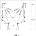
- the overall system architecture assumes an NG-RAN (Next Generation-Radio Access Network) that includes gNBs.
- the gNB provides the NG-radio access user plane (SDAP/PDCP/RLC/MAC/PHY) and control plane (RRC) protocol terminations towards the UE.
- SDAP/PDCP/RLC/MAC/PHY NG-radio access user plane
- RRC control plane
- the gNBs are interconnected with each other by means of the Xn interface.
- the gNBs are also connected by means of the Next Generation (NG) interface to the NGC (Next Generation Core), more specifically to the AMF (Access and Mobility Management Function) (e.g., a particular core entity performing the AMF) by means of the NG-C interface and to the UPF (User Plane Function) (e.g., a particular core entity performing the UPF) by means of the NG-U interface.
- NG Next Generation
- AMF Access and Mobility Management Function
- UPF User Plane Function
- the NG-RAN architecture is illustrated in FIG. 11 (see e.g., 3GPP TS 38.300 v15.6.0, section 4).
- the user plane protocol stack for NR includes the PDCP (Packet Data Convergence Protocol, see section 6.4 of TS 38.300), RLC (Radio Link Control, see section 6.3 of TS 38.300) and MAC (Medium Access Control, see section 6.2 of TS 38.300) sublayers, which are terminated in the gNB on the network side. Additionally, a new Access Stratum (AS) sublayer (SDAP, Service Data Adaptation Protocol) is introduced above the PDCP (see e.g., sub-clause 6.5 of 3GPP TS 38.300).
- AS Access Stratum
- SDAP Service Data Adaptation Protocol
- a control plane protocol stack is also defined for NR (see for instance TS 38.300, section 4.4.2).
- An overview of the Layer 2 functions is given in sub-clause 6 of TS 38.300.
- the functions of the PDCP, RLC, and MAC sublayers are listed respectively in sections 6.4, 6.3, and 6.2 of TS 38.300.
- the functions of the RRC layer are listed in sub-clause 7 of TS 38.300.
- the Medium-Access-Control layer handles logical-channel multiplexing, and scheduling and scheduling-related functions, including handling of different numerologies.
- the physical layer is for example responsible for coding, PHY HARQ processing, modulation, multi-antenna processing, and mapping of the signal to the appropriate physical time-frequency resources.
- the physical layer also handles mapping of transport channels to physical channels.
- the physical layer provides services to the MAC layer in the form of transport channels.
- a physical channel corresponds to the set of time-frequency resources used for transmission of a particular transport channel, and each transport channel is mapped to a corresponding physical channel.
- Examples of the physical channel include a Physical Random Access Channel (PRACH), a Physical Uplink Shared Channel (PUSCH), and a Physical Uplink Control Channel (PUCCH) as uplink physical channels, and a Physical Downlink Shared Channel (PDSCH), a Physical Downlink Control Channel (PDCCH), and a Physical Broadcast Channel (PBCH) as downlink physical channels.
- PRACH Physical Random Access Channel
- PUSCH Physical Uplink Shared Channel
- PUCCH Physical Uplink Control Channel
- PDSCH Physical Downlink Shared Channel
- PDCCH Physical Downlink Control Channel
- PBCH Physical Broadcast Channel
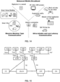
- Use cases/deployment scenarios for NR could include enhanced mobile broadband (eMBB), ultra-reliable low-latency communications (URLLC), and massive machine type communication (mMTC), which have diverse requirements in terms of data rates, latency, and coverage.
- eMBB enhanced mobile broadband
- URLLC ultra-reliable low-latency communications
- mMTC massive machine type communication
- eMBB is expected to support peak data rates (20 Gbps for downlink and 10 Gbps for uplink) and user-experienced data rates in the order of three times what is offered by IMT-Advanced.
- URLLC the tighter requirements are put on ultra-low latency (0.5 ms for UL and DL each for user plane latency) and high reliability (1-10-5 within 1 ms).
- mMTC may preferably require high connection density (1,000,000 devices/km 2 in an urban environment), large coverage in harsh environments, and extremely long-life battery for low cost devices (15 years).
- the OFDM numerology e.g., subcarrier spacing, OFDM symbol duration, cyclic prefix (CP) duration, and number of symbols per scheduling interval
- low-latency services may preferably require a shorter symbol duration (and thus larger subcarrier spacing) and/or fewer symbols per scheduling interval (aka, TTI) than an mMTC service.
- deployment scenarios with large channel delay spreads may preferably require a longer CP duration than scenarios with short delay spreads.
- the subcarrier spacing should be optimized accordingly to retain the similar CP overhead.
- NR may support more than one value of subcarrier spacing.
- the term "resource element" can be used to denote a minimum resource unit being composed of one subcarrier for the length of one OFDM/SC-FDMA symbol.
- a resource grid of subcarriers and OFDM symbols is defined respectively for uplink and downlink.
- Each element in the resource grid is called a resource element and is identified based on the frequency index in the frequency domain and the symbol position in the time domain (see 3GPP TS 38.211 v15.6.0).
- FIG. 12 illustrates the functional split between the NG-RAN and the 5GC.
- a logical node of the NG-RAN is gNB or ng-eNB.
- the 5GC includes logical nodes AMF, UPF, and SMF.
- gNB and ng-eNB hosts the following main functions:
- the Access and Mobility Management Function hosts the following main functions:
- UPF User Plane Function
- Session Management Function hosts the following main functions:
- FIG. 13 illustrates some interactions between a UE, gNB, and AMF (a 5GC Entity) performed in the context of a transition of the UE from RRC_IDLE to RRC_CONNECTED for the NAS part (see TS 38 300 v15.6.0).
- AMF a 5GC Entity
- the RRC is higher layer signaling (protocol) used to configure the UE and gNB.
- the AMF prepares UE context data (which includes, for example, a PDU session context, security key, UE Radio Capability, UE Security Capabilities, and the like) and sends it to the gNB with an INITIAL CONTEXT SETUP REQUEST.
- the gNB activates the AS security with the UE. This activation is performed by the gNB transmitting to the UE a SecurityModeCommand message and by the UE responding to the gNB with the SecurityModeComplete message.
- the gNB performs the reconfiguration to setup the Signaling Radio Bearer 2, SRB2, and Data Radio Bearer (s), DRB (s) by means of transmitting to the UE the RRCReconfiguration message and, in response, receiving by the gNB the RRCReconfigurationComplete from the UE.
- the steps relating to the RRCReconfiguration are skipped since SRB2 and DRBs are not set up.
- the gNB informs the AMF that the setup procedure is completed with INITIAL CONTEXT SETUP RESPONSE.
- the present disclosure provides a 5th Generation Core (5GC) entity (e.g., AMF, SMF, or the like) including control circuitry, which, in operation, establishes a Next Generation (NG) connection with a gNodeB, and a transmitter, which, in operation, transmits an initial context setup message to the gNodeB via the NG connection such that a signaling radio bearer between the gNodeB and a User Equipment (UE) is configured up.
- the gNodeB transmits Radio Resource Control (RRC) signaling including a resource allocation configuration Information Element (IE) to the UE via the signaling radio bearer.
- RRC Radio Resource Control
- IE resource allocation configuration Information Element
- FIG. 14 illustrates some of the use cases for 5G NR.
- 3GPP NR 3rd generation partnership project new radio
- 3GPP NR 3rd generation partnership project new radio
- three use cases are being considered that have been envisaged to support a wide variety of services and applications by IMT-2020.
- the specification for the phase 1 of enhanced mobile-broadband (eMBB) has been concluded.
- eMBB enhanced mobile-broadband
- URLLC ultra-reliable and low-latency communications
- mMTC massive machine-type communications
- FIG. 14 illustrates some examples of envisioned usage scenarios for IMT for 2020 and beyond (see e.g., ITU-R M.2083 FIG. 2 ).
- the URLLC use case has stringent requirements for capabilities such as throughput, latency and availability.
- the URLLC use case has been envisioned as one of the enablers for future vertical applications such as wireless control of industrial manufacturing or production processes, remote medical surgery, distribution automation in a smart grid, transportation safety, etc.
- Ultra-reliability for URLLC is to be supported by identifying the techniques to meet the requirements configured by TR 38.913.
- key requirements include a target user plane latency of 0.5 ms for UL (uplink) and 0.5 ms for DL (downlink).
- the general URLLC requirement for one transmission of a packet is a BLER (block error rate) of 1E-5 for a packet size of 32 bytes with a user plane latency of 1 ms.
- NR URLLC NR URLLC key requirements.
- Augmented Reality/Virtual Reality (AR/VR) Augmented Reality/Virtual Reality
- e-health e-safety
- mission-critical applications e-critical applications
- technology enhancements targeted by NR URLLC aim at latency improvement and reliability improvement.
- Technology enhancements for latency improvement include configurable numerology, non slot-based scheduling with flexible mapping, grant free (configured grant) uplink, slot-level repetition for data channels, and downlink pre-emption.
- Pre-emption means that a transmission for which resources have already been allocated is stopped, and the already allocated resources are used for another transmission that has been requested later, but has lower latency/higher priority requirements. Accordingly, the already granted transmission is pre-empted by a later transmission.
- Pre-emption is applicable independent of the particular service type. For example, a transmission for a service-type A (URLLC) may be pre-empted by a transmission for a service type B (such as eMBB).
- Technology enhancements with respect to reliability improvement include dedicated CQI/MCS tables for the target BLER of 1E-5.
- mMTC massive machine type communication
- PDCCH Physical Downlink Control Channel
- UCI Uplink Control Information
- HARQ Hybrid Automatic Repeat Request
- CSI feedback enhancements PUSCH enhancements related to mini-slot level hopping and retransmission/repetition enhancements are possible.
- mini-slot refers to a Transmission Time Interval (TTI) including a smaller number of symbols than a slot (a slot comprising fourteen symbols).
- the 5G QoS (Quality of Service) model is based on QoS flows and supports both QoS flows that require guaranteed flow bit rate (GBR QoS flows) and QoS flows that do not require guaranteed flow bit rate (non-GBR QoS Flows).
- GRR QoS flows QoS flows that require guaranteed flow bit rate
- non-GBR QoS Flows QoS flows that do not require guaranteed flow bit rate
- the QoS flow is thus the finest granularity of QoS differentiation in a PDU session.
- a QoS flow is identified within a PDU session by a QoS flow ID (QFI) carried in an encapsulation header over NG-U interface.
- QFI QoS flow ID
- 5GC For each UE, 5GC establishes one or more PDU Sessions. For each UE, the NG-RAN establishes at least one Data Radio Bearer (DRB) together with the PDU Session, e.g., as illustrated above with reference to FIG. 13 . Further, additional DRB (s) for QoS flow (s) of that PDU session can be subsequently configured (it is up to NG-RAN when to do so).
- DRB Data Radio Bearer
- additional DRB (s) for QoS flow (s) of that PDU session can be subsequently configured (it is up to NG-RAN when to do so).
- the NG-RAN maps packets belonging to different PDU sessions to different DRBs.
- NAS level packet filters in the UE and in the 5GC associate UL and DL packets with QoS Flows
- AS-level mapping rules in the UE and in the NG-RAN associate UL and DL QoS Flows with DRBs.
- FIG. 15 illustrates a 5G NR non-roaming reference architecture (see TS 23.501 v16.1.0, section 4.23).
- An Application Function e.g., an external application server hosting 5G services, exemplarily described in FIG. 14 , interacts with the 3GPP Core Network in order to provide services, for example to support application influence on traffic routing, accessing Network Exposure Function (NEF) or interacting with the Policy framework for policy control (see Policy Control Function, PCF), e.g., QoS control.
- PCF Policy Control Function
- Application Functions considered to be trusted by the operator can be allowed to interact directly with relevant Network Functions.
- Application Functions not allowed by the operator to access directly the Network Functions use the external exposure framework via the NEF to interact with relevant Network Functions.
- FIG. 15 illustrates further functional units of the 5G architecture, namely Network Slice Selection Function (NSSF), Network Repository Function (NRF), Unified Data Management (UDM), Authentication Server Function (AUSF), Access and Mobility Management Function (AMF), Session Management Function (SMF), and Data Network (DN), e.g., operator services, Internet access or 3rd party services. All of or a part of the core network functions and the application services may be deployed and running on cloud computing environments.
- NSF Network Slice Selection Function
- NRF Network Repository Function
- UDM Unified Data Management
- AUSF Authentication Server Function
- AMF Access and Mobility Management Function
- SMSF Session Management Function
- DN Data Network
- an application server for example, AF of the 5G architecture
- a transmitter which, in operation, transmits a request containing a QoS requirement for at least one of URLLC, eMMB and mMTC services to at least one of functions (for example NEF, AMF, SMF, PCF,UPF, etc.) of the 5GC to establish a PDU session including a radio bearer between a gNodeB and a UE in accordance with the QoS requirement; and control circuitry, which, in operation, performs the services using the established PDU session.
- functions for example NEF, AMF, SMF, PCF,UPF, etc.
- the present disclosure can be realized by software, hardware, or software in cooperation with hardware.
- Each functional block used in the description of each embodiment described above can be partly or entirely realized by an LSI such as an integrated circuit, and each process described in the each embodiment may be controlled partly or entirely by the same LSI or a combination of LSIs.
- the LSI may be individually formed as chips, or one chip may be formed so as to include a part or all of the functional blocks.
- the LSI may include a data input and output coupled thereto.
- the LSI herein may be referred to as an IC, a system LSI, a super LSI, or an ultra LSI depending on a difference in the degree of integration.
- the technique of implementing an integrated circuit is not limited to the LSI and may be realized by using a dedicated circuit, a general-purpose processor, or a special-purpose processor.
- a FPGA Field Programmable Gate Array
- a reconfigurable processor in which the connections and the settings of circuit cells disposed inside the LSI can be reconfigured may be used.
- the present disclosure can be realized as digital processing or analogue processing.
- the present disclosure can be realized by any kind of apparatus, device or system having a function of communication, which is referred to as a communication apparatus.
- the communication apparatus may comprise a transceiver and processing/control circuitry.
- the transceiver may comprise and/or function as a receiver and a transmitter.
- the transceiver, as the transmitter and receiver, may include an RF (radio frequency) module and one or more antennas.
- the RF module may include an amplifier, an RF modulator/demodulator, or the like.
- Such a communication apparatus include a phone (e.g., cellular (cell) phone, smart phone), a tablet, a personal computer (PC) (e.g., laptop, desktop, netbook), a camera (e.g., digital still/video camera), a digital player (digital audio/video player), a wearable device (e.g., wearable camera, smart watch, tracking device), a game console, a digital book reader, a telehealth/telemedicine (remote health and medicine) device, and a vehicle providing communication functionality (e.g., automotive, airplane, ship), and various combinations thereof.
- a phone e.g., cellular (cell) phone, smart phone
- a tablet e.g., a personal computer (PC) (e.g., laptop, desktop, netbook)
- a camera e.g., digital still/video camera
- a digital player digital audio/video player
- a wearable device e.g., wearable camera, smart watch, tracking device
- the communication apparatus is not limited to be portable or movable, and may also include any kind of apparatus, device or system being non-portable or stationary, such as a smart home device (e.g., an appliance, lighting, smart meter, control panel), a vending machine, and any other "things” in a network of an "Internet of Things (IoT).”
- a smart home device e.g., an appliance, lighting, smart meter, control panel
- vending machine e.g., a vending machine, and any other "things” in a network of an "Internet of Things (IoT).”
- IoT Internet of Things
- the communication may include exchanging data through, for example, a cellular system, a wireless LAN system, a satellite system, etc., and various combinations thereof.
- the communication apparatus may comprise a device such as a controller or a sensor which is coupled to a communication device performing a function of communication described in the present disclosure.
- the communication apparatus may comprise a controller or a sensor that generates control signals or data signals which are used by a communication device performing a communication function of the communication apparatus.
- the communication apparatus also may include an infrastructure facility, such as, e.g., a base station, an access point, and any other apparatus, device or system that communicates with or controls apparatuses such as those in the above non-limiting examples.
- an infrastructure facility such as, e.g., a base station, an access point, and any other apparatus, device or system that communicates with or controls apparatuses such as those in the above non-limiting examples.
- a communication apparatus includes: control circuitry, which, in operation, determines, based on a type of an identifier used for a control signal performing dynamic scheduling, a configuration of enabling and disabling of feedback in retransmission control of the dynamic scheduling; and transmission circuitry, which, in operation, performs transmission processing on a signal of the feedback based on the configuration of enabling and disabling of feedback.
- control circuitry determines a first configuration configured per semi-static scheduling as the configuration of enabling and disabling of feedback when the identifier is a first identifier, and determines a second configuration configured per retransmission process as the configuration of enabling and disabling of feedback when the identifier is a second identifier different from the first identifier.
- retransmission of data in the semi-static scheduling is performed by the dynamic scheduling
- the first identifier is used for scrambling the control signal scheduling retransmission of data in the semi-static scheduling
- the second identifier is used for scrambling the control signal scheduling data different from the data in the semi-static scheduling.
- control circuitry determines, when the identifier is the first identifier, a configuration corresponding to a retransmission process number used for the dynamic scheduling among a plurality of the first configurations as the configuration of enabling and disabling of feedback.
- the control circuitry determines, when the identifier is a first identifier, a first configuration configured per semi-static scheduling as the configuration of enabling and disabling of feedback, and determines, when the identifier is a second identifier different from the first identifier, the first configuration as the configuration of enabling and disabling of feedback in a case where a retransmission process number used for the dynamic scheduling is used for the semi-static scheduling, and determines, when the identifier is a second identifier different from the first identifier, a second configuration configured per retransmission process as the configuration of enabling and disabling of feedback in a case where the retransmission process number used for the dynamic scheduling is not used for the semi-static scheduling.
- control circuitry determines, based on the type of the identifier, either one of a first configuration configured per semi-static scheduling and a second configuration configured per retransmission process as the configuration of enabling and disabling of feedback, and the first configuration is determined based on the second configuration corresponding to one of retransmission process numbers used for the semi-static scheduling.
- control circuitry determines, based on the type of the identifier, either one of a first configuration configured per semi-static scheduling and a second configuration configured per retransmission process as the configuration of enabling and disabling of feedback, and the control circuitry does not perform reception processing on retransmission data in the semi-static scheduling when the first configuration is disabling of feedback.
- a communication apparatus includes: control circuitry, which, in operation, determines, based on a type of an identifier used for a control signal performing dynamic scheduling, a configuration of enabling and disabling of feedback in retransmission control of the dynamic scheduling; and reception circuitry, which, in operation, performs reception processing on a signal of the feedback based on the configuration of enabling and disabling of feedback.
- a communication apparatus determines, based on a type of an identifier used for a control signal performing dynamic scheduling, a configuration of enabling and disabling of feedback in retransmission control of the dynamic scheduling, and performs transmission processing on a signal of the feedback based on the configuration of enabling and disabling of feedback.
- a communication apparatus determines, based on a type of an identifier used for a control signal performing dynamic scheduling, a configuration of enabling and disabling of feedback in retransmission control of the dynamic scheduling, and performs reception processing on a signal of the feedback based on the configuration of enabling and disabling of feedback
- One aspect of the present disclosure is useful in radio communication systems.
Landscapes
- Engineering & Computer Science (AREA)
- Computer Networks & Wireless Communication (AREA)
- Signal Processing (AREA)
- Mobile Radio Communication Systems (AREA)
Applications Claiming Priority (2)
| Application Number | Priority Date | Filing Date | Title |
|---|---|---|---|
| JP2021166187 | 2021-10-08 | ||
| PCT/JP2022/019831 WO2023058264A1 (fr) | 2021-10-08 | 2022-05-10 | Dispositif de communication et procédé de communication |
Publications (2)
| Publication Number | Publication Date |
|---|---|
| EP4415420A1 true EP4415420A1 (fr) | 2024-08-14 |
| EP4415420A4 EP4415420A4 (fr) | 2025-02-19 |
Family
ID=85804066
Family Applications (1)
| Application Number | Title | Priority Date | Filing Date |
|---|---|---|---|
| EP22878137.3A Withdrawn EP4415420A4 (fr) | 2021-10-08 | 2022-05-10 | Dispositif de communication et procédé de communication |
Country Status (4)
| Country | Link |
|---|---|
| US (1) | US20250015936A1 (fr) |
| EP (1) | EP4415420A4 (fr) |
| JP (1) | JPWO2023058264A1 (fr) |
| WO (1) | WO2023058264A1 (fr) |
Families Citing this family (1)
| Publication number | Priority date | Publication date | Assignee | Title |
|---|---|---|---|---|
| WO2023132729A1 (fr) * | 2022-01-10 | 2023-07-13 | 엘지전자 주식회사 | Procédé et appareil permettant d'effectuer une transmission et une réception en liaison montante dans un système de communication sans fil |
Family Cites Families (6)
| Publication number | Priority date | Publication date | Assignee | Title |
|---|---|---|---|---|
| US10541390B2 (en) | 2015-05-18 | 2020-01-21 | Semiconductor Energy Laboratory Co., Ltd. | Power storage unit and electronic device |
| CN114208098B (zh) * | 2019-08-14 | 2025-01-14 | 索尼集团公司 | 终端设备、基站设备、终端设备的控制方法以及基站设备的控制方法 |
| CN112399576A (zh) * | 2019-08-16 | 2021-02-23 | 索尼公司 | 用于无线通信的电子设备和方法、计算机可读存储介质 |
| CN113839757A (zh) * | 2020-06-24 | 2021-12-24 | 北京三星通信技术研究有限公司 | 上行控制信息发送方法、接收方法、终端及基站 |
| CN116964970A (zh) * | 2020-11-24 | 2023-10-27 | 欧芬诺有限责任公司 | 多播和广播服务的组调度 |
| CN118057969A (zh) * | 2021-09-30 | 2024-05-21 | 富士通株式会社 | 信息反馈方法以及装置 |
-
2022
- 2022-05-10 EP EP22878137.3A patent/EP4415420A4/fr not_active Withdrawn
- 2022-05-10 WO PCT/JP2022/019831 patent/WO2023058264A1/fr not_active Ceased
- 2022-05-10 JP JP2023552688A patent/JPWO2023058264A1/ja active Pending
- 2022-05-10 US US18/697,936 patent/US20250015936A1/en active Pending
Also Published As
| Publication number | Publication date |
|---|---|
| EP4415420A4 (fr) | 2025-02-19 |
| JPWO2023058264A1 (fr) | 2023-04-13 |
| WO2023058264A1 (fr) | 2023-04-13 |
| US20250015936A1 (en) | 2025-01-09 |
Similar Documents
| Publication | Publication Date | Title |
|---|---|---|
| US20230261830A1 (en) | Terminal, base station, and communication method | |
| US12074707B2 (en) | Mobile station, base station, reception method, and transmission method | |
| US20230371029A1 (en) | Terminal, base station, and communication method | |
| US20250097908A1 (en) | Communication device, and communication method | |
| US20230291520A1 (en) | Terminal, base station, and communication method | |
| US20260088958A1 (en) | Base station, terminal, and communication method | |
| US20240187136A1 (en) | Base station, terminal, and communication method | |
| US20250015927A1 (en) | Base station, terminal, and communication method | |
| US20240340106A1 (en) | Base station, terminal, and communication method | |
| US20240188053A1 (en) | Terminal, base station, and communication method | |
| US12557042B2 (en) | Terminal and communication method | |
| US20230388982A1 (en) | Communication device and communication method | |
| EP4415420A1 (fr) | Dispositif de communication et procédé de communication | |
| US12609795B2 (en) | Terminal, base station, and communication method | |
| US20250212219A1 (en) | Terminal, base station, and communication method | |
| US20240357586A1 (en) | Joint channel estimation for multiple transport blocks | |
| US20240333428A1 (en) | Terminal, base station, and communication method | |
| US20230300859A1 (en) | Terminal and sidelink communication control method | |
| US20260019869A1 (en) | Terminal, base station, and communication method | |
| US20240430038A1 (en) | Terminal, base station, and communication method | |
| EP4344087A1 (fr) | Mécanismes de configuration de transmission pour un répéteur commandé par réseau | |
| US20250330958A1 (en) | Terminal, base station, communication method, and integrated circuit | |
| US12621105B2 (en) | Communication device and communication method | |
| US20250008528A1 (en) | Base station, terminal, and communication method | |
| US20260006604A1 (en) | Terminal, base station, and communication method |
Legal Events
| Date | Code | Title | Description |
|---|---|---|---|
| STAA | Information on the status of an ep patent application or granted ep patent |
Free format text: STATUS: THE INTERNATIONAL PUBLICATION HAS BEEN MADE |
|
| PUAI | Public reference made under article 153(3) epc to a published international application that has entered the european phase |
Free format text: ORIGINAL CODE: 0009012 |
|
| STAA | Information on the status of an ep patent application or granted ep patent |
Free format text: STATUS: REQUEST FOR EXAMINATION WAS MADE |
|
| 17P | Request for examination filed |
Effective date: 20240404 |
|
| AK | Designated contracting states |
Kind code of ref document: A1 Designated state(s): AL AT BE BG CH CY CZ DE DK EE ES FI FR GB GR HR HU IE IS IT LI LT LU LV MC MK MT NL NO PL PT RO RS SE SI SK SM TR |
|
| DAV | Request for validation of the european patent (deleted) | ||
| DAX | Request for extension of the european patent (deleted) | ||
| A4 | Supplementary search report drawn up and despatched |
Effective date: 20250117 |
|
| RIC1 | Information provided on ipc code assigned before grant |
Ipc: H04W 72/12 20230101ALI20250113BHEP Ipc: H04L 1/16 20230101ALI20250113BHEP Ipc: H04W 28/04 20090101AFI20250113BHEP |
|
| STAA | Information on the status of an ep patent application or granted ep patent |
Free format text: STATUS: THE APPLICATION IS DEEMED TO BE WITHDRAWN |
|
| 18D | Application deemed to be withdrawn |
Effective date: 20250805 |