EP4416193B1 - Procédé de préparation de polymères d'éthylène dans une polymérisation en suspension - Google Patents
Procédé de préparation de polymères d'éthylène dans une polymérisation en suspension Download PDFInfo
- Publication number
- EP4416193B1 EP4416193B1 EP22844040.0A EP22844040A EP4416193B1 EP 4416193 B1 EP4416193 B1 EP 4416193B1 EP 22844040 A EP22844040 A EP 22844040A EP 4416193 B1 EP4416193 B1 EP 4416193B1
- Authority
- EP
- European Patent Office
- Prior art keywords
- reactor
- polymerization
- reactor system
- heat exchangers
- cleaning
- Prior art date
- Legal status (The legal status is an assumption and is not a legal conclusion. Google has not performed a legal analysis and makes no representation as to the accuracy of the status listed.)
- Active
Links
Images

Classifications
-
- C—CHEMISTRY; METALLURGY
- C08—ORGANIC MACROMOLECULAR COMPOUNDS; THEIR PREPARATION OR CHEMICAL WORKING-UP; COMPOSITIONS BASED THEREON
- C08F—MACROMOLECULAR COMPOUNDS OBTAINED BY REACTIONS ONLY INVOLVING CARBON-TO-CARBON UNSATURATED BONDS
- C08F210/00—Copolymers of unsaturated aliphatic hydrocarbons having only one carbon-to-carbon double bond
- C08F210/16—Copolymers of ethene with alpha-alkenes, e.g. EP rubbers
-
- C—CHEMISTRY; METALLURGY
- C08—ORGANIC MACROMOLECULAR COMPOUNDS; THEIR PREPARATION OR CHEMICAL WORKING-UP; COMPOSITIONS BASED THEREON
- C08F—MACROMOLECULAR COMPOUNDS OBTAINED BY REACTIONS ONLY INVOLVING CARBON-TO-CARBON UNSATURATED BONDS
- C08F2/00—Processes of polymerisation
- C08F2/002—Scale prevention in a polymerisation reactor or its auxiliary parts
-
- C—CHEMISTRY; METALLURGY
- C08—ORGANIC MACROMOLECULAR COMPOUNDS; THEIR PREPARATION OR CHEMICAL WORKING-UP; COMPOSITIONS BASED THEREON
- C08F—MACROMOLECULAR COMPOUNDS OBTAINED BY REACTIONS ONLY INVOLVING CARBON-TO-CARBON UNSATURATED BONDS
- C08F2/00—Processes of polymerisation
- C08F2/002—Scale prevention in a polymerisation reactor or its auxiliary parts
- C08F2/007—Scale prevention in the auxiliary parts
-
- C—CHEMISTRY; METALLURGY
- C08—ORGANIC MACROMOLECULAR COMPOUNDS; THEIR PREPARATION OR CHEMICAL WORKING-UP; COMPOSITIONS BASED THEREON
- C08F—MACROMOLECULAR COMPOUNDS OBTAINED BY REACTIONS ONLY INVOLVING CARBON-TO-CARBON UNSATURATED BONDS
- C08F2/00—Processes of polymerisation
- C08F2/008—Processes of polymerisation cleaning reaction vessels using chemicals
-
- C—CHEMISTRY; METALLURGY
- C08—ORGANIC MACROMOLECULAR COMPOUNDS; THEIR PREPARATION OR CHEMICAL WORKING-UP; COMPOSITIONS BASED THEREON
- C08F—MACROMOLECULAR COMPOUNDS OBTAINED BY REACTIONS ONLY INVOLVING CARBON-TO-CARBON UNSATURATED BONDS
- C08F2/00—Processes of polymerisation
- C08F2/01—Processes of polymerisation characterised by special features of the polymerisation apparatus used
-
- C—CHEMISTRY; METALLURGY
- C08—ORGANIC MACROMOLECULAR COMPOUNDS; THEIR PREPARATION OR CHEMICAL WORKING-UP; COMPOSITIONS BASED THEREON
- C08F—MACROMOLECULAR COMPOUNDS OBTAINED BY REACTIONS ONLY INVOLVING CARBON-TO-CARBON UNSATURATED BONDS
- C08F2/00—Processes of polymerisation
- C08F2/04—Polymerisation in solution
- C08F2/06—Organic solvent
-
- C—CHEMISTRY; METALLURGY
- C08—ORGANIC MACROMOLECULAR COMPOUNDS; THEIR PREPARATION OR CHEMICAL WORKING-UP; COMPOSITIONS BASED THEREON
- C08F—MACROMOLECULAR COMPOUNDS OBTAINED BY REACTIONS ONLY INVOLVING CARBON-TO-CARBON UNSATURATED BONDS
- C08F2/00—Processes of polymerisation
- C08F2/12—Polymerisation in non-solvents
- C08F2/14—Organic medium
-
- C—CHEMISTRY; METALLURGY
- C08—ORGANIC MACROMOLECULAR COMPOUNDS; THEIR PREPARATION OR CHEMICAL WORKING-UP; COMPOSITIONS BASED THEREON
- C08F—MACROMOLECULAR COMPOUNDS OBTAINED BY REACTIONS ONLY INVOLVING CARBON-TO-CARBON UNSATURATED BONDS
- C08F2500/00—Characteristics or properties of obtained polyolefins; Use thereof
- C08F2500/05—Bimodal or multimodal molecular weight distribution
Definitions
- the present disclosure provides a process for polymerizing ethylene or copolymerizing ethylene and one or more C 3 -C 12 -1 alkenes in a slurry polymerization.
- the present disclosure provides in particular a process for polymerizing ethylene or copolymerizing ethylene and one or more C 3 -C 12 -1 alkenes in a slurry polymerization which is carried out in a reactor system comprising a polymerization reactor and one or more heat exchangers located outside the polymerization reactor.
- the present disclosure provides furthermore a process for polymerizing ethylene or copolymerizing ethylene and one or more C 3 -C 12 -1 alkenes in a slurry polymerization comprising a cleaning step.
- Slurry polymerization processes for preparing ethylene polymers are established methods for producing ethylene polymers and, for example, disclosed in EP 0 905 152 A1 or WO 2012/028591 A1 . Such processes are often carried out in a series of reactors and so allow to set different reaction conditions in the polymerization reactors and thereby to produce different polymer compositions in the individual polymerization reactors. Accordingly produced multimodal ethylene copolymers are characterized by having, for example, a good combination of product properties and processability. Slurry processes for preparing ethylene polymers commonly employ a hydrocarbon or a hydrocarbon mixture as diluent.
- the slurry is thus commonly a suspension of ethylene polymer particles in a liquid medium which comprises, besides the hydrocarbon diluent as main component, also further components like dissolved ethylene, comonomers, aluminum alkyls, and hydrogen and dissolved reaction products like oligomers and waxes.
- a liquid medium which comprises, besides the hydrocarbon diluent as main component, also further components like dissolved ethylene, comonomers, aluminum alkyls, and hydrogen and dissolved reaction products like oligomers and waxes.
- Slurry polymerization systems for preparing ethylene polymers can use external heat exchangers in a reactor recirculation loop to remove heat produced in the ethylene polymerization reactions.
- a reduced solubility at lower temperature low molecular weight waxes, which are produced in the reactors as a byproduct, can solidify when the slurry flows through the cooler and contacts the cold walls of the heat exchangers. This may foul the heat exchangers, i.e. may cause a build-up of an oligomeric or polymeric layer on the cold walls of the heat exchangers, decreasing the heat transfer in the heat exchanger and reducing their efficiency in heat removal.
- Such build-up of non-desired walls layers can also occur at the walls of the polymerization reactors.
- WO 2015/197561 A1 discloses a process for the preparation of polyethylene in which external heat exchangers are cooled by a coolant having a temperature of 29°C or higher. Nonetheless, the build-up of wall layers cannot be fully avoided and a cleaning of the polymerization system may be needed from time to time.
- Methods for cleaning polymerization systems for preparing ethylene polymers include flushing the polymerization system with an hydrocarbon at ambient temperature. Such flushing however only allows to remove loose particles at the inner surface walls.
- Another option is mechanical cleaning, for example by hydro-jet devices.
- the inner surface of the polymerization system may be negatively affected, for example by rust formation. Additionally, the mechanical cleaning requires a lot of efforts. An elaborated preparation of the reactor system is needed so that the reactor can be opened, the reactor system has to be entered and afterwards all traces of water and humidity need to be removed from the reactor system.
- a preferred method for cleaning polymerization systems for preparing ethylene polymers is cleaning the reactor system with hot hydrocarbons.
- WO 2015/197561 A1 discloses that for cleaning the heat exchangers of a reactor system comprising a polymerization reactor and one or more heat exchangers located outside the polymerization reactor, a heat exchanger is typically isolated and a hot hydrocarbon like hexane, usually of about 155°C, is circulated through the heat exchanger to re-dissolve deposits.
- US 10,370,307 B2 discloses a process for the oligomerization of ethylene into alphaolefins, comprising a step for the oligomerization of ethylene, a step for the deactivation of the catalyst and a step for separation of the products.
- the reactor is provided with a cooling loop by means of which at least a portion of the reaction effluent is moved through at least two switchable heat exchangers, said heat exchangers being cleaned alternately by means of an integrated cleaning device.
- Cleaning a reactor system with hot hydrocarbons has a high cleaning efficiency, does not demand opening of the reactor system, does not affect the inner surface of the polymerization system and can be carried out in relatively short time with a limited amount of manpower.
- For cleaning the reactor system with hot hydrocarbons it is needed to replace the slurry within the reactor system by a hydrocarbon or a hydrocarbon mixture and then heat the hydrocarbon to the appropriate temperature. This may be carried out by using the external heat exchangers and/or the reactor cooling jackets as heaters, and instead of cooling these tempering devices by a coolant, the devices are heated, commonly by using low or medium pressure steam.
- using steam as heating medium does not allow a smooth and easy control of the temperature of the reactor system and steam hammering with cavitation cannot be avoided.
- tempering medium from a coolant, commonly water, to steam and vice versa may result in corrosion of the external heat exchangers and polymerization reactor cooling jackets. Corrosion in heat exchangers on the one hand leads to reduced heat transfer due to increase roughness of the wall surface and, on the other hand, severe corrosion may also lead to leakage of tempering medium requiring a replacement of the heat exchangers or of components of the heat exchangers from time to time.
- a coolant commonly water
- the present disclosure provides a process for polymerizing ethylene or copolymerizing ethylene and one or more C 3 -C 12 -1-alkenes in a slurry polymerization at temperatures of from 40 to 150°C and pressures from 0.1 to 5 MPa in the presence of a polymerization catalyst,
- the reactor system is a part of a series of two, three or more reactor systems comprising each a polymerization reactor and one or more first heat exchangers located outside the polymerization reactor for cooling or heating the reactor content.
- the first heat exchangers are double pipe heat exchangers, preferably having a surface roughness R a of less than 5 ⁇ m determined according to ASME B46.1.
- the polymerization reactors are further equipped at the reactor outside with tempering jackets.
- tempering jackets consist of a series of half-pipes attached to the outside of the polymerization reactors.
- the tempering medium for cooling or heating the tempering jacket is the tempering medium for cooling or heating the one or more first heat exchangers.
- the process comprises a cleaning step for cleaning the polymerization reactor, for cleaning the one or more first heat exchangers or for cleaning the polymerization reactor and the one or more first heat exchangers, wherein the cleaning step comprises the sub-steps of
- a sub-step of flushing the reactor system with hydrocarbon diluent is carried out.
- the hydrocarbon solvent is introduced into the emptied reactor system until a liquid level of the cleaning fill within the polymerization reactor is at least as high as the liquid level of the slurry within the polymerization reactor during polymerization.
- the introduction of the hydrocarbon solvent into the reactor system is terminated after a cleaning fill within the reactor system has been formed and thereafter the maintenance of the cleaning fill within the reactor system at the temperature from 100°C to 180°C and the discharge of the cleaning fill from the reactor system occur without introduction of additional hydrocarbon solvent.
- hydrocarbon solvent is continuously introduced into the reactor system and cleaning fill is continuously discharged from the reactor system.
- the circulation of the cleaning fill from the polymerization reactor through the one or more first heat exchangers is terminated and the contents of the one or more first heat exchangers and the polymerization reactor are subsequently discharged.
- the cleaning fill discharged from the reactor system is transferred into an agitated evaporation vessel which is configured to allow withdrawal of hydrocarbon solvent by evaporation from a liquid medium comprising such hydrocarbon solvent.
- the discharge of the cleaning fill from the reactor system into the agitated distillation vessel occurs by a pressure difference between the cleaning fill within the reactor system and the agitated distillation vessel.
- the obtained ethylene polymers are bimodal or multimodal ethylene polymers.
- the present disclosure provides a process for polymerizing ethylene or copolymerizing ethylene and one or more C 3 -C 12 -1-alkenes in a slurry polymerization at temperatures from 40 to 150°C and pressures of from 0.1 to 20 MPa in the presence of a polymerization catalyst.
- the C 3 -C 12 -1-alkenes may be linear or branched.
- C 3 -C 12 -1-alkenes are linear C 3 -C 10 -1-alkenes such as propylene, 1-butene, 1-pentene, 1-hexene, 1-heptene, 1-octene, or 1-decene or branched C 2 -C 10 -1-alkenes such as 4-methyl-1-penten. It is also possible to polymerize ethylene with mixtures of two or more C 3 -C 12 -1-alkenes.
- Preferred comonomers are C 3 -C 8 -1-alkenes, in particular 1-butene, 1-pentene, 1-hexene, 1-heptene and/or 1-octene.
- the amount of units which are derived from incorporated comonomers is preferably from 0.01 wt.% to 25 wt.%, more preferably from 0.05 wt.% to 15 wt.% and in particular from 0.1 wt.% to 12 wt.%.
- Particular preference is given to processes in which ethylene is copolymerized with from 0.1 wt.% to 12 wt.% of 1-hexene and/or 1-butene and especially from 0.1 wt.% to 12 wt.% of 1-butene.
- the polymerization can be carried out using all customary olefin polymerization catalysts. That means the polymerization can be carried out, for example, using Phillips catalysts based on chromium oxide, using titanium-based Ziegler- or Ziegler-Natta-catalysts, using singlesite catalysts, or using mixtures of such catalysts.
- single-site catalysts are catalysts based on chemically uniform transition metal coordination compounds.
- Such mixed catalysts are often designated as hybrid catalysts.
- the preparation and use of these catalysts for olefin polymerization are generally known.
- Preferred catalysts are of the Ziegler type, preferably comprising a compound of titanium or vanadium, a compound of magnesium and optionally an electron donor compound and/or a particulate inorganic oxide as a support material.
- Catalysts of the Ziegler type are usually polymerized in the presence of a cocatalyst.
- Preferred cocatalysts are organometallic compounds of metals of Groups 1, 2, 12, 13 or 14 of the Periodic Table of Elements, in particular organometallic compounds of metals of Group 13 and especially organoaluminum compounds.
- Preferred cocatalysts are for example organometallic alkyls, organometallic alkoxides, or organometallic halides.
- organometallic compounds comprise lithium alkyls, magnesium or zinc alkyls, magnesium alkyl halides, aluminum alkyls, silicon alkyls, silicon alkoxides and silicon alkyl halides. More preferably, the organometallic compounds comprise aluminum alkyls and magnesium alkyls. Still more preferably, the organometallic compounds comprise aluminum alkyls, most preferably trialkylaluminum compounds or compounds of this type in which an alkyl group is replaced by a halogen atom, for example by chlorine or bromine. Examples of such aluminum alkyls are trimethylaluminum, triethylaluminum, tri-isobutylaluminum, tri-n-hexylaluminum or diethylaluminum chloride or mixtures thereof.
- the process of the present disclosure is a polymerization process carried out as a slurry polymerization.
- slurry polymerizations which are also designated as suspension polymerizations, take place in a liquid medium which comprises a hydrocarbon diluent and in which the produced ethylene polymer is insoluble and forms solid particles.
- the otherwise liquid medium of the slurry can also be in supercritical state under the conditions within the polymerization reactor
- the solids content of the slurry is generally in the range of from 10 to 80 wt.%, preferably in the range of from 20 to 40 wt.%.
- hydrocarbon diluents are for example hydrocarbons having from 3 to 12 carbon atoms, and in particular saturated hydrocarbons like isobutane, butane, propane, isopentane, pentane, hexane or octane, or a mixture of these.
- the hydrocarbon diluent is a hydrocarbon mixture.
- hydrocarbon mixtures may have a boiling point range.
- the hydrocarbon diluent preferably has a boiling point which is significantly different from those of the monomers and comonomers used in order to make it possible for these starting materials to be recovered from a mixture by distillation.
- Such hydrocarbon diluents are for example hydrocarbons having a boiling point above 40°C or even above 60°C or mixtures comprising a high proportion of these hydrocarbons.
- the polymerization takes place in a liquid medium comprising more than 50 wt.% of saturated hydrocarbons having a boiling point of above 60°C at 0.1 MPa or even comprising more than 80 wt.% of saturated hydrocarbons having a boiling point of above 60°C at 0.1 MPa.
- the process of the present disclosure is carried out at temperatures in the range from 40 to 150°C, preferably from 50 to 130°C and particularly preferably from 60 to 90°C, and at pressures from 0.1 to 5 MPa and preferably from 0.15 to 3 MPa and particularly preferably from 0.2 to 2 MPa, wherein these pressures, as all pressures given in the present disclosure, have to be understood as being absolute pressures, i.e. pressure having the dimension MPa (abs).
- the polymerization is carried out in a series of at least two polymerization reactors which are connected in series.
- the number of reactors of such a series preferably the series consist of two, three or four reactors and most preferably of two or three reactors.
- the polymerization conditions in the polymerization reactors can differ, for example by the nature and/or the amount of comonomers or by different concentrations of polymerization auxiliaries such as hydrogen.
- the ethylene polymers are usually obtained as powder, that means in form of small particles.
- the particles which have usually a more or less regular morphology and size, depending on the catalyst morphology and size, and on polymerization conditions.
- the particles of the polyolefin powder usually have a mean diameter of from a few hundred to a few thousand micrometers.
- the mean particle diameter is usually from about 300 to about 1600 ⁇ m, and in the case of Ziegler type catalysts the mean particle diameter is usually from about 50 to about 3000 ⁇ m.
- Preferred polyolefin powders have a mean particle diameter of from 100 to 250 ⁇ m.
- the particle size distribution can, for example, advantageously be determined by sieving. Suitable technics are e.g. vibrating sieve analysis or sieve analysis under an air jet.
- the density of preferred ethylene polymers obtained by the process of the present disclosure is from 0.90 g/cm 3 to 0.97 g/cm 3 .
- the density is in the range of from 0.920 to 0.968 g/cm 3 and especially in the range of from 0.945 to 0.965 g/cm 3 .
- the density has to be understood as being the density determined according to DIN EN ISO 1183-1:2004, Method A (Immersion) with compression molded plaques of 2 mm thickness which were pressed at 180°C, 20MPa for 8 minutes with subsequent crystallization in boiling water for 30 minutes.
- the ethylene polymers prepared by the process of the present disclosure have a MFR 21.6 at a temperature of 190°C under a load of 21.6 kg, determined according to DIN EN ISO 1133:2005, condition G, from 0.5 to 300 g/10 min, more preferably from 1 to 100 g/10 min, even more preferably of from 1.2 to 100 g/10 min and in particular from 1.5 to 50 g/10 min.
- the ethylene polymers obtained by the process of the present disclosure can be monomodal, bimodal or multimodal ethylene polymers.
- the ethylene polymers are bimodal or multimodal ethylene polymers.
- multimodal hereby refers to the modality of the obtained ethylene copolymer and indicates that the ethylene copolymer comprises at least two fractions of polymer which are obtained under different reaction conditions, independently whether this modality can be recognized as separated maxima in a gel permeation chromatography (GPC) curve or not.
- the different polymerization conditions can, for example, be achieved by using different hydrogen concentrations and/or by using different comonomer concentrations in different polymerization reactors.
- Such polymers can be obtained from polymerizing olefins in a series of two or more polymerization reactors under different reaction conditions. It is however also possible to obtain such bimodal or multimodal polyolefins by employing mixed catalysts.
- the polyolefin can also have a comonomer distribution, wherein preferably the average comonomer content of polymer chains with a higher molecular weight is higher than the average comonomer content of polymer chains with a lower molecular weight.
- multimodal as used herein shall include also "bimodal".
- the polymerization is carried out in a series of polymerization reactors and an ethylene homopolymer, preferably a low molecular weight ethylene homopolymer, is prepared in the first polymerization reactor and an ethylene copolymer, preferably a high molecular weight ethylene copolymer is prepared in a subsequent polymerization reactor.
- an ethylene homopolymer preferably a low molecular weight ethylene homopolymer
- an ethylene copolymer preferably a high molecular weight ethylene copolymer is prepared in a subsequent polymerization reactor.
- the so obtained multimodal ethylene copolymers preferably comprise from 35 to 65 % by weight of ethylene homopolymer prepared in the first polymerization reactor and from 35 to 65 % by weight of ethylene copolymer prepared in the subsequent polymerization reactor. If the series of polymerization reactors comprises one are more prepolymerization reactors, the prepolymerization is preferably carried without adding comonomers.
- the ethylene polymer is prepared in a series of three polymerization reactors, i.e. in a first polymerization reactor and two subsequent polymerization reactors, wherein the ethylene polymer prepared in the first polymerization reactor is an ethylene homopolymer, preferably a low molecular weight ethylene homopolymer, the ethylene polymer prepared in one of the subsequent polymerization reactors is an ethylene copolymer, preferably a high molecular weight copolymer, and the ethylene polymer prepared in the other subsequent polymerization reactor is an ethylene copolymer of a higher molecular weight, preferably an ultrahigh molecular weight copolymer.
- the ethylene polymer prepared in the first polymerization reactor is an ethylene homopolymer, preferably a low molecular weight ethylene homopolymer
- the ethylene polymer prepared in one of the subsequent polymerization reactors is an ethylene copolymer, preferably a high molecular weight copolymer
- the so obtained multimodal ethylene copolymers preferably comprise from 30 to 60 % by weight, more preferably from 45 to 55 % by weight of ethylene homopolymer prepared in the first polymerization reactor, from 30 to 65 % by weight, more preferably from 20 to 40 % by weight of ethylene copolymer prepared in one subsequent polymerization reactor, and from 1 to 30 % by weight, more preferably from 15 to 30 % by weight of higher molecular weight ethylene copolymer prepared in the other subsequent polymerization reactor.
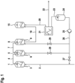
- Figure 1 shows schematically a set-up for preparing multimodal ethylene polymers in a series of three polymerization reactors by a slurry polymerization process.
- the diluent for polymerizing ethylene or copolymerizing ethylene and one or more C 3 -C 12 -1-alkenes in slurry in the first polymerization reactor (1) is fed to the reactor via feeding line (2) while the other components of the reaction mixture like catalyst, ethylene, possible comonomers and polymerization auxiliaries are fed to the reactor via one or more feeding lines (3).
- a slurry of solid polyolefin particle in a liquid medium is formed.
- This slurry is fed via line (4) to the second polymerization reactor (5) where further polymerization occurs.
- Fresh comonomer or further components of the reaction mixture can be fed to reactor (5) via one or more feeding lines (6).
- the slurry of reactor (5) is thereafter fed via line (7) to the third polymerization reactor (8) in which additional polymerization is carried out.
- One or more feeding lines (9) allow supplementary feeding of comonomer or further components of the reaction mixture to reactor (8).
- the slurry of solid polyolefin particle in the liquid medium formed in reactor (8) is continuously transferred via line (10) to collecting vessel (15).
- the slurry is then passed via line (20) to centrifuge (21), where the solid polyolefin particles are separated from the liquid medium.
- the isolated polyolefin particles which after removal of the liquid medium still have from 10 to 30 wt.-% of residual moisture, i.e. of residual liquid medium, are transferred via line (22) to a dryer (not shown) and thereafter to a pelletizing unit (not shown).
- the isolated liquid medium is transferred via line (23) to a further collecting vessel (24) and from there by means of pump (25) via line (26) to the polymerization reactors (1), (5) and/or (8).
- line (26) and its branch-offs are equipped with valves (27), (28) and (29).
- the process of the present disclosure is carried out in a reactor system comprising a polymerization reactor configured to have a content in liquid form, i.e. configured to have a content which can, for example, be a slurry of polymer particle in a liquid medium or a solution of a polymer in a solvent.
- the reactor system further comprises an agitator for agitating the reactor content.
- the reactors of such reactors systems are commonly designated as stirred tank reactors.
- Preferred polymerization reactors are cylindrical polymerization reactors which comprise a cylindrical reactor wall, a bottom reactor head connected to the cylindrical reactor wall at a bottom tangent and a top reactor head connected to the cylindrical reactor wall at a top tangent.
- the cylindrical polymerization reactors have preferably an inner diameter D which corresponds to the inner diameter of the cylindrical reactor wall and a height H which is the distance from the bottom tangent to the top tangent measured along the central axis of the cylindrical polymerization reactor.
- Such cylindrical polymerization reactors have preferably a height/diameter ratio (H/D) from 1.5 to 4 and more preferably a height/diameter ratio (H/D) from 2.5 to 3.5.
- the polymerization reactors have an internal surface in contact with the slurry that has a surface roughness R a of less than 5 ⁇ m, preferably less than 3 ⁇ m, and in particular less than 1.5 ⁇ m determined according to ASME B46.1.
- the agitator of the reactor system of the present disclosure can induce a flow of the reactor content and allows to mix the reactor content.
- the agitator is arranged centrally in the reactor and preferably comprises a motor located on the top reactor head, a rotating shaft which is extending along the reactor's central axis and one or more stages of agitator blades.
- a stage of agitator blades usually comprises several agitator blades.
- Preferred stages of agitator blades comprise from 2 to 4 blades.
- the motor rotates the agitator shaft and the attached agitator blades.
- the rotation of the blades induces primarily a vertical flow of the reactor content in a circular cross-section around the agitator shaft.
- This vertical flow of the reactor content is preferably a downward flow. At the bottom head, this flow changes direction, and flows first outward toward the reactor wall and then back upward to the top, changes direction again and then back to the center of the polymerization reactor.
- the rotation of the agitator also results in a secondary flow pattern of the reactor content in the reactor. This secondary flow is a circular flow in the direction of rotation of the agitator.
- the polymerization reactor is preferably equipped with one or more baffles.
- the reactor system of the process of the present disclosure supports the slurry polymerization of ethylene and optionally one or more comonomers and comprises a polymerization reactor and one or more first heat exchangers located outside the polymerization reactor.
- the reactor system for carrying out the process of the present disclosure comprises one or more first heat exchangers located outside the polymerization reactor for cooling or heating the reactor content.
- the heat of polymerization is removed from the polymerization reactor by withdrawing slurry from the polymerization reactor, cooling the slurry in the one or more first heat exchangers and returning the cooled slurry to the polymerization reactor.
- the one or more first heat exchangers can be any of those normally employed for the fluids described herein at the temperature and pressures involved, e.g., the heat exchangers can be selected from double pipe, shell & tube, plate, plate & shell and spiral heat exchangers.
- the first heat exchangers are double pipe heat exchangers.
- Such are basically long, jacketed pipes, which are usually from about 100 m to 600 m long.
- the inner diameter of the pipes is usually in the range of from about 150 mm to 400 mm.
- the double pipe heat exchangers are composed of individual jacketed segments. These segments are preferably flanged together, either directly or separated by a bend. Preferred bends are 180° bend bends.
- the straight individual segments have a length of from 6 m to 12 m.
- Each double pipe heat exchangers is preferably composed of from 4 to 50, more preferably from 5 to 40 and in particular from 10 to 35 individual jacketed segments
- the flows of the reactor content and the flows of the tempering medium through the jackets of the double pipe heat exchangers may be co-current, counter-current or a combination of co-current/counter-current.
- the flows in the first heat exchangers are a combination of co-current/counter-current.
- the first heat exchangers are double pipe heat exchangers which have an internal surface in contact with the slurry that has a surface roughness R a of less than 5 ⁇ m, preferably less than 3 ⁇ m, and in particular less than 1.5 ⁇ m determined according to ASME B46.1. Designing the double pipe heat exchangers with an internal surface having a surface roughness R a of less than 5 ⁇ m minimizes the build-up of wall layers.
- the surface roughness R a as defined in the present disclosure can, for example be realized by polishing, such as mechanical polishing or electropolishing.
- the reactor system has one first heat exchanger located outside the polymerization reactor.
- the reactor system may also have two, three, four or more first heat exchangers located outside the polymerization reactor.
- the reactor system has two or three first heat exchangers.
- the reactor system for carrying out the process of the present disclosure further comprises one or more circulation pumps for withdrawing the reactor content from the polymerization reactor and circulating the reactor content through the one or more first heat exchangers.
- the tempering medium is preferably circulated by means of circulation pumps which provide a substantially constant flow rate of the tempering medium at the outlets of the circulation pumps.
- the one or more circulation pumps are preferably arranged upstream of the one or more first heat exchangers, i.e. between the outlet of the polymerization reactor where the withdrawn reactor content leaves the polymerization reactor and the one or more first heat exchangers.
- Preferred circulation pumps are centrifugal pumps having an semi-open impeller made from electro-polished stainless steel.
- the tempering medium for cooling or heating the one or more first heat exchangers is circulated in a closed loop.
- the reactor system comprises more than one first heat exchangers, preferably all first heat exchangers of the reactor system are operated in parallel in one closed loop of the circulating tempering medium.
- the one or more first heat exchangers located outside the polymerization reactor serve as well for cooling the content of the polymerization reactor as for heating the content of the polymerization reactor.
- the first heat exchangers have accordingly to be provided with a cooling medium when cooling the content of the polymerization reactor or the first heat exchangers have to be provided with a heating medium when heating the content of the polymerization reactor.
- both tasks are performed by a tempering medium which serves for cooling the one or more first heat exchangers and which serves for heating the one or more first heat exchangers.
- the closed loop of the tempering medium is equipped with two further heat exchangers, a second heat exchanger for cooling the tempering medium and a third heat exchangers for heating the tempering medium.
- Cooling the tempering medium i.e. using the tempering medium as coolant, takes place during the polymerization of ethylene or the copolymerization of ethylene and one or more C 3 -C 12 -1-alkenes in the polymerization reactor for removing the heat of polymerization.
- the second heat exchanger for cooling the tempering medium is cooled by a coolant which is preferably water.
- the coolant is provided through a coolant feed line, passed through the second heat exchanger and is then withdrawn through a coolant exit line.
- the second heat exchanger for cooling the tempering medium is a plate heat exchanger.
- the second heat exchanger is dived in a multitude of plate heat exchangers operating in parallel, for example a battery of two, three, four, five, six, seven, eight, nine or ten plate heat exchangers operating in parallel.
- the second heat exchanger for cooling the tempering medium is a cooling tower such as for example an atmospheric cooling tower.
- the temperature of the circulated tempering medium can be maintained by adjusting the flow rate of the coolant through the second heat exchanger by means of a control valve located in the coolant feed line or preferably in the coolant exit line.
- the controlling of the temperature of the circulated tempering medium occurs by splitting the stream of the tempering medium conveyed to the second heat exchanger into two portions. One portion passes the second heat exchanger for being cooled by the coolant, while the second portion bypasses the second heat exchanger and directly returns to the inlet side of the circulation pump circulating the tempering medium.
- the flow rate of the tempering medium through the bypass is preferably adjusted by a control valve located in the bypass line. Varying the opening of the control valve varies the ratio of the portion of the tempering medium running through the second heat exchanger to the portion bypassing the second heat exchanger and accordingly varies the temperature of the combined tempering medium after bringing these two portions together again.
- Heating the tempering medium i.e. using the tempering medium as heating medium for the content of the polymerization reactor, takes place, for example, in the start-up of the polymerization or during cleaning of the reactor system.
- the third heat exchanger for heating the tempering medium is heated by a heating medium which is preferably steam.
- the heating medium is then provided through a heating medium feed line, passed through the third heat exchanger and is then withdrawn through a heating medium exit line.
- the third heat exchanger for heating the tempering medium is a shell and tube heat exchanger.
- all first heat exchangers are cooled or heated by a tempering medium which is circulated in one closed loop system and all first heat exchangers are operated in parallel in the closed loop of the circulating tempering medium which is cooled by one second heat exchanger.
- the slurry in the polymerization reactor is not only cooled or heated in one or more first heat exchangers located outside the polymerization reactor but also by a tempering jacket at the outside of the polymerization reactor.
- the tempering jacket is also tempered by the tempering medium cooling or heating the one or more first heat exchangers used for cooling or heating the reactor content.
- the tempering jacket preferably consists of a series of half-pipes attached to the outside of the polymerization reactor. It is further preferred that the first heat exchangers and the tempering jacket at the outside of the polymerization reactor are operated in parallel in the closed loop of the circulating tempering medium.
- each of the reactor reactors is equipped at the reactor outside with a tempering jacket. It is especially preferred that all first heat exchangers and all cooling jackets are operated in parallel in the closed loop of the circulating tempering medium.
- the polymerization reactor is filled with a slurry of ethylene polymer particles in a liquid medium comprising a hydrocarbon diluent; and the slurry is cooled by withdrawing slurry from the polymerization reactor, cooling the slurry in the one or more first heat exchangers and returning the cooled slurry to the polymerization reactor.
- the temperature of the tempering medium cooling the one or more first heat exchangers is in the range from 20°C to 50°C, preferably from 25°C to 45°C, and more preferably from 29°C to 40°C, and the tempering medium is cooled in the second heat exchanger by a coolant having a temperature from -20° to 45°C, preferably from 15°C to 40°C, and more preferably from 20°C to 36°C.
- the process for polymerizing ethylene or copolymerizing ethylene and one or more C 3 -C 12 -1-alkenes comprises a cleaning step for cleaning the polymerization reactor, for cleaning the one or more first heat exchangers or for cleaning the polymerization reactor and the one or more first heat exchangers.
- the cleaning step preferably comprises the sub-steps of terminating the polymerization, introducing a hydrocarbon solvent into reactor system thereby forming a cleaning fill, heating the cleaning fill and circulating the cleaning fill within the reactor system with operating the agitator within the polymerization reactor, discharging the cleaning fill from the reactor system and resuming the polymerization of ethylene or copolymerization of ethylene and one or more C 3 -C 12 -1 alkenes in the reactor system.
- the termination of the polymerization of ethylene or the copolymerization of ethylene and one or more C 3 -C 12 -1-alkenes in the reactor system preferably occurs by terminating all feed streams to the reactor system or the combination of double pipe reactor systems while preferably continuing with the operation of the circulation pumps or the circulation pumps. Terminating the feed streams means that no longer ethylene, comonomer, catalyst, hydrogen and hydrocarbon diluent are fed to the reactor system. Thereafter, the slurry of ethylene polymer particles in the liquid medium is discharged from the reactor system until the reactor system is empty.
- a preferred method for discharging a slurry of ethylene polymer particles in a liquid medium from a multi-reactor slurry polymerization system is for example disclosed in WO 2018/127472 A1 .
- the reactor system is preferably flushed with a hydrocarbon for removing ethylene polymer particles which may remain in the reactor system after the slurry has been discharged.
- the hydrocarbon for flushing the reactor system is preferably the hydrocarbon used as diluent in the polymerization.
- the hydrocarbon for removing remaining ethylene polymer particles is introduced into the reactor system and then circulated by the one or more circulation pumps through the one or more first heat exchangers, e.g. for from 10 min to 3 hours. Thereafter, the agitator of the polymerization reactor is preferably stopped and the circulation pumps are operated for from 1 hour to 12 hours, more preferably for from 1.5 hours to 8 hours and in particular for from 2 hours to 4 hours.
- the circulation pumps are preferably stopped and the content of the reactor is discharged, preferably through a bottom outlet of the polymerization reactor.
- the agitator of the polymerization reactor is restarted while still a part of the hydrocarbon used for flushing the reactor system is left in the polymerization reactor.
- at least the bottom part of the polymerization reactor is flushed a second time with hydrocarbon for removing still remaining ethylene polymer particles.
- a hydrocarbon solvent is introduced into the emptied reactor system thereby forming a cleaning fill within the reactor system.
- the hydrocarbon solvent for cleaning the reactor system is preferably the hydrocarbon diluent used in the polymerization.
- the hydrocarbon solvent is preferably introduced into the emptied reactor system until a liquid level of the cleaning fill within the polymerization reactor is reached which is at least as high as the liquid level of the slurry within the polymerization reactor during polymerization.
- the reactor system is completely filled with the hydrocarbon solvent.
- the cleaning fill within the reactor system is preferably heated to a temperatures from 100°C to 180°C, preferably from 110°C to 170°C and more preferably from 120°C to 160°C, while the agitator within the polymerization reactor is operated.
- the heating occurs preferably by withdrawing parts of the cleaning fill from the polymerization reactor, heating the withdrawn parts of the cleaning fill in the one or more first heat exchangers and returning the heated parts of the cleaning fill to the polymerization reactor.
- the tempering medium is preferably heated in the third heat exchanger by providing the third heat exchanger with a heating medium having a temperature from 150°C to 250°C, preferably from 170°C to 230°C and more preferably from 180°C to 210°C
- the heating medium for heating the third heat exchanger is preferably steam having a pressure from 0.6 MPa to 1.5 MPa, more preferably having a pressure from 0.7 MPa to 1.1 MPa.
- the cleaning fill is not only heated by passing parts of the cleaning fill through the heated one or more first heat exchangers but also by heating the tempering jacket at the outside of the polymerization reactor.
- the heated cleaning fill is preferably maintained within the reactor system at the temperature from 100°C to 180°C, preferably from 110°C to 170°C and more preferably from 120°C to 160°C for from 4 hours to 120 hours, preferably from 10 hours to 80 hours and more preferably from 15 hours to 50 hours with continued circulation of the cleaning fill through the one or more first heat exchangers and continued operation of the agitator.
- the cleaning fill is subsequently discharged from the reactor system until the reactor system is empty. Thereafter, the polymerization of ethylene or the copolymerization of ethylene and one or more C 3 -C 12 -1 alkenes is resumed in the reactor system.
- the contents of the polymerization reactor and of the one or more first heat exchangers may be discharged together through one outlet of the reactor system.
- the content of the polymerization reactor and the contents of the one or more first heat exchangers are discharged separately through two or more outlets of the reactor system.
- the circulation of the cleaning fill from the polymerization reactor through the one or more first heat exchangers is terminated and the contents of the one or more first heat exchangers and of the polymerization reactor are subsequently discharged through two or more outlets of the reactor system.
- the introduction of the hydrocarbon solvent into the reactor system is terminated after a cleaning fill within the reactor system has been formed, and thereafter the maintenance of the cleaning fill within the reactor system at the temperature from 100°C to 180°C and the discharge of the cleaning fill from the reactor system occur without introduction of additional hydrocarbon solvent.
- the introduction of the hydrocarbon solvent into the reactor system is not terminated after a cleaning fill within the reactor system has been formed and the liquid level of the cleaning fill within the polymerization reactor is maintained by discharging cleaning fill from the reactor system.
- Continuously introducing hydrocarbon solvent and continuously withdrawing cleaning fill from the reactor system provides that a viscosity increases of the cleaning fill within the reactor system by the dissolution of the oligomeric or polymeric walls layers is less pronounced and that a saturation of the cleaning fill with dissolved walls layers does not take place or at least is reached later.
- the cleaning fill which is discharged from the reactor system is transferred into an agitated evaporation vessel which is configured to allow withdrawal of hydrocarbon solvent by evaporation from a liquid medium comprising such hydrocarbon solvent.
- the discharge of the cleaning fill from the reactor system into the agitated distillation vessel occurs preferably by a pressure difference between the cleaning fill within the reactor system and the agitated distillation vessel.
- the depressurization of the hot cleaning fill occurs while entering the evaporation vessel resulting in a considerable temperature drop combined with an evaporation of a significant amount of hydrocarbon.
- the evaporation vessel is first filled with cleaning fill discharged from the reactor system and thereafter the evaporation of the hydrocarbon solvent is started.
- the evaporation is preferably continued until a concentrated mixture of the previously solved oligomeric and polymeric materials and remaining hydrocarbon solvent is formed. Usually at least a part of the previously solved oligomeric and polymeric materials has precipitated.
- the evaporation vessel can be filled again with cleaning fill discharged from the reactor system.
- cleaning fill discharged from the reactor system which can no longer be fed into the agitated evaporation vessel because the evaporation vessel is completely filled, is fed into a second agitated evaporation vessel instead of interrupting the discharge until the agitated evaporation vessel is emptied again.
- Figure 2 shows schematically a set-up of a reactor system for carrying out the process of the present disclosure for polymerizing ethylene or copolymerizing ethylene and one or more C 3 -C 12 -1-alkenes.
- Polymerization reactor (100) includes an agitator (101) for agitating the contents of the reactor.
- the agitator (101) comprises a motor (102), a rotating shaft (103) which is substantially vertically installed centrally into reactor (100), and at least one impeller (104).
- the polymerization reactor (100) is equipped with a tempering jacket (105) on the outside surface of the reactor (100) through which a tempering medium flows.
- Reactor content is withdrawn from polymerization reactor (100) through line (106) to circulation pump (107), which then pumps the reactor content through line (108) to the first heat exchanger (109).
- the tempered reactor content which has passed the first heat exchanger (109) flows back to polymerization reactor (100) through line (110).
- the tempering medium for tempering the first heat exchanger (109) comes through line (111).
- the components of the reaction mixture such as catalyst components, ethylene, possible comonomers, hydrogen and the hydrocarbon diluent are fed to the reactor via one or more feeding lines (112).
- slurry is withdrawn from polymerization reactor (100) and the first heat exchanger (109) operates as cooler. Slurry is further routed to a downstream reactor or to product recovery through line (113).
- valves (163), (165), (180) and (181) are closed.
- the cooled tempering medium for cooling the first heat exchanger (109) comes from the second heat exchanger (120).
- the cooled tempering medium leaving the second heat exchanger (120) through line (130) is circulated by a second circulation pump (121) through lines (122) and (123), valve (124) and line (111) to the first heat exchanger (109), and then through valves (125) and (126), control valve (127) and lines (128) and (129) back to the second heat exchanger (120).
- the tempering jacket (105) of the polymerization reactor (100) is cooled by the tempering medium.
- the second circulation pump (121) circulates the cooled tempering medium leaving the second heat exchanger (120) through line (130) through lines (122) and (131), valve (132) and line (133) to the tempering jacket (105), and then through line (134), valve (135), control valve (136) and line (129) back to the second heat exchanger (120).
- temperature transducer (140) produces a temperature signal (141) which is representative of the temperature of polymerization reactor (100).
- Temperature controller (142) receives the temperature signal (141) along with a setpoint (SP) which is representative of the desired temperature for the polymerization reactor (100).
- temperature controller (142) provides output signals (143) and (144) which are responsive to the difference between temperature signal (141) and the setpoint for the reactor temperature.
- Control valves (127) and (136) which are controlling the flows of the tempering medium from the first heat exchanger (109) and the tempering jacket (105) to the second heat exchanger (120) are manipulated in response to signals (143) and (144).
- the tempering medium is cooled in the second heat exchanger (120) using a coolant entering the second heat exchanger (120) through line (150) and leaving the second heat exchanger (120) through line (151).
- a part of the tempering medium conveyed through line (129) does not pass the second heat exchanger (120) but bypasses the second heat exchanger (120) through line (152).
- the flow of the tempering medium bypassing the second heat exchanger (120) is adjusted by control valve (153).
- Temperature transducer (154) produces a temperature signal (155), which is representative of the temperature of the combined tempering medium after merging the part of the tempering medium passing the second heat exchanger (120) and the part of the tempering medium bypassing the second heat exchanger (120) through line (152).
- Temperature controller (156) receives the temperature signal (155) along with a setpoint (SP) which is representative of the desired temperature for the tempering medium entering the second circulation pump (121).
- temperature controller (156) provides output signal (157) which is responsive to the difference between temperature signal (155) and the setpoint for the temperature of the tempering medium flowing in line (130).
- Control valve (153) is manipulated in response to signal (157).
- the first heat exchanger (109) is operated as heater for heating the parts of the reactor content which are withdrawn from the polymerization reactor (100) and circulated through the first heat exchanger (109).
- valves (124), (126), (132) and (135) are closed and the tempering medium for heating the first heat exchanger (109) comes from the third heat exchanger (160).
- the tempering medium is circulated by a third circulation pump (161) through the third heat exchanger (160), line (162), valve (163) and line (111) to the first heat exchanger (109), and then through valve (125), line (164), valve (165) and line (166) back to the third circulation pump (161).
- the tempering medium is heated in the third heat exchanger (160), preferably using medium pressure steam entering the third heat exchanger (160) through line (170).
- the medium pressure steam comes through line (171) to control valve (172) which adjusts the flow of the medium pressure steam.
- the medium pressure steam then flows through line (170) into the third heat exchanger (160), through the third heat exchanger (160), and then exits the third heat exchanger (160) through line (173).
- temperature transducer (174) produces a temperature signal (175), which is representative of the temperature of the tempering medium leaving the third heat exchanger (160) through line (162).
- Temperature controller (176) receives the temperature signal (175) along with a setpoint (SP) which is representative of the desired temperature for the tempering medium flowing in line (162). In response to temperature signal (175), temperature controller (176) provides output signal (177) which is responsive to the difference between temperature signal (175) and the setpoint for the temperature of the tempering medium flowing in line (162). Control valve (172) is manipulated in response to signal (177).
- SP setpoint
- the tempering medium is then circulated by the third circulation pump (161) through the third heat exchanger (160), line (162), valve (180) and line (133) to the tempering jacket (105), and then through line (133), valve (181), line (164), valve (165) and line (166) back to the third circulation pump (161).
- valves (190) and (191) are opened and the content of the first heat exchanger (109) is discharged through line (108), circulation pump (107), valve (190), lines (192) and (193), and valve (191) into evaporation vessel (194).
- valve (190) is closed and valve (195) is opened and the content of the polymerization reactor (100) is discharged through valve (195), lines (196) and (193), and valve (191) into evaporation vessel (194).
- the evaporation vessel (194) includes an agitator (197) for agitating the contents of the reactor.
- the agitator (197) comprises a motor (198), a rotating shaft (199) which is substantially vertically installed centrally into the evaporation vessel (194), and at least one impeller (200).
- evaporated hydrocarbon solvent is withdrawn through line (201) to the off-gas system (not shown).
- a concentrated mixture of previously solved oligomeric and polymeric materials and remaining hydrocarbon solvent is withdrawn through line (202) and discarded.
- the process of the present disclosure allows to clean the reactor system with hot hydrocarbons in a fast and economical manner, in particular permitting a fast transition from cooling the first heat exchangers and tempering jackets to heating the first heat exchangers and tempering jackets, and vice versa.
- the process is easy to control and it is not needed to replace defective external heat exchangers or polymerization reactor tempering jackets from time to time.
- the process nonetheless allows to prepare the ethylene polymers with the targeted combination of polymer properties without operational problems.
- Ethylene polymers were continuously prepared in a commercially operated series of three reactor systems comprising each a polymerization reactor as shown in Figure 1 .
- Each of the polymerization reactors were part of a reactor system further comprising two parallel first heat exchangers located outside the polymerization reactor for removing the heat of polymerization. All first heat exchangers were composed of straight jacketed segments having each a length of 12 m which segments were flanged together.
- the polymerization reactors were further equipped with tempering jackets. The first heat exchangers and the tempering jackets of the polymerization reactors were all cooled by a coolant which circulated in a closed loop and the coolant was cooled in a second heat exchanger.
- polymerizations of ethylene and 1-butene as comonomer were carried out in slurry in the presence of Ziegler-type catalysts at reactor temperatures in the range from 65°C to 85°C and reactor pressures from 0.2 MPa to 1.3 MPa preparing a variety of different polyethylene grades. Depending on the grades, the production rate varied in the range from 30 to 41 t/h.
- Ethylene polymers were continuously prepared in a commercially operated series of three reactor systems comprising each a polymerization reactor as shown in Figure 1 .
- Each of the polymerization reactors were part of a reactor system as shown in Figure 2 , however comprising two parallel first heat exchangers located outside the polymerization reactor instead of one as shown in Figure 2 for removing the heat of polymerization.
- All first heat exchangers were composed of straight jacketed segments having each a length of 12 m which segments were flanged together.
- the polymerization reactors were further equipped with tempering jackets.
- the first heat exchangers and the tempering jackets of the polymerization reactors were all cooled by a tempering medium which circulated in a closed loop.
- the tempering medium was cooled in a second heat exchanger.
- polymerizations of ethylene and 1-butene as comonomer were carried out in slurry in the presence of Ziegler-type catalysts at reactor temperatures in the range from 65°C to 85°C and reactor pressures from 0.2 MPa to 1.3 MPa preparing a variety of different polyethylene grades. Depending on the grades, the production rate varied in the range from 30 to 41 t/h.
Landscapes
- Chemical & Material Sciences (AREA)
- Health & Medical Sciences (AREA)
- Chemical Kinetics & Catalysis (AREA)
- Medicinal Chemistry (AREA)
- Polymers & Plastics (AREA)
- Organic Chemistry (AREA)
- Polymerisation Methods In General (AREA)
- Addition Polymer Or Copolymer, Post-Treatments, Or Chemical Modifications (AREA)
Claims (15)
- Procédé de polymérisation d'éthylène ou de copolymérisation d'éthylène et d'un ou de plusieurs 1-alcènes en C3-C12 dans une polymérisation en suspension à des températures de 40 à 150 °C et à des pressions de 0,1 à 5 MPa en présence d'un catalyseur de polymérisation,le procédé étant mis en œuvre dans un système de réacteur comprenant- un réacteur de polymérisation conçu pour présenter un contenu sous forme liquide ;- un agitateur destiné à agiter le contenu du réacteur ;- un ou plusieurs premiers échangeurs de chaleur situés à l'extérieur du réacteur de polymérisation et destinés à refroidir ou à chauffer le contenu du réacteur ;- une ou plusieurs pompes de circulation destinées à soustraire le contenu du réacteur à partir du réacteur de polymérisation et à faire circuler le contenu du réacteur à travers ledit un ou lesdits plusieurs premiers échangeurs de chaleur ; et- une boucle fermée d'un agent de thermorégulation destiné à refroidir ou à chauffer ledit un ou lesdits plusieurs premiers échangeurs de chaleur, laquelle boucle fermée est équipée d'un deuxième échangeur de chaleur destiné à refroidir l'agent de thermorégulation et équipée d'un troisième échangeur de chaleur destiné à chauffer l'agent de thermorégulation, etdans lequel, lors de la polymérisation de l'éthylène ou de la copolymérisation de l'éthylène et dudit un ou desdits plusieurs 1-alcènes en C3-C12,- le réacteur de polymérisation est rempli d'une suspension de particules de polymère d'éthylène dans un milieu liquide comprenant un diluant hydrocarboné ;- la suspension est refroidie par soustraction de la suspension à partir du réacteur de polymérisation, refroidissement de la suspension dans ledit un ou lesdits plusieurs premiers échangeurs de chaleur et renvoi de la suspension refroidie au réacteur de polymérisation ;- la température de l'agent de thermorégulation refroidissant ledit un ou lesdits plusieurs premiers échangeurs de chaleur est située dans la plage de 20 °C à 50 °C ; et- l'agent de thermorégulation est refroidi dans le deuxième échangeur de chaleur par un fluide de refroidissement présentant une température de -20 ° à 45 °C.
- Procédé selon la revendication 1, dans lequel le système de réacteur fait partie d'une série de deux ou trois systèmes de réacteur ou plus, comprenant chacun un réacteur de polymérisation et un ou plusieurs premiers échangeurs de chaleur situés à l'extérieur du réacteur de polymérisation et destinés à refroidir ou à chauffer le contenu du réacteur.
- Procédé selon la revendication 1 ou 2, dans lequel les premiers échangeurs de chaleur sont des échangeurs de chaleur à double tuyau, présentant de préférence une rugosité de surface Ra inférieure à 5 µm, déterminée selon la norme ASME B46.1.
- Procédé selon l'une quelconque des revendications 1 à 3, dans lequel les réacteurs de polymérisation sont en outre équipés à l'extérieur du réacteur par des chemises de thermorégulation.
- Procédé selon la revendication 4, dans lequel les chemises de thermorégulation sont constituées d'une série de demi-tuyaux fixés à l'extérieur des réacteurs de polymérisation.
- Procédé selon la revendication 4 ou 5, dans lequel l'agent de thermorégulation destiné à refroidir ou à chauffer la chemise de thermorégulation est l'agent de thermorégulation destiné à refroidir ou à chauffer ledit un ou lesdits plusieurs premiers échangeurs de chaleur.
- Procédé selon l'une quelconque des revendications 1 à 6, comprenant une étape de nettoyage destinée à nettoyer le réacteur de polymérisation, à nettoyer ledit un ou lesdits plusieurs premiers échangeurs de chaleur ou à nettoyer le réacteur de polymérisation et ledit un ou lesdits plusieurs premiers échangeurs de chaleur, l'étape de nettoyage comprenant les sous-étapes dearrêt de la polymérisation de l'éthylène ou de la copolymérisation de l'éthylène et d'un ou de plusieurs 1-alcènes en C3-C12 dans le système de réacteur et évacuation de la suspension de particules de polymère d'éthylène à partir du système de réacteur jusqu'à ce que le système de réacteur soit vide ;introduction d'un solvant hydrocarboné dans le système de réacteur vidé, formant ainsi une charge de nettoyage à l'intérieur du système de réacteur ;chauffage de la charge de nettoyage à l'intérieur du système de réacteur à une température de 100 à 180 °C,- l'agitateur à l'intérieur du réacteur de polymérisation fonctionnant ;- la charge de nettoyage étant chauffée par soustraction de parties de la charge de nettoyage à partir du réacteur de polymérisation, chauffage des parties de la charge de nettoyage dans ledit un ou lesdits plusieurs premiers échangeurs de chaleur et renvoi des parties chauffées de la charge de nettoyage au réacteur de polymérisation ; et- l'agent de thermorégulation étant chauffé dans le troisième échangeur de chaleur par fourniture, au troisième échangeur de chaleur, d'un milieu chauffant présentant une température de 150 °C à 250 °C ;maintien de la charge de nettoyage à l'intérieur du système de réacteur à la température de 100 °C à 180 °C pendant 4 à 120 heures avec une circulation continue de la charge de nettoyage à travers ledit un ou lesdits plusieurs premiers échangeurs de chaleur et un fonctionnement constant de l'agitateur ;évacuation de la charge de nettoyage à partir du système de réacteur jusqu'à ce que le système de réacteur soit vide ; etreprise de la polymérisation de l'éthylène ou de la copolymérisation de l'éthylène et d'un ou de plusieurs 1-alcènes en C3-C12 dans le système de réacteur.
- Procédé selon la revendication 7, dans lequel, après l'évacuation de la suspension de particules de polymère d'éthylène à partir du système de réacteur et avant l'introduction de la charge de nettoyage dans le système de réacteur, une sous-étape de rinçage du système de réacteur à l'aide d'un diluant hydrocarboné est mise en œuvre.
- Procédé selon la revendication 7 ou 8, dans lequel le solvant hydrocarboné est introduit dans le système de réacteur vidé jusqu'à ce qu'un niveau de liquide de la charge de nettoyage à l'intérieur du réacteur de polymérisation soit au moins aussi élevé que le niveau de liquide de la suspension à l'intérieur du réacteur de polymérisation pendant la polymérisation.
- Procédé selon l'une quelconque des revendications 7 à 9, dans lequel l'introduction du solvent hydrocarboné dans le système de réacteur est arrêtée après la formation d'une charge de nettoyage à l'intérieur du système de réacteur et ensuite le maintien de la charge de nettoyage à l'intérieur du système de réacteur à la température de 100 °C à 180 °C et l'évacuation de la charge de nettoyage à partir du système de réacteur se produisent sans introduction de solvant hydrocarboné supplémentaire.
- Procédé selon l'une quelconque des revendications 7 à 9, dans lequel, pendant le maintien de la charge de nettoyage à l'intérieur du système de réacteur à une température de 100 °C à 180 °C, un solvant hydrocarboné est introduit en continu dans le système de réacteur et la charge de nettoyage est évacuée en continu à partir du système de réacteur.
- Procédé selon l'une quelconque des revendications 7 à 11, dans lequel, pour la vidange du système de réacteur avant la reprise de la polymérisation, la circulation de la charge de nettoyage depuis le réacteur de polymérisation à travers ledit un ou lesdits plusieurs premiers échangeurs de chaleur est arrêtée et les contenus dudit un ou desdits plusieurs premiers échangeurs de chaleur et du réacteur de polymérisation sont ensuite évacués.
- Procédé selon l'une quelconque des revendications 7 à 12, dans lequel la charge de nettoyage évacuée à partir du système de réacteur est transférée dans une cuve d'évaporation agitée qui est conçue pour permettre la soustraction de solvant hydrocarboné par évaporation à partir d'un milieu liquide comprenant un tel solvant hydrocarboné.
- Procédé selon la revendication 13, dans lequel l'évacuation de la charge de nettoyage à partir du système de réacteur dans le récipient de distillation agité se produit par une différence de pression entre la charge de nettoyage à l'intérieur du système de réacteur et le récipient de distillation agité.
- Procédé selon l'une quelconque des revendications 2 à 14, dans lequel les polymères d'éthylène obtenus sont des polymères bimodaux ou multimodaux d'éthylène.
Applications Claiming Priority (2)
| Application Number | Priority Date | Filing Date | Title |
|---|---|---|---|
| EP21216856 | 2021-12-22 | ||
| PCT/EP2022/086851 WO2023118046A1 (fr) | 2021-12-22 | 2022-12-20 | Procédé de préparation de polymères d'éthylène dans une polymérisation en suspension |
Publications (2)
| Publication Number | Publication Date |
|---|---|
| EP4416193A1 EP4416193A1 (fr) | 2024-08-21 |
| EP4416193B1 true EP4416193B1 (fr) | 2025-03-19 |
Family
ID=79927568
Family Applications (1)
| Application Number | Title | Priority Date | Filing Date |
|---|---|---|---|
| EP22844040.0A Active EP4416193B1 (fr) | 2021-12-22 | 2022-12-20 | Procédé de préparation de polymères d'éthylène dans une polymérisation en suspension |
Country Status (6)
| Country | Link |
|---|---|
| US (1) | US20250051497A1 (fr) |
| EP (1) | EP4416193B1 (fr) |
| JP (1) | JP7672581B2 (fr) |
| KR (1) | KR102809892B1 (fr) |
| CN (1) | CN118382647A (fr) |
| WO (1) | WO2023118046A1 (fr) |
Families Citing this family (2)
| Publication number | Priority date | Publication date | Assignee | Title |
|---|---|---|---|---|
| WO2025077838A1 (fr) * | 2023-10-11 | 2025-04-17 | 中国石油化工股份有限公司 | Échangeur de chaleur, réacteur et son utilisation, et procédé de polymérisation d'oléfines |
| EP4563604A1 (fr) * | 2023-11-30 | 2025-06-04 | Basell Polyolefine GmbH | Procédé de préparation de polymères d'éthylène dans une polymérisation en suspension avec interruption |
Family Cites Families (13)
| Publication number | Priority date | Publication date | Assignee | Title |
|---|---|---|---|---|
| DE19742507A1 (de) | 1997-09-26 | 1999-04-01 | Hostalen Polyethylen Gmbh | Polyolefin-Suspensionspolymerisation |
| JP2009120588A (ja) * | 2007-10-23 | 2009-06-04 | Mitsubishi Chemicals Corp | エチレン低重合体の製造方法及び1−ヘキセンの製造方法 |
| CN105348417B (zh) * | 2010-01-14 | 2019-03-01 | 埃克森美孚化学专利公司 | 连续溶液聚合的方法和设备 |
| WO2012028591A1 (fr) | 2010-08-31 | 2012-03-08 | Basell Polyolefine Gmbh | Procédé de préparation d'un polymère polyoléfinique avec dépôt de cire amélioré |
| WO2013186299A1 (fr) * | 2012-06-14 | 2013-12-19 | Basell Polyolefine Gmbh | Procédé de refroidissement d'un réacteur en phase gazeuse pour la polymérisation d'oléfines |
| US10646845B2 (en) * | 2013-07-03 | 2020-05-12 | Chevron Phillips Chemical Company Lp | Cooling between multiple polyolefin polymerization reactors |
| EP3145632B1 (fr) * | 2014-05-20 | 2017-10-04 | Basell Polyolefine GmbH | Procédé de polymérisation d'éthylène en suspension a performance améliorée de la pompe |
| EP3161016B1 (fr) * | 2014-06-25 | 2017-10-04 | Basell Polyolefine GmbH | Procédé de polymérisation d'éthylène présentant une meilleure performance d'échangeur de chaleur |
| US10047176B2 (en) * | 2014-08-14 | 2018-08-14 | Basell Polyolefine Gmbh | Multi-reactor slurry polymerization processes with high ethylene purity |
| FR3061034B1 (fr) * | 2016-12-22 | 2019-05-31 | IFP Energies Nouvelles | Procede d'oligomerisation d'olefines mettant en œuvre un dispositif de nettoyage |
| CN110099929B (zh) | 2017-01-03 | 2020-05-26 | 巴塞尔聚烯烃股份有限公司 | 多反应器浆料聚合方法 |
| SG11202011186PA (en) * | 2018-06-21 | 2020-12-30 | Basell Polyolefine Gmbh | Suspension process for preparing ethylene copolymers in a reactor cascade |
| JP7302102B2 (ja) * | 2020-03-24 | 2023-07-03 | バーゼル・ポリオレフィン・ゲーエムベーハー | 懸濁媒質のワークアップを含むエチレン重合体の製造のための懸濁プロセス |
-
2022
- 2022-12-20 KR KR1020247020720A patent/KR102809892B1/ko active Active
- 2022-12-20 JP JP2024534605A patent/JP7672581B2/ja active Active
- 2022-12-20 US US18/720,775 patent/US20250051497A1/en active Pending
- 2022-12-20 EP EP22844040.0A patent/EP4416193B1/fr active Active
- 2022-12-20 CN CN202280081824.9A patent/CN118382647A/zh active Pending
- 2022-12-20 WO PCT/EP2022/086851 patent/WO2023118046A1/fr not_active Ceased
Also Published As
| Publication number | Publication date |
|---|---|
| CN118382647A (zh) | 2024-07-23 |
| JP7672581B2 (ja) | 2025-05-07 |
| US20250051497A1 (en) | 2025-02-13 |
| EP4416193A1 (fr) | 2024-08-21 |
| WO2023118046A1 (fr) | 2023-06-29 |
| KR20240108512A (ko) | 2024-07-09 |
| JP2024545179A (ja) | 2024-12-05 |
| KR102809892B1 (ko) | 2025-05-19 |
Similar Documents
| Publication | Publication Date | Title |
|---|---|---|
| JP4683805B2 (ja) | ポリオレフィンの製造法 | |
| US5241023A (en) | Process and device for the gas phase polymerization of alpha-olefins | |
| EP4416193B1 (fr) | Procédé de préparation de polymères d'éthylène dans une polymérisation en suspension | |
| US8138282B2 (en) | Loop reactor suitable for olefin polymerization with improved product removal means | |
| EP1720914A2 (fr) | Multireacteur en boucle pour la polymerisation d'olefines | |
| WO2020227251A1 (fr) | Système et procédé de chauffage rapide de réservoir de vidange | |
| EA011774B1 (ru) | Способ полимеризации в суспензионной фазе и реактор для его осуществления | |
| EP2277621B1 (fr) | Procédé de polymérisation en dispersion | |
| EA009911B1 (ru) | Способ полимеризации олефинов | |
| EP3532507B1 (fr) | Procédé de polymérisation en suspension à réacteurs multiples | |
| TWI392688B (zh) | 泥漿相之聚合方法(三) | |
| EP4563604A1 (fr) | Procédé de préparation de polymères d'éthylène dans une polymérisation en suspension avec interruption | |
| JP5913629B2 (ja) | 生成分配の制御を改良したループリアクター | |
| EA016208B1 (ru) | Многоконтурный реактор для полимеризации олефинов | |
| CN101495224A (zh) | 用于聚合的环流型反应器 |
Legal Events
| Date | Code | Title | Description |
|---|---|---|---|
| STAA | Information on the status of an ep patent application or granted ep patent |
Free format text: STATUS: UNKNOWN |
|
| STAA | Information on the status of an ep patent application or granted ep patent |
Free format text: STATUS: THE INTERNATIONAL PUBLICATION HAS BEEN MADE |
|
| PUAI | Public reference made under article 153(3) epc to a published international application that has entered the european phase |
Free format text: ORIGINAL CODE: 0009012 |
|
| STAA | Information on the status of an ep patent application or granted ep patent |
Free format text: STATUS: REQUEST FOR EXAMINATION WAS MADE |
|
| 17P | Request for examination filed |
Effective date: 20240514 |
|
| AK | Designated contracting states |
Kind code of ref document: A1 Designated state(s): AL AT BE BG CH CY CZ DE DK EE ES FI FR GB GR HR HU IE IS IT LI LT LU LV MC ME MK MT NL NO PL PT RO RS SE SI SK SM TR |
|
| GRAP | Despatch of communication of intention to grant a patent |
Free format text: ORIGINAL CODE: EPIDOSNIGR1 |
|
| STAA | Information on the status of an ep patent application or granted ep patent |
Free format text: STATUS: GRANT OF PATENT IS INTENDED |
|
| DAV | Request for validation of the european patent (deleted) | ||
| DAX | Request for extension of the european patent (deleted) | ||
| INTG | Intention to grant announced |
Effective date: 20250103 |
|
| GRAS | Grant fee paid |
Free format text: ORIGINAL CODE: EPIDOSNIGR3 |
|
| GRAA | (expected) grant |
Free format text: ORIGINAL CODE: 0009210 |
|
| STAA | Information on the status of an ep patent application or granted ep patent |
Free format text: STATUS: THE PATENT HAS BEEN GRANTED |
|
| AK | Designated contracting states |
Kind code of ref document: B1 Designated state(s): AL AT BE BG CH CY CZ DE DK EE ES FI FR GB GR HR HU IE IS IT LI LT LU LV MC ME MK MT NL NO PL PT RO RS SE SI SK SM TR |
|
| REG | Reference to a national code |
Ref country code: GB Ref legal event code: FG4D |
|
| REG | Reference to a national code |
Ref country code: CH Ref legal event code: EP |
|
| REG | Reference to a national code |
Ref country code: IE Ref legal event code: FG4D |
|
| REG | Reference to a national code |
Ref country code: DE Ref legal event code: R096 Ref document number: 602022012072 Country of ref document: DE |
|
| P01 | Opt-out of the competence of the unified patent court (upc) registered |
Free format text: CASE NUMBER: APP_11598/2025 Effective date: 20250310 |
|
| PG25 | Lapsed in a contracting state [announced via postgrant information from national office to epo] |
Ref country code: RS Free format text: LAPSE BECAUSE OF FAILURE TO SUBMIT A TRANSLATION OF THE DESCRIPTION OR TO PAY THE FEE WITHIN THE PRESCRIBED TIME-LIMIT Effective date: 20250619 |
|
| PG25 | Lapsed in a contracting state [announced via postgrant information from national office to epo] |
Ref country code: FI Free format text: LAPSE BECAUSE OF FAILURE TO SUBMIT A TRANSLATION OF THE DESCRIPTION OR TO PAY THE FEE WITHIN THE PRESCRIBED TIME-LIMIT Effective date: 20250319 |
|
| REG | Reference to a national code |
Ref country code: LT Ref legal event code: MG9D |
|
| PG25 | Lapsed in a contracting state [announced via postgrant information from national office to epo] |
Ref country code: NO Free format text: LAPSE BECAUSE OF FAILURE TO SUBMIT A TRANSLATION OF THE DESCRIPTION OR TO PAY THE FEE WITHIN THE PRESCRIBED TIME-LIMIT Effective date: 20250619 |
|
| PG25 | Lapsed in a contracting state [announced via postgrant information from national office to epo] |
Ref country code: HR Free format text: LAPSE BECAUSE OF FAILURE TO SUBMIT A TRANSLATION OF THE DESCRIPTION OR TO PAY THE FEE WITHIN THE PRESCRIBED TIME-LIMIT Effective date: 20250319 |
|
| PG25 | Lapsed in a contracting state [announced via postgrant information from national office to epo] |
Ref country code: LV Free format text: LAPSE BECAUSE OF FAILURE TO SUBMIT A TRANSLATION OF THE DESCRIPTION OR TO PAY THE FEE WITHIN THE PRESCRIBED TIME-LIMIT Effective date: 20250319 |
|
| PG25 | Lapsed in a contracting state [announced via postgrant information from national office to epo] |
Ref country code: GR Free format text: LAPSE BECAUSE OF FAILURE TO SUBMIT A TRANSLATION OF THE DESCRIPTION OR TO PAY THE FEE WITHIN THE PRESCRIBED TIME-LIMIT Effective date: 20250620 Ref country code: BG Free format text: LAPSE BECAUSE OF FAILURE TO SUBMIT A TRANSLATION OF THE DESCRIPTION OR TO PAY THE FEE WITHIN THE PRESCRIBED TIME-LIMIT Effective date: 20250319 |
|
| PG25 | Lapsed in a contracting state [announced via postgrant information from national office to epo] |
Ref country code: NL Free format text: LAPSE BECAUSE OF FAILURE TO SUBMIT A TRANSLATION OF THE DESCRIPTION OR TO PAY THE FEE WITHIN THE PRESCRIBED TIME-LIMIT Effective date: 20250319 |
|
| PG25 | Lapsed in a contracting state [announced via postgrant information from national office to epo] |
Ref country code: SE Free format text: LAPSE BECAUSE OF FAILURE TO SUBMIT A TRANSLATION OF THE DESCRIPTION OR TO PAY THE FEE WITHIN THE PRESCRIBED TIME-LIMIT Effective date: 20250319 |
|
| PG25 | Lapsed in a contracting state [announced via postgrant information from national office to epo] |
Ref country code: SM Free format text: LAPSE BECAUSE OF FAILURE TO SUBMIT A TRANSLATION OF THE DESCRIPTION OR TO PAY THE FEE WITHIN THE PRESCRIBED TIME-LIMIT Effective date: 20250319 |
|
| PG25 | Lapsed in a contracting state [announced via postgrant information from national office to epo] |
Ref country code: ES Free format text: LAPSE BECAUSE OF FAILURE TO SUBMIT A TRANSLATION OF THE DESCRIPTION OR TO PAY THE FEE WITHIN THE PRESCRIBED TIME-LIMIT Effective date: 20250319 Ref country code: PT Free format text: LAPSE BECAUSE OF FAILURE TO SUBMIT A TRANSLATION OF THE DESCRIPTION OR TO PAY THE FEE WITHIN THE PRESCRIBED TIME-LIMIT Effective date: 20250721 |
|
| PG25 | Lapsed in a contracting state [announced via postgrant information from national office to epo] |
Ref country code: IT Free format text: LAPSE BECAUSE OF FAILURE TO SUBMIT A TRANSLATION OF THE DESCRIPTION OR TO PAY THE FEE WITHIN THE PRESCRIBED TIME-LIMIT Effective date: 20250319 Ref country code: PL Free format text: LAPSE BECAUSE OF FAILURE TO SUBMIT A TRANSLATION OF THE DESCRIPTION OR TO PAY THE FEE WITHIN THE PRESCRIBED TIME-LIMIT Effective date: 20250319 |
|
| PG25 | Lapsed in a contracting state [announced via postgrant information from national office to epo] |
Ref country code: AT Free format text: LAPSE BECAUSE OF FAILURE TO SUBMIT A TRANSLATION OF THE DESCRIPTION OR TO PAY THE FEE WITHIN THE PRESCRIBED TIME-LIMIT Effective date: 20250319 |
|
| PG25 | Lapsed in a contracting state [announced via postgrant information from national office to epo] |
Ref country code: EE Free format text: LAPSE BECAUSE OF FAILURE TO SUBMIT A TRANSLATION OF THE DESCRIPTION OR TO PAY THE FEE WITHIN THE PRESCRIBED TIME-LIMIT Effective date: 20250319 Ref country code: CZ Free format text: LAPSE BECAUSE OF FAILURE TO SUBMIT A TRANSLATION OF THE DESCRIPTION OR TO PAY THE FEE WITHIN THE PRESCRIBED TIME-LIMIT Effective date: 20250319 |
|
| PG25 | Lapsed in a contracting state [announced via postgrant information from national office to epo] |
Ref country code: RO Free format text: LAPSE BECAUSE OF FAILURE TO SUBMIT A TRANSLATION OF THE DESCRIPTION OR TO PAY THE FEE WITHIN THE PRESCRIBED TIME-LIMIT Effective date: 20250319 |
|
| PG25 | Lapsed in a contracting state [announced via postgrant information from national office to epo] |
Ref country code: SK Free format text: LAPSE BECAUSE OF FAILURE TO SUBMIT A TRANSLATION OF THE DESCRIPTION OR TO PAY THE FEE WITHIN THE PRESCRIBED TIME-LIMIT Effective date: 20250319 |
|
| PG25 | Lapsed in a contracting state [announced via postgrant information from national office to epo] |
Ref country code: IS Free format text: LAPSE BECAUSE OF FAILURE TO SUBMIT A TRANSLATION OF THE DESCRIPTION OR TO PAY THE FEE WITHIN THE PRESCRIBED TIME-LIMIT Effective date: 20250719 |
|
| REG | Reference to a national code |
Ref country code: DE Ref legal event code: R097 Ref document number: 602022012072 Country of ref document: DE |
|
| PGFP | Annual fee paid to national office [announced via postgrant information from national office to epo] |
Ref country code: DE Payment date: 20251118 Year of fee payment: 4 |
|
| PG25 | Lapsed in a contracting state [announced via postgrant information from national office to epo] |
Ref country code: DK Free format text: LAPSE BECAUSE OF FAILURE TO SUBMIT A TRANSLATION OF THE DESCRIPTION OR TO PAY THE FEE WITHIN THE PRESCRIBED TIME-LIMIT Effective date: 20250319 |
|
| PGFP | Annual fee paid to national office [announced via postgrant information from national office to epo] |
Ref country code: FR Payment date: 20251111 Year of fee payment: 4 |
|
| PGFP | Annual fee paid to national office [announced via postgrant information from national office to epo] |
Ref country code: BE Payment date: 20251114 Year of fee payment: 4 |
|
| PLBE | No opposition filed within time limit |
Free format text: ORIGINAL CODE: 0009261 |
|
| STAA | Information on the status of an ep patent application or granted ep patent |
Free format text: STATUS: NO OPPOSITION FILED WITHIN TIME LIMIT |
|
| REG | Reference to a national code |
Ref country code: CH Ref legal event code: L10 Free format text: ST27 STATUS EVENT CODE: U-0-0-L10-L00 (AS PROVIDED BY THE NATIONAL OFFICE) Effective date: 20260128 |
|
| 26N | No opposition filed |
Effective date: 20251222 |