EP4417178A2 - Appareil d'aide au mouvement comprenant un support recevant un élément de réduction de frottement - Google Patents
Appareil d'aide au mouvement comprenant un support recevant un élément de réduction de frottement Download PDFInfo
- Publication number
- EP4417178A2 EP4417178A2 EP23803768.3A EP23803768A EP4417178A2 EP 4417178 A2 EP4417178 A2 EP 4417178A2 EP 23803768 A EP23803768 A EP 23803768A EP 4417178 A2 EP4417178 A2 EP 4417178A2
- Authority
- EP
- European Patent Office
- Prior art keywords
- slider
- mount
- assist apparatus
- motion assist
- head
- Prior art date
- Legal status (The legal status is an assumption and is not a legal conclusion. Google has not performed a legal analysis and makes no representation as to the accuracy of the status listed.)
- Granted
Links
Images


Classifications
-
- A—HUMAN NECESSITIES
- A61—MEDICAL OR VETERINARY SCIENCE; HYGIENE
- A61H—PHYSICAL THERAPY APPARATUS, e.g. DEVICES FOR LOCATING OR STIMULATING REFLEX POINTS IN THE BODY; ARTIFICIAL RESPIRATION; MASSAGE; BATHING DEVICES FOR SPECIAL THERAPEUTIC OR HYGIENIC PURPOSES OR SPECIFIC PARTS OF THE BODY
- A61H1/00—Apparatus for passive exercising; Vibrating apparatus; Chiropractic devices, e.g. body impacting devices, external devices for briefly extending or aligning unbroken bones
- A61H1/02—Stretching or bending or torsioning apparatus for exercising
- A61H1/0237—Stretching or bending or torsioning apparatus for exercising for the lower limbs
- A61H1/0255—Both knee and hip of a patient, e.g. in supine or sitting position, the feet being moved together in a plane substantially parallel to the body-symmetrical plane
- A61H1/0262—Walking movement; Appliances for aiding disabled persons to walk
-
- A—HUMAN NECESSITIES
- A61—MEDICAL OR VETERINARY SCIENCE; HYGIENE
- A61H—PHYSICAL THERAPY APPARATUS, e.g. DEVICES FOR LOCATING OR STIMULATING REFLEX POINTS IN THE BODY; ARTIFICIAL RESPIRATION; MASSAGE; BATHING DEVICES FOR SPECIAL THERAPEUTIC OR HYGIENIC PURPOSES OR SPECIFIC PARTS OF THE BODY
- A61H1/00—Apparatus for passive exercising; Vibrating apparatus; Chiropractic devices, e.g. body impacting devices, external devices for briefly extending or aligning unbroken bones
- A61H1/02—Stretching or bending or torsioning apparatus for exercising
- A61H1/0237—Stretching or bending or torsioning apparatus for exercising for the lower limbs
- A61H1/024—Knee
-
- A—HUMAN NECESSITIES
- A61—MEDICAL OR VETERINARY SCIENCE; HYGIENE
- A61H—PHYSICAL THERAPY APPARATUS, e.g. DEVICES FOR LOCATING OR STIMULATING REFLEX POINTS IN THE BODY; ARTIFICIAL RESPIRATION; MASSAGE; BATHING DEVICES FOR SPECIAL THERAPEUTIC OR HYGIENIC PURPOSES OR SPECIFIC PARTS OF THE BODY
- A61H1/00—Apparatus for passive exercising; Vibrating apparatus; Chiropractic devices, e.g. body impacting devices, external devices for briefly extending or aligning unbroken bones
- A61H1/02—Stretching or bending or torsioning apparatus for exercising
- A61H1/0237—Stretching or bending or torsioning apparatus for exercising for the lower limbs
- A61H1/0266—Foot
-
- A—HUMAN NECESSITIES
- A61—MEDICAL OR VETERINARY SCIENCE; HYGIENE
- A61H—PHYSICAL THERAPY APPARATUS, e.g. DEVICES FOR LOCATING OR STIMULATING REFLEX POINTS IN THE BODY; ARTIFICIAL RESPIRATION; MASSAGE; BATHING DEVICES FOR SPECIAL THERAPEUTIC OR HYGIENIC PURPOSES OR SPECIFIC PARTS OF THE BODY
- A61H1/00—Apparatus for passive exercising; Vibrating apparatus; Chiropractic devices, e.g. body impacting devices, external devices for briefly extending or aligning unbroken bones
- A61H1/02—Stretching or bending or torsioning apparatus for exercising
- A61H1/0274—Stretching or bending or torsioning apparatus for exercising for the upper limbs
- A61H1/0277—Elbow
-
- A—HUMAN NECESSITIES
- A61—MEDICAL OR VETERINARY SCIENCE; HYGIENE
- A61H—PHYSICAL THERAPY APPARATUS, e.g. DEVICES FOR LOCATING OR STIMULATING REFLEX POINTS IN THE BODY; ARTIFICIAL RESPIRATION; MASSAGE; BATHING DEVICES FOR SPECIAL THERAPEUTIC OR HYGIENIC PURPOSES OR SPECIFIC PARTS OF THE BODY
- A61H1/00—Apparatus for passive exercising; Vibrating apparatus; Chiropractic devices, e.g. body impacting devices, external devices for briefly extending or aligning unbroken bones
- A61H1/02—Stretching or bending or torsioning apparatus for exercising
- A61H1/0274—Stretching or bending or torsioning apparatus for exercising for the upper limbs
- A61H1/0281—Shoulder
-
- A—HUMAN NECESSITIES
- A61—MEDICAL OR VETERINARY SCIENCE; HYGIENE
- A61H—PHYSICAL THERAPY APPARATUS, e.g. DEVICES FOR LOCATING OR STIMULATING REFLEX POINTS IN THE BODY; ARTIFICIAL RESPIRATION; MASSAGE; BATHING DEVICES FOR SPECIAL THERAPEUTIC OR HYGIENIC PURPOSES OR SPECIFIC PARTS OF THE BODY
- A61H3/00—Appliances for aiding patients or disabled persons to walk about
-
- A—HUMAN NECESSITIES
- A63—SPORTS; GAMES; AMUSEMENTS
- A63B—APPARATUS FOR PHYSICAL TRAINING, GYMNASTICS, SWIMMING, CLIMBING, OR FENCING; BALL GAMES; TRAINING EQUIPMENT
- A63B21/00—Exercising apparatus for developing or strengthening the muscles or joints of the body by working against a counterforce, with or without measuring devices
- A63B21/00181—Exercising apparatus for developing or strengthening the muscles or joints of the body by working against a counterforce, with or without measuring devices comprising additional means assisting the user to overcome part of the resisting force, i.e. assisted-active exercising
-
- A—HUMAN NECESSITIES
- A63—SPORTS; GAMES; AMUSEMENTS
- A63B—APPARATUS FOR PHYSICAL TRAINING, GYMNASTICS, SWIMMING, CLIMBING, OR FENCING; BALL GAMES; TRAINING EQUIPMENT
- A63B23/00—Exercising apparatus specially adapted for particular parts of the body
- A63B23/035—Exercising apparatus specially adapted for particular parts of the body for limbs, i.e. upper or lower limbs, e.g. simultaneously
- A63B23/04—Exercising apparatus specially adapted for particular parts of the body for limbs, i.e. upper or lower limbs, e.g. simultaneously for lower limbs
-
- A—HUMAN NECESSITIES
- A63—SPORTS; GAMES; AMUSEMENTS
- A63B—APPARATUS FOR PHYSICAL TRAINING, GYMNASTICS, SWIMMING, CLIMBING, OR FENCING; BALL GAMES; TRAINING EQUIPMENT
- A63B23/00—Exercising apparatus specially adapted for particular parts of the body
- A63B23/035—Exercising apparatus specially adapted for particular parts of the body for limbs, i.e. upper or lower limbs, e.g. simultaneously
- A63B23/12—Exercising apparatus specially adapted for particular parts of the body for limbs, i.e. upper or lower limbs, e.g. simultaneously for upper limbs or related muscles, e.g. chest, upper back or shoulder muscles
- A63B23/1245—Primarily by articulating the shoulder joint
-
- A—HUMAN NECESSITIES
- A61—MEDICAL OR VETERINARY SCIENCE; HYGIENE
- A61H—PHYSICAL THERAPY APPARATUS, e.g. DEVICES FOR LOCATING OR STIMULATING REFLEX POINTS IN THE BODY; ARTIFICIAL RESPIRATION; MASSAGE; BATHING DEVICES FOR SPECIAL THERAPEUTIC OR HYGIENIC PURPOSES OR SPECIFIC PARTS OF THE BODY
- A61H3/00—Appliances for aiding patients or disabled persons to walk about
- A61H2003/007—Appliances for aiding patients or disabled persons to walk about secured to the patient, e.g. with belts
-
- A—HUMAN NECESSITIES
- A61—MEDICAL OR VETERINARY SCIENCE; HYGIENE
- A61H—PHYSICAL THERAPY APPARATUS, e.g. DEVICES FOR LOCATING OR STIMULATING REFLEX POINTS IN THE BODY; ARTIFICIAL RESPIRATION; MASSAGE; BATHING DEVICES FOR SPECIAL THERAPEUTIC OR HYGIENIC PURPOSES OR SPECIFIC PARTS OF THE BODY
- A61H2201/00—Characteristics of apparatus not provided for in the preceding codes
- A61H2201/01—Constructive details
- A61H2201/0173—Means for preventing injuries
- A61H2201/018—By limiting the applied torque or force
-
- A—HUMAN NECESSITIES
- A61—MEDICAL OR VETERINARY SCIENCE; HYGIENE
- A61H—PHYSICAL THERAPY APPARATUS, e.g. DEVICES FOR LOCATING OR STIMULATING REFLEX POINTS IN THE BODY; ARTIFICIAL RESPIRATION; MASSAGE; BATHING DEVICES FOR SPECIAL THERAPEUTIC OR HYGIENIC PURPOSES OR SPECIFIC PARTS OF THE BODY
- A61H2201/00—Characteristics of apparatus not provided for in the preceding codes
- A61H2201/12—Driving means
- A61H2201/1207—Driving means with electric or magnetic drive
- A61H2201/1215—Rotary drive
-
- A—HUMAN NECESSITIES
- A61—MEDICAL OR VETERINARY SCIENCE; HYGIENE
- A61H—PHYSICAL THERAPY APPARATUS, e.g. DEVICES FOR LOCATING OR STIMULATING REFLEX POINTS IN THE BODY; ARTIFICIAL RESPIRATION; MASSAGE; BATHING DEVICES FOR SPECIAL THERAPEUTIC OR HYGIENIC PURPOSES OR SPECIFIC PARTS OF THE BODY
- A61H2201/00—Characteristics of apparatus not provided for in the preceding codes
- A61H2201/14—Special force transmission means, i.e. between the driving means and the interface with the user
- A61H2201/1454—Special bearing arrangements
-
- A—HUMAN NECESSITIES
- A61—MEDICAL OR VETERINARY SCIENCE; HYGIENE
- A61H—PHYSICAL THERAPY APPARATUS, e.g. DEVICES FOR LOCATING OR STIMULATING REFLEX POINTS IN THE BODY; ARTIFICIAL RESPIRATION; MASSAGE; BATHING DEVICES FOR SPECIAL THERAPEUTIC OR HYGIENIC PURPOSES OR SPECIFIC PARTS OF THE BODY
- A61H2201/00—Characteristics of apparatus not provided for in the preceding codes
- A61H2201/14—Special force transmission means, i.e. between the driving means and the interface with the user
- A61H2201/1463—Special speed variation means, i.e. speed reducer
-
- A—HUMAN NECESSITIES
- A61—MEDICAL OR VETERINARY SCIENCE; HYGIENE
- A61H—PHYSICAL THERAPY APPARATUS, e.g. DEVICES FOR LOCATING OR STIMULATING REFLEX POINTS IN THE BODY; ARTIFICIAL RESPIRATION; MASSAGE; BATHING DEVICES FOR SPECIAL THERAPEUTIC OR HYGIENIC PURPOSES OR SPECIFIC PARTS OF THE BODY
- A61H2201/00—Characteristics of apparatus not provided for in the preceding codes
- A61H2201/16—Physical interface with patient
- A61H2201/1602—Physical interface with patient kind of interface, e.g. head rest, knee support or lumbar support
- A61H2201/1614—Shoulder, e.g. for neck stretching
- A61H2201/1616—Holding means therefor
-
- A—HUMAN NECESSITIES
- A61—MEDICAL OR VETERINARY SCIENCE; HYGIENE
- A61H—PHYSICAL THERAPY APPARATUS, e.g. DEVICES FOR LOCATING OR STIMULATING REFLEX POINTS IN THE BODY; ARTIFICIAL RESPIRATION; MASSAGE; BATHING DEVICES FOR SPECIAL THERAPEUTIC OR HYGIENIC PURPOSES OR SPECIFIC PARTS OF THE BODY
- A61H2201/00—Characteristics of apparatus not provided for in the preceding codes
- A61H2201/16—Physical interface with patient
- A61H2201/1602—Physical interface with patient kind of interface, e.g. head rest, knee support or lumbar support
- A61H2201/1628—Pelvis
- A61H2201/163—Pelvis holding means therefor
-
- A—HUMAN NECESSITIES
- A61—MEDICAL OR VETERINARY SCIENCE; HYGIENE
- A61H—PHYSICAL THERAPY APPARATUS, e.g. DEVICES FOR LOCATING OR STIMULATING REFLEX POINTS IN THE BODY; ARTIFICIAL RESPIRATION; MASSAGE; BATHING DEVICES FOR SPECIAL THERAPEUTIC OR HYGIENIC PURPOSES OR SPECIFIC PARTS OF THE BODY
- A61H2201/00—Characteristics of apparatus not provided for in the preceding codes
- A61H2201/16—Physical interface with patient
- A61H2201/1602—Physical interface with patient kind of interface, e.g. head rest, knee support or lumbar support
- A61H2201/1635—Hand or arm, e.g. handle
- A61H2201/1638—Holding means therefor
-
- A—HUMAN NECESSITIES
- A61—MEDICAL OR VETERINARY SCIENCE; HYGIENE
- A61H—PHYSICAL THERAPY APPARATUS, e.g. DEVICES FOR LOCATING OR STIMULATING REFLEX POINTS IN THE BODY; ARTIFICIAL RESPIRATION; MASSAGE; BATHING DEVICES FOR SPECIAL THERAPEUTIC OR HYGIENIC PURPOSES OR SPECIFIC PARTS OF THE BODY
- A61H2201/00—Characteristics of apparatus not provided for in the preceding codes
- A61H2201/16—Physical interface with patient
- A61H2201/1602—Physical interface with patient kind of interface, e.g. head rest, knee support or lumbar support
- A61H2201/164—Feet or leg, e.g. pedal
- A61H2201/1642—Holding means therefor
-
- A—HUMAN NECESSITIES
- A61—MEDICAL OR VETERINARY SCIENCE; HYGIENE
- A61H—PHYSICAL THERAPY APPARATUS, e.g. DEVICES FOR LOCATING OR STIMULATING REFLEX POINTS IN THE BODY; ARTIFICIAL RESPIRATION; MASSAGE; BATHING DEVICES FOR SPECIAL THERAPEUTIC OR HYGIENIC PURPOSES OR SPECIFIC PARTS OF THE BODY
- A61H2201/00—Characteristics of apparatus not provided for in the preceding codes
- A61H2201/16—Physical interface with patient
- A61H2201/1602—Physical interface with patient kind of interface, e.g. head rest, knee support or lumbar support
- A61H2201/165—Wearable interfaces
Definitions
- the following embodiments relate to a motion assist apparatus including a mount in which a friction reducing member may be accommodated.
- a motion assist apparatus may also be worn to increase muscular strength of a certain body part.
- a motion assist apparatus including a mount with a friction reducing member may include a proximal support configured to support a proximal part of a user, a distal support configured to support a distal part of the user, an actuator connected to the proximal support and configured to generate power, a driving frame configured to transmit power from the actuator to the distal support, a slider housing connected to the distal support and having a sliding space, a slider including a slider body slidably provided in the sliding space, a slider head protruding from the slider body, and a head hole formed through the slider head, a mount connected to the driving frame and configured to accommodate the slider head therein, a shaft passing through the head hole and fixed to the slider head, and a friction reducing member configured to support the shaft and accommodated in the mount.
- first, second, and the like may be used herein to describe various components. Each of these terminologies is not used to define an essence, order or sequence of a corresponding component but used merely to distinguish the corresponding component from other component(s).
- a “first” component may be referred to as a “second” component
- the "second” component may be referred to as the "first” component.
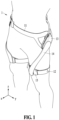
- FIG. 1 is a perspective view illustrating a user wearing a motion assist apparatus according to an embodiment.
- FIG. 2 is a perspective view illustrating a driving frame, a mount, a slider, and a slider housing according to an embodiment.
- FIG. 3 is an exploded perspective view illustrating the driving frame, an upper mount, a lower mount, a friction reducing member, a shaft, the slider, and the slider housing according to an embodiment.
- FIG. 4 is a cross-sectional view taken along a line IV-IV of FIG. 2 .
- a motion assist apparatus 1 may be worn by a user and assist the motion of the user.
- the user may be a human, an animal, or a robot, but examples are not limited thereto.
- the motion assist apparatus 1 may assist the motion of some joints of the upper or lower body of the user.
- the motion assist apparatus 1 may assist the motion of the lower body of the user by assisting at least one of the hip joint, the knee joint, and the ankle joint of the user.
- the motion assist apparatus 1 may assist the motion of the upper body of the user by assisting at least one of the shoulder joint, the elbow joint, and the wrist joint of the user.
- the motion assist apparatus 1 may assist the user in walking by assisting the motion of some lower body joints of the user.
- the motion assist apparatus 1 may include a proximal support 11, a distal support 12, an actuator 13, a driving frame 14, a slider housing 15, a slider 16, and a mount 17.
- the proximal support 11 and the distal support 12 may be opposite to each other based on one body part of the user and respectively support a proximal part and a distal part.
- the proximal support 11 may support the waist and/or the pelvis of the user and the distal support 12 may support the thigh, the knee, the calf, and/or the foot of the user.
- the proximal support 11 may include a detachable belt for supporting the waist of the user all around.
- the distal support 12 may include a detachable belt for supporting the thigh of the user all around.
- the proximal support 11 and the distal support 12 may be opposite to each other based on the upper arm of the user, and the proximal support 11 may support, for example, the shoulder and/or the back of the user and the distal support 12 may support, for example, the forearm of the user.
- the proximal support 11 may include a detachable belt for supporting the shoulder of the user all around and the distal support 12 may include a detachable belt for supporting the forearm of the user all around or a structure surrounding the forearm of the user all around.
- the proximal support 11 and the distal support 12 may move relative to each other on a sagittal plane.
- the distal support 12 may rotate relative to the proximal support 11 on the sagittal plane.
- the proximal support 11 and the distal support 12 may move relative to each other on a frontal plane.
- the distal support 12 may rotate relative to the proximal support 11 on the frontal plane.
- the driving frame 14 and the distal support 12 may move relative to each other on a transverse plane.
- the distal support 12 may rotate with the thigh of the user in close contact with the thigh of the user. That is, the distal support 12 may rotate relative to the driving frame 14. According to this structure, the wearability of the user may increase.
- the actuator 13 may be connected to the proximal support 11 and generate power.
- the actuator 13 may include, for example, a motor and a speed reducer.
- the motor may include at least one of a brush motor, a brushless motor, and a stepping motor.
- the motor may include at least one of an induction motor and a synchronous motor.
- the speed reducer may include, for example, a gear train.
- the driving frame 14 may transmit power generated by the actuator 13 to the distal support 12.
- the driving frame 14 may assist the motion of the hip joint of the user.
- the driving frame 14 may receive power from the actuator 13 and assist the flexion motion of the hip joint of the user.
- the driving frame 14 may receive power from the actuator 13 and assist the extension motion of the hip joint of the user.
- the description is provided that the driving frame 14 assists the motion of the hip joint of the user, but a function of the driving frame 14 is not limited thereto.
- the driving frame 14 may assist the motion of the shoulder or elbow joint of the user.
- the slider housing 15 may be connected to the distal support 12 and may face the driving frame 14.
- the slider housing 15 may have a shape surrounding the distal part of the user.
- the slider housing 15 may rotate relative to the driving frame 14 on the sagittal plane.
- the slider housing 15 may have a sliding space in which the slider 16 may move.
- the sliding space may be formed in the y-axis direction or the z-axis direction.
- the slider 16 may be slidably provided in the slider housing 15.
- the slider 16 may move along a rail provided in the slider housing 15.
- the slider 16 may be moved by elasticity of a spring provided in the slider housing 15.
- the slider 16 may move along the sliding space.
- the slider 16 may move in the y-axis direction or the z-axis direction with respect to the slider housing 15.
- the distal support 12 may move relative to the driving frame 14.
- the slider 16 may include a slider body 161, a slider head 162, and a head hole 163.
- the slider body 161 may be slidably provided in the sliding space.
- the slider head 162 may protrude from the slider body 161.
- the slider head 162 may be formed at the center of the slider body 161.
- the slider head 162 may be accommodated in the mount 17.
- the slider head 162 may have a convex shape in a direction away from the slider body 161.
- the head hole 163 may be formed through the slider head 162.
- the mount 17 may connect the driving frame 14 to the slider 16.
- the mount 17 may be disposed between the driving frame 14 and the slider 16.
- the slider 16 may not be directly connected to the driving frame 14. The magnitude of torsion, rotation, or shearing force transmitted from the driving frame 14 to the slider 16 may decrease.
- a shaft 18 and a friction reducing member 19 may be provided in the mount 17.
- the mount 17 may include a lower mount 171 and an upper mount 172.
- the lower mount 171 and the upper mount 172 may be provided on opposite sides based on the shaft 18 and may be coupled to each other.
- the shaft 18 may pass through the head hole 163 and be fixed to the slider head 162.
- the slider 16 may not rotate with respect to the shaft 18.
- the slider 16 may rotate integrally with the shaft 18.
- the slider housing 15 may rotate with respect to the mount 17.
- the distal support 12 may rotate with respect to the proximal support 11.
- the friction reducing member 19 which may be supported by the lower mount 171 and the upper mount 172.
- the friction reducing member 19 may be fixed inside the mount 17.
- the friction reducing member 19 may support the shaft 18.
- the friction reducing member 19 may be a bush into which the shaft 18 may be inserted.
- the friction reducing member 19 may be provided in plurality.
- the friction reducing members 19 may be provided as a pair.
- the slider head 162 may be provided between the pair of friction reducing members 19.
- the friction reducing member 19 is described as a bush herein, but the type of the friction reducing member 19 is not necessarily limited thereto.
- the friction reducing member 19 may be a bearing.
- FIG. 5 is a perspective view illustrating the lower mount according to an embodiment.
- FIG. 6 is a perspective view illustrating the upper mount according to an embodiment.
- FIG. 7 is a side view illustrating the friction reducing member supported by an upper holder and a lower groove according to an embodiment.
- FIG. 8 is a side view illustrating the shaft supported by a slider head according to an embodiment.
- the mount 17 may accommodate the slider head 162, the shaft 18, and the friction reducing member 19 therein.
- the lower mount 171 may include a lower body 1711, a main hole 1712, a lower groove 1713, a mount rib 1714, and a lower wing 1715.
- the lower body 1711 may accommodate the shaft 18.
- the main hole 1712 may be formed through the lower body 1711 and may accommodate the slider head 162.
- the main hole 1712 may be formed at the center of the lower body 1711.
- the lower groove 1713 may accommodate the friction reducing member 19.
- two lower grooves 1713 may be provided on both sides of the main hole 1712.
- the lower groove 1713 may be recessed into the lower body 1711.
- the lower groove 1713 may have a U shape.
- the width D of the lower groove 1713 may be greater than or equal to the outer diameter of the friction reducing member 19.
- the lower groove 1713 may communicate with the main hole 1712.
- the lower groove 1713 may also communicate with the outside of the lower body 1711.
- the shaft 18 may pass through the width D of the lower groove 1713 and be supported by the friction reducing member 19 and the slider head 162.
- the mount rib 1714 may be formed along the edge of the lower groove 1713.
- the mount rib 1714 may be formed at a part where the lower groove 1713 and the main hole 1712 communicate (hereinafter, referred to as a "first rib 1714a").
- the mount rib 1714 may also be formed at a part where the lower groove 1713 and the outside of the lower body 1711 communicate (hereinafter, referred to as a "second rib 1714b ").
- the first rib 1714a and the second rib 1714b may be formed in one lower groove 1713.
- the mount rib 1714 may support the friction reducing member 19. The separation of the friction reducing member 19 from the lower groove 1713 may decrease.
- the lower wing 1715 may protrude from the lower body 1711 toward a driving frame.
- the lower wing 1715 may be detachably connected to the driving frame.
- the lower wing 1715 may be rotated and connected to the driving frame after being accommodated in the driving frame.
- the lower wing 1715 may be screwed to the driving frame.
- the maintenance of a motion assist apparatus may be easy.
- the upper mount 172 may include an upper plate 1721, an upper holder 1722, a support 1723, and an upper wing 1724.
- the upper plate 1721 and the driving frame may face each other.
- the upper plate 1721 may be detachably coupled to the lower body 1711.
- the upper plate 1721 may be screwed to the lower body 1711.
- the shaft 18 or the friction reducing member 19 is damaged or worn out, the upper plate 1721 may be separated from the lower body 1711 to replace the damaged or worn component. The cost of maintenance of the motion assist apparatus may decrease.
- the upper holder 1722 may protrude from the upper plate 1721 toward a slider.
- the upper holders 1722 may be provided as a pair.
- the friction reducing member 19 may be supported by the upper holder 1722 and the lower body 1711 provided in opposite directions based on the shaft 18.
- the friction reducing member 19 may be fixed inside a mount. The friction reducing member 19 may not rotate with respect to the mount.
- a surface of the upper holder 1722 contacting the friction reducing member 19 may have a curved shape.
- the upper holder 1722 may cover a part of the friction reducing member 19.
- the shaking of the friction reducing member 19 may decrease.
- the stable rotation of the shaft 18 with respect to the friction reducing member 19 may be possible.
- the support 1723 may protrude from the upper plate 1721 toward the slider body 161.
- the support 1723 may be provided in contact with the slider head 162.
- the slider head 162 may not directly contact the upper plate 1721.
- the slider head 162 may be stably supported by the support 1723.
- a surface of the support 1723 contacting the slider head 162 may have a curved shape.
- the curvature of the support 1723 may be the same as that of the slider head 162.
- the upper wing 1724 may be accommodated in the lower groove 1713.
- the upper wing 1724 may protrude from the upper plate 1721 toward the slider.
- the upper wings 1724 may be provided as a pair facing each other in the longitudinal direction of the shaft 18.
- the upper wing 1724 may be spaced apart from the upper holder 1722.
- the upper wing 1724 may overlap with the upper holder 1722 based on the longitudinal direction of the shaft 18.
- the friction reducing member 19 may be provided between the slider head 162 and the upper wing 1724.
- the shaft 18 may not separate to the outside of the mount.
- the upper mount 172 When the upper mount 172 is coupled to the lower mount 171, the upper mount 172 may not move with respect to the lower mount 171.
- the upper mount 172 may be stably coupled to the lower mount 171.
- the upper wing 1724 may include a wing body 1724a and a wing head 1724b.
- the wing body 1724a may be inserted into the lower groove 1713.
- the mount rib 1714 may overlap with the wing body 1724a based on the longitudinal direction of the shaft 18.
- the friction reducing member 19 and the wing body 1724a may be accommodated between the first rib 1714a and the second rib 1714b.
- the friction reducing member 19 may be provided between the first rib 1714a and the wing body 1724a.
- the wing body 1724a may be provided between the friction reducing member 19 and the second rib 1714b.
- the range in which the friction reducing member 19 may move in the longitudinal direction of the shaft 18 may decrease.
- the noise and squeaks generated from the movement of the friction reducing member 19 may decrease.
- the wing head 1724b may protrude from the wing body 1724a in the outward direction and may be supported by the second rib 1714b.
- the outer edge of the lower body 1711 may have a smooth shape without protruding outwardly. The number of foreign materials penetrating into the mount may decrease. The damage or wear of the wing head 1724b due to the friction may decrease.
- the shaft 18 may include a curved surface 181 and a cutting surface 182.
- the curved surface 181 may contact an inner surface of the friction reducing member 19.
- the shaft 18 may rotate with respect to the friction reducing member 19.
- at least one cutting surface 182 may contact the slider head 162.
- the shaft 18 may not rotate with respect to the slider head 162.
- three cutting surfaces 182 are illustrated herein, but the number is not necessarily limited thereto.
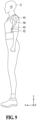
- FIG. 9 is a perspective view schematically illustrating a user wearing a motion assist apparatus on the upper arm of the user, according to an embodiment.
- a motion assist apparatus may be worn on the upper arm of a user U.
- an actuator 93 of the motion assist apparatus may be provided near the shoulder of the user U and a driving frame 94 may be connected to the actuator 93 and disposed along the upper arm of the user U.
- a slider housing 95 may be provided on the forearm of the user U.
- a distal support 92 may surround and support the forearm of the user U all around.
- a shaft may rotate with respect to a friction reducing member in a state supported by a slider head.
- a mount may include an upper mount and a lower mount provided on opposite sides based on the shaft and may be coupled to each other.
- the upper mount may include an upper plate and an upper holder protruding from the upper plate and configured to support the friction reducing member.
- the upper mount may further include a support protruding from the upper plate toward a slider body and provided in contact with the slider head.
- the slider head may have a convex shape in a direction away from the slider body.
- the lower mount may include a lower body configured to accommodate the shaft, a main hole formed through the lower body and configured to accommodate the slider head, and a lower groove configured to accommodate the friction reducing member and communicating with the main hole.
- the width of the lower groove may be greater than or equal to the outer diameter of the friction reducing member.
- the upper mount may further include an upper wing protruding from the upper plate toward a slider.
- the upper wing may be spaced apart from the upper holder.
- the friction reducing member may be provided between the slider head and the upper wing.
- the lower mount may further include a mount rib formed along the edge of the lower groove.
- the mount rib may cover at least a part of the upper wing.
- the mount rib may overlap with the upper wing based on the longitudinal direction of the shaft.
- the upper wing may include a wing body inserted into the lower groove and a wing head protruding from the wing body in the outward direction and supported by the mount rib.
- the shaft may include a cutting surface contacting the slider head.
- the friction reducing member may be a bush.
- the friction reducing member may be a bearing.
Landscapes
- Health & Medical Sciences (AREA)
- General Health & Medical Sciences (AREA)
- Physical Education & Sports Medicine (AREA)
- Life Sciences & Earth Sciences (AREA)
- Animal Behavior & Ethology (AREA)
- Rehabilitation Therapy (AREA)
- Pain & Pain Management (AREA)
- Epidemiology (AREA)
- Public Health (AREA)
- Veterinary Medicine (AREA)
- Orthopedic Medicine & Surgery (AREA)
- Biophysics (AREA)
- Rehabilitation Tools (AREA)
- Manipulator (AREA)
Applications Claiming Priority (3)
| Application Number | Priority Date | Filing Date | Title |
|---|---|---|---|
| KR20220058540 | 2022-05-12 | ||
| KR1020220112086A KR102643944B1 (ko) | 2022-05-12 | 2022-09-05 | 마찰 저감 부재가 수용된 마운트를 포함하는 운동 보조 장치 |
| PCT/KR2023/006183 WO2023219345A2 (fr) | 2022-05-12 | 2023-05-08 | Appareil d'aide au mouvement comprenant un support recevant un élément de réduction de frottement |
Publications (4)
| Publication Number | Publication Date |
|---|---|
| EP4417178A2 true EP4417178A2 (fr) | 2024-08-21 |
| EP4417178A4 EP4417178A4 (fr) | 2025-05-14 |
| EP4417178C0 EP4417178C0 (fr) | 2026-03-11 |
| EP4417178B1 EP4417178B1 (fr) | 2026-03-11 |
Family
ID=88730654
Family Applications (1)
| Application Number | Title | Priority Date | Filing Date |
|---|---|---|---|
| EP23803768.3A Active EP4417178B1 (fr) | 2022-05-12 | 2023-05-08 | Appareil d'aide au mouvement comprenant un support recevant un élément de réduction de frottement |
Country Status (4)
| Country | Link |
|---|---|
| US (1) | US20240307247A1 (fr) |
| EP (1) | EP4417178B1 (fr) |
| KR (1) | KR20240031994A (fr) |
| WO (1) | WO2023219345A2 (fr) |
Family Cites Families (8)
| Publication number | Priority date | Publication date | Assignee | Title |
|---|---|---|---|---|
| AU688348B2 (en) * | 1993-07-09 | 1998-03-12 | Kinetecs, Inc. | Exercise apparatus and technique |
| EP2036518B1 (fr) * | 2006-06-29 | 2013-02-27 | Honda Motor Co., Ltd. | Dispositif d'aide à la marche |
| JP5161036B2 (ja) * | 2008-11-06 | 2013-03-13 | 本田技研工業株式会社 | 歩行補助装置 |
| US9022958B2 (en) * | 2011-06-10 | 2015-05-05 | Honda Motor Co., Ltd. | Walking assistance device |
| KR102352338B1 (ko) * | 2014-07-17 | 2022-01-18 | 삼성전자주식회사 | 연결 모듈 및 이를 포함하는 운동 보조 장치 |
| KR102479563B1 (ko) * | 2017-07-24 | 2022-12-20 | 삼성전자주식회사 | 운동 보조 장치 |
| KR102449705B1 (ko) * | 2017-08-23 | 2022-09-30 | 삼성전자주식회사 | 운동 보조 장치 |
| JP7112969B2 (ja) * | 2019-01-11 | 2022-08-04 | トヨフレックス株式会社 | 動作補助装置 |
-
2023
- 2023-05-08 EP EP23803768.3A patent/EP4417178B1/fr active Active
- 2023-05-08 WO PCT/KR2023/006183 patent/WO2023219345A2/fr not_active Ceased
-
2024
- 2024-02-26 KR KR1020240027531A patent/KR20240031994A/ko active Pending
- 2024-05-23 US US18/672,556 patent/US20240307247A1/en active Pending
Also Published As
| Publication number | Publication date |
|---|---|
| WO2023219345A3 (fr) | 2024-02-01 |
| EP4417178C0 (fr) | 2026-03-11 |
| WO2023219345A2 (fr) | 2023-11-16 |
| EP4417178B1 (fr) | 2026-03-11 |
| EP4417178A4 (fr) | 2025-05-14 |
| US20240307247A1 (en) | 2024-09-19 |
| KR20240031994A (ko) | 2024-03-08 |
Similar Documents
| Publication | Publication Date | Title |
|---|---|---|
| JP7549845B2 (ja) | 運動補助装置 | |
| KR102662375B1 (ko) | 운동 보조 장치 | |
| KR102250260B1 (ko) | 연결 모듈 및 이를 포함하는 운동 보조 장치 | |
| US12419801B2 (en) | Self-aligning mechanisms in passive and powered exoskeletons | |
| KR102663308B1 (ko) | 체결 알림 기능을 갖는 링크를 포함하는 운동 보조 장치 | |
| EP4417178A2 (fr) | Appareil d'aide au mouvement comprenant un support recevant un élément de réduction de frottement | |
| KR102643944B1 (ko) | 마찰 저감 부재가 수용된 마운트를 포함하는 운동 보조 장치 | |
| US11452659B2 (en) | Legged mobility exoskeleton device with enhanced actuator mechanism employing magnetic/electrical coupling | |
| KR102352338B1 (ko) | 연결 모듈 및 이를 포함하는 운동 보조 장치 | |
| US20240238149A1 (en) | Motion assistance apparatus including link having fastening notification function | |
| CN118475329A (zh) | 包括容纳减摩构件的安装件的运动辅助设备 | |
| KR20220166187A (ko) | 볼이 수용된 슬라이더를 포함하는 운동 보조 장치 | |
| US20240009058A1 (en) | Exercise assistance device including slider in which balls are accomodated | |
| US12138215B2 (en) | Reconfigurable motion assistance apparatus | |
| US20240058198A1 (en) | Motion assistance device comprising ball mount coupling structure | |
| JP6713684B2 (ja) | 動作アシスト装置 | |
| US11331241B2 (en) | Legged mobility exoskeleton device with enhanced actuator mechanism employing magnetic coupling | |
| US20240252380A1 (en) | Exercise assistance apparatus including magnet | |
| US20250196322A1 (en) | Assembly-type structure for fixing motor and exercise assistance device including same | |
| EP4151192B1 (fr) | Support ayant un ressort bistable, et appareil d'aide à l'exercice le comprenant | |
| Janowski et al. | Method of Studying a Process of Turning in an Orthotic Robot | |
| KR20220163262A (ko) | 볼 마운트 결합 구조를 포함하는 운동 보조 장치 |
Legal Events
| Date | Code | Title | Description |
|---|---|---|---|
| STAA | Information on the status of an ep patent application or granted ep patent |
Free format text: STATUS: THE INTERNATIONAL PUBLICATION HAS BEEN MADE |
|
| PUAI | Public reference made under article 153(3) epc to a published international application that has entered the european phase |
Free format text: ORIGINAL CODE: 0009012 |
|
| STAA | Information on the status of an ep patent application or granted ep patent |
Free format text: STATUS: REQUEST FOR EXAMINATION WAS MADE |
|
| 17P | Request for examination filed |
Effective date: 20240515 |
|
| AK | Designated contracting states |
Kind code of ref document: A2 Designated state(s): AL AT BE BG CH CY CZ DE DK EE ES FI FR GB GR HR HU IE IS IT LI LT LU LV MC ME MK MT NL NO PL PT RO RS SE SI SK SM TR |
|
| A4 | Supplementary search report drawn up and despatched |
Effective date: 20250410 |
|
| RIC1 | Information provided on ipc code assigned before grant |
Ipc: A61H 3/00 20060101ALI20250404BHEP Ipc: A61H 1/02 20060101AFI20250404BHEP |
|
| DAV | Request for validation of the european patent (deleted) | ||
| DAX | Request for extension of the european patent (deleted) | ||
| GRAP | Despatch of communication of intention to grant a patent |
Free format text: ORIGINAL CODE: EPIDOSNIGR1 |
|
| STAA | Information on the status of an ep patent application or granted ep patent |
Free format text: STATUS: GRANT OF PATENT IS INTENDED |
|
| INTG | Intention to grant announced |
Effective date: 20251217 |
|
| GRAS | Grant fee paid |
Free format text: ORIGINAL CODE: EPIDOSNIGR3 |
|
| GRAA | (expected) grant |
Free format text: ORIGINAL CODE: 0009210 |
|
| STAA | Information on the status of an ep patent application or granted ep patent |
Free format text: STATUS: THE PATENT HAS BEEN GRANTED |
|
| AK | Designated contracting states |
Kind code of ref document: B1 Designated state(s): AL AT BE BG CH CY CZ DE DK EE ES FI FR GB GR HR HU IE IS IT LI LT LU LV MC ME MK MT NL NO PL PT RO RS SE SI SK SM TR |
|
| REG | Reference to a national code |
Ref country code: CH Ref legal event code: F10 Free format text: ST27 STATUS EVENT CODE: U-0-0-F10-F00 (AS PROVIDED BY THE NATIONAL OFFICE) Effective date: 20260311 Ref country code: GB Ref legal event code: FG4D |
|
| REG | Reference to a national code |
Ref country code: DE Ref legal event code: R096 Ref document number: 602023013516 Country of ref document: DE |
|
| REG | Reference to a national code |
Ref country code: IE Ref legal event code: FG4D |
|
| U01 | Request for unitary effect filed |
Effective date: 20260326 |