EP4417290A1 - Dispositif de filtration pour un appareil ménager à circulation d'eau - Google Patents
Dispositif de filtration pour un appareil ménager à circulation d'eau Download PDFInfo
- Publication number
- EP4417290A1 EP4417290A1 EP24154762.9A EP24154762A EP4417290A1 EP 4417290 A1 EP4417290 A1 EP 4417290A1 EP 24154762 A EP24154762 A EP 24154762A EP 4417290 A1 EP4417290 A1 EP 4417290A1
- Authority
- EP
- European Patent Office
- Prior art keywords
- filtration device
- water
- household appliance
- filter
- housing
- Prior art date
- Legal status (The legal status is an assumption and is not a legal conclusion. Google has not performed a legal analysis and makes no representation as to the accuracy of the status listed.)
- Pending
Links
Images



Classifications
-
- C—CHEMISTRY; METALLURGY
- C02—TREATMENT OF WATER, WASTE WATER, SEWAGE, OR SLUDGE
- C02F—TREATMENT OF WATER, WASTE WATER, SEWAGE, OR SLUDGE
- C02F1/00—Treatment of water, waste water, or sewage
- C02F1/001—Processes for the treatment of water whereby the filtration technique is of importance
-
- B—PERFORMING OPERATIONS; TRANSPORTING
- B01—PHYSICAL OR CHEMICAL PROCESSES OR APPARATUS IN GENERAL
- B01D—SEPARATION
- B01D35/00—Filtering devices having features not specifically covered by groups B01D24/00 - B01D33/00, or for applications not specifically covered by groups B01D24/00 - B01D33/00; Auxiliary devices for filtration; Filter housing constructions
- B01D35/02—Filters adapted for location in special places, e.g. pipe-lines, pumps, stop-cocks
-
- B—PERFORMING OPERATIONS; TRANSPORTING
- B01—PHYSICAL OR CHEMICAL PROCESSES OR APPARATUS IN GENERAL
- B01D—SEPARATION
- B01D29/00—Filters with filtering elements stationary during filtration, e.g. pressure or suction filters, not covered by groups B01D24/00 - B01D27/00; Filtering elements therefor
- B01D29/11—Filters with filtering elements stationary during filtration, e.g. pressure or suction filters, not covered by groups B01D24/00 - B01D27/00; Filtering elements therefor with bag, cage, hose, tube, sleeve or like filtering elements
- B01D29/13—Supported filter elements
- B01D29/23—Supported filter elements arranged for outward flow filtration
-
- B—PERFORMING OPERATIONS; TRANSPORTING
- B01—PHYSICAL OR CHEMICAL PROCESSES OR APPARATUS IN GENERAL
- B01D—SEPARATION
- B01D29/00—Filters with filtering elements stationary during filtration, e.g. pressure or suction filters, not covered by groups B01D24/00 - B01D27/00; Filtering elements therefor
- B01D29/11—Filters with filtering elements stationary during filtration, e.g. pressure or suction filters, not covered by groups B01D24/00 - B01D27/00; Filtering elements therefor with bag, cage, hose, tube, sleeve or like filtering elements
- B01D29/31—Self-supporting filtering elements
- B01D29/35—Self-supporting filtering elements arranged for outward flow filtration
-
- B—PERFORMING OPERATIONS; TRANSPORTING
- B01—PHYSICAL OR CHEMICAL PROCESSES OR APPARATUS IN GENERAL
- B01D—SEPARATION
- B01D29/00—Filters with filtering elements stationary during filtration, e.g. pressure or suction filters, not covered by groups B01D24/00 - B01D27/00; Filtering elements therefor
- B01D29/60—Filters with filtering elements stationary during filtration, e.g. pressure or suction filters, not covered by groups B01D24/00 - B01D27/00; Filtering elements therefor integrally combined with devices for controlling the filtration
- B01D29/603—Filters with filtering elements stationary during filtration, e.g. pressure or suction filters, not covered by groups B01D24/00 - B01D27/00; Filtering elements therefor integrally combined with devices for controlling the filtration by flow measuring
-
- B—PERFORMING OPERATIONS; TRANSPORTING
- B01—PHYSICAL OR CHEMICAL PROCESSES OR APPARATUS IN GENERAL
- B01D—SEPARATION
- B01D29/00—Filters with filtering elements stationary during filtration, e.g. pressure or suction filters, not covered by groups B01D24/00 - B01D27/00; Filtering elements therefor
- B01D29/60—Filters with filtering elements stationary during filtration, e.g. pressure or suction filters, not covered by groups B01D24/00 - B01D27/00; Filtering elements therefor integrally combined with devices for controlling the filtration
- B01D29/606—Filters with filtering elements stationary during filtration, e.g. pressure or suction filters, not covered by groups B01D24/00 - B01D27/00; Filtering elements therefor integrally combined with devices for controlling the filtration by pressure measuring
-
- B—PERFORMING OPERATIONS; TRANSPORTING
- B01—PHYSICAL OR CHEMICAL PROCESSES OR APPARATUS IN GENERAL
- B01D—SEPARATION
- B01D29/00—Filters with filtering elements stationary during filtration, e.g. pressure or suction filters, not covered by groups B01D24/00 - B01D27/00; Filtering elements therefor
- B01D29/62—Regenerating the filter material in the filter
- B01D29/64—Regenerating the filter material in the filter by scrapers, brushes, nozzles, or the like, acting on the cake side of the filtering element
- B01D29/6469—Regenerating the filter material in the filter by scrapers, brushes, nozzles, or the like, acting on the cake side of the filtering element scrapers
- B01D29/6476—Regenerating the filter material in the filter by scrapers, brushes, nozzles, or the like, acting on the cake side of the filtering element scrapers with a rotary movement with respect to the filtering element
-
- B—PERFORMING OPERATIONS; TRANSPORTING
- B01—PHYSICAL OR CHEMICAL PROCESSES OR APPARATUS IN GENERAL
- B01D—SEPARATION
- B01D29/00—Filters with filtering elements stationary during filtration, e.g. pressure or suction filters, not covered by groups B01D24/00 - B01D27/00; Filtering elements therefor
- B01D29/88—Filters with filtering elements stationary during filtration, e.g. pressure or suction filters, not covered by groups B01D24/00 - B01D27/00; Filtering elements therefor having feed or discharge devices
- B01D29/94—Filters with filtering elements stationary during filtration, e.g. pressure or suction filters, not covered by groups B01D24/00 - B01D27/00; Filtering elements therefor having feed or discharge devices for discharging the filter cake, e.g. chutes
-
- B—PERFORMING OPERATIONS; TRANSPORTING
- B01—PHYSICAL OR CHEMICAL PROCESSES OR APPARATUS IN GENERAL
- B01D—SEPARATION
- B01D35/00—Filtering devices having features not specifically covered by groups B01D24/00 - B01D33/00, or for applications not specifically covered by groups B01D24/00 - B01D33/00; Auxiliary devices for filtration; Filter housing constructions
- B01D35/14—Safety devices specially adapted for filtration; Devices for indicating clogging
- B01D35/143—Filter condition indicators
- B01D35/1435—Filter condition indicators with alarm means
-
- B—PERFORMING OPERATIONS; TRANSPORTING
- B01—PHYSICAL OR CHEMICAL PROCESSES OR APPARATUS IN GENERAL
- B01D—SEPARATION
- B01D35/00—Filtering devices having features not specifically covered by groups B01D24/00 - B01D33/00, or for applications not specifically covered by groups B01D24/00 - B01D33/00; Auxiliary devices for filtration; Filter housing constructions
- B01D35/26—Filters with built-in pumps filters provided with a pump mounted in or on the casing
-
- B—PERFORMING OPERATIONS; TRANSPORTING
- B01—PHYSICAL OR CHEMICAL PROCESSES OR APPARATUS IN GENERAL
- B01D—SEPARATION
- B01D35/00—Filtering devices having features not specifically covered by groups B01D24/00 - B01D33/00, or for applications not specifically covered by groups B01D24/00 - B01D33/00; Auxiliary devices for filtration; Filter housing constructions
- B01D35/30—Filter housing constructions
-
- D—TEXTILES; PAPER
- D06—TREATMENT OF TEXTILES OR THE LIKE; LAUNDERING; FLEXIBLE MATERIALS NOT OTHERWISE PROVIDED FOR
- D06F—LAUNDERING, DRYING, IRONING, PRESSING OR FOLDING TEXTILE ARTICLES
- D06F39/00—Details of washing machines not specific to a single type of machines covered by groups D06F9/00 - D06F27/00
- D06F39/10—Filtering arrangements
-
- A—HUMAN NECESSITIES
- A47—FURNITURE; DOMESTIC ARTICLES OR APPLIANCES; COFFEE MILLS; SPICE MILLS; SUCTION CLEANERS IN GENERAL
- A47L—DOMESTIC WASHING OR CLEANING; SUCTION CLEANERS IN GENERAL
- A47L15/00—Washing or rinsing machines for crockery or tableware
- A47L15/42—Details
- A47L15/4202—Water filter means or strainers
- A47L15/4206—Tubular filters
-
- A—HUMAN NECESSITIES
- A47—FURNITURE; DOMESTIC ARTICLES OR APPLIANCES; COFFEE MILLS; SPICE MILLS; SUCTION CLEANERS IN GENERAL
- A47L—DOMESTIC WASHING OR CLEANING; SUCTION CLEANERS IN GENERAL
- A47L15/00—Washing or rinsing machines for crockery or tableware
- A47L15/42—Details
- A47L15/4202—Water filter means or strainers
- A47L15/4208—Arrangements to prevent clogging of the filters, e.g. self-cleaning
-
- C—CHEMISTRY; METALLURGY
- C02—TREATMENT OF WATER, WASTE WATER, SEWAGE, OR SLUDGE
- C02F—TREATMENT OF WATER, WASTE WATER, SEWAGE, OR SLUDGE
- C02F2101/00—Nature of the contaminant
- C02F2101/30—Organic compounds
- C02F2101/32—Hydrocarbons, e.g. oil
-
- C—CHEMISTRY; METALLURGY
- C02—TREATMENT OF WATER, WASTE WATER, SEWAGE, OR SLUDGE
- C02F—TREATMENT OF WATER, WASTE WATER, SEWAGE, OR SLUDGE
- C02F2103/00—Nature of the water, waste water, sewage or sludge to be treated
- C02F2103/002—Grey water, e.g. from clothes washers, showers or dishwashers
-
- C—CHEMISTRY; METALLURGY
- C02—TREATMENT OF WATER, WASTE WATER, SEWAGE, OR SLUDGE
- C02F—TREATMENT OF WATER, WASTE WATER, SEWAGE, OR SLUDGE
- C02F2201/00—Apparatus for treatment of water, waste water or sewage
- C02F2201/002—Construction details of the apparatus
-
- C—CHEMISTRY; METALLURGY
- C02—TREATMENT OF WATER, WASTE WATER, SEWAGE, OR SLUDGE
- C02F—TREATMENT OF WATER, WASTE WATER, SEWAGE, OR SLUDGE
- C02F2307/00—Location of water treatment or water treatment device
- C02F2307/12—Location of water treatment or water treatment device as part of household appliances such as dishwashers, laundry washing machines or vacuum cleaners
Definitions
- the invention relates to a filtration device, in particular for filtering microplastics, for a water-conducting household appliance, wherein the filtration device comprises a housing. Furthermore, the invention relates to a water-conducting household appliance with a filtration device, in particular for filtering microplastics.
- Microplastics are solid, insoluble, particulate and non-biodegradable synthetic materials or plastics.
- the microplastic particles are in the micrometer or nanometer range in size.
- Microplastics are components of detergents, soaps, etc.
- synthetic textiles or clothing are washed, synthetic textile components are dissolved into the smallest synthetic fibers.
- the unfiltered microplastic particles and fibers have a significant harmful effect on aquatic flora and fauna and thus also on humans as part of the food chain. Therefore, water-carrying household appliances are equipped with filter devices. However, these are often not able to effectively remove the microplastic particles and fibers. More effective filters, on the other hand, have the disadvantage that they clog up quickly and thus require considerable maintenance.
- the object of the invention is to provide an improved filtration, in particular for the filtration of microplastics, for water-conducting household appliances.
- a filtration device in particular for filtering microplastics for a water-conducting household appliance, wherein the filtration device comprises a housing in which a filter element is arranged, wherein the filter element is designed such that it encloses an inner cavity which is fluidically connected to a supply element, wherein a first drainage element is arranged along the height axis Z above the filter element, wherein a second drainage element is arranged along the height axis Z below the filter element.
- a corresponding water-conducting household appliance is in particular a washing machine.
- An embodiment according to the invention achieves effective filtering of microplastic particles and fibers.
- the first drainage element is suitable and intended to drain the filtered water only during a pumping process of the household appliance.
- the second drainage element is suitable and intended to drain the filtered water only after the end of a pumping process of the household appliance.
- the water enters the filtration device and thus into the inner cavity. While the water passes through the filter element, the microplastic particles and fibers remain in the inner cavity. The water exits the filter element upwards along the height axis Z and thus reaches the first drainage element, through which it then exits the filtration device. After the pumping process has ended, no water or only a small amount of return water enters the filtration device.
- the remaining water exits the filter element downwards along the height axis Z and is then guided out of the filtration device through the second drainage element.
- the filtered microplastic particles and fibers collect within the filter element on a lower inner surface.
- the filter element is essentially hollow-cylindrical.
- the filter element has an essentially circular cross-section.
- other differently formed cross-sections are also conceivable, for example elliptical, square, rectangular, triangular or another polygonal shape.
- the filter element has a support structure on which at least one filter screen is arranged.
- the filter screen advantageously forms a closed cylinder shell.
- the support structure is advantageously designed as a rib structure. It is advantageous that the rib elements belonging to the rib structure are arranged on an outer surface of the filter screen.
- an inner element extending along a longitudinal axis X is arranged rotatably within the inner cavity.
- the inner element contacts an inner surface of the at least one filter screen at least in sections.
- filtered microplastic particles and fibers are collected by means of a rotation of the inner element.
- the preferred circular cross-section of the filter element promotes a rotation of the inner element along an inner surface of the filter screen.
- the inner element comprises two angle elements extending along the longitudinal axis X. Furthermore, a gap is preferably provided between the two angle elements.
- the inner element divides an inner cavity into an upper region and a lower region. During the pumping process, a large part of the microplastic particles and fibers are advantageously located in an upper region of the inner cavity. When the pumping process is completed, the microplastic particles and fibers reach the lower region of the inner cavity.
- the design of the angle elements advantageously represents a type of guide for the microplastic particles and fibers to the gap. Due to the design of the inner element, only a small part of the lower region of the inner cavity will leave it again during a further pumping process.
- the inner element advantageously comprises a lip element which contacts an inner surface of the filter screen. It is also advantageous that a first outer element of the filter element is arranged rotatably on the housing of the filtration device.
- the first outer element is preferably connected to the inner element in such a way that it can be rotated by means of the first outer element.
- An advantageous rigid connection between the first outer element and the inner element would be conceivable here.
- the connection can be a force-fitting and/or form-fitting connection or also a material-fitting connection. A rotational movement of the first outer element can thus be transmitted to the inner element. Due to the advantageous rotational movement in conjunction with the contact of the lip element on the inner surface of the filter screen, Microplastic particles and fibers adhering to the filter sieve are removed and finally collected in a lower area of the inner cavity.
- the filter element can be removed from the housing.
- the filter element can thus advantageously be removed from the housing for cleaning purposes.
- the microplastic particles and fibers advantageously collected in the lower region of the inner cavity can thus be removed from the filter element in a simple manner.
- the housing of the filtration device comprises at least one receiving element which is intended to receive and store the filter element.
- a locking mechanism is provided which fixes the filter element in the housing of the filtration device. The locking mechanism is advantageously provided between the outer element of the filter element and the housing of the filtration device.
- the inner element is helical.
- an outer contact surface of the helical inner element contacts an inner surface of the filter screen.
- a second outer element is arranged on the housing.
- the second outer element is cup-shaped.
- rotation of the helical inner element conveys the filtered microplastic particles and fibers into the outer element.
- the microplastic particles and fibers are deposited on the inner surface of the filter screen.
- the second outer element is removable from the filter element and the housing of the filtration device. This provides an extremely simple way of cleaning and emptying the filter element.
- a drive device is provided by means of which the rotation of the helical inner element is driven.
- the drive device is operatively connected to the helical inner element by means of a transmission device.
- the drive device can be, for example, an electric motor.
- the transmission device can be, for example, a gear, a shaft, a belt or a similarly suitable transmission device.
- the housing of the filtration device and the support structure of the filter element are advantageously made of plastic.
- a design made of metal or a metal alloy would also be conceivable.
- the filter screen of the filter element is preferably made of microporous and hydrophobic plastic.
- the filter screen can be in the form of a solid body or a mat.
- a design of the filter screen as a nonwoven fabric would also be conceivable.
- the present object of the invention is also achieved by a water-conducting household appliance, comprising at least one suds container and at least one filtration device, according to one of the previously described embodiments.
- the household appliance can be equipped with all of the features already described above in the context of the filtration device, individually or in combination with one another, and vice versa.
- Such a household appliance advantageously comprises a housing in which the at least one suds container is arranged.
- the filtration device is preferably arranged in the housing of the household appliance.
- the filtration device is preferably provided in an upper area of the household appliance so that it is easily accessible for emptying.
- the household appliance is preferably a washing machine. However, a dishwasher would also be conceivable.
- the objects to be washed are placed in the suds container. During the washing process, a washing liquid in the form of water mixed with a treatment agent is then introduced into the suds container.
- the water-conducting household appliance preferably comprises a pumping device which conveys water from the tub to the at least one filtration device. After or during the washing process, the waste water is thus pumped out of the tub by means of the pumping device.
- the first drain element is advantageously fluidically connected to the drain of the water-conducting household appliance. It would also be conceivable for the first drain element to be connected to the tub of the household appliance. The filtered water is drained from the first drain element by means of the pumping device.
- the second drain element is preferably connected to a drain of the water-conducting household appliance via a bypass line. An additional pumping device is advantageously provided in the second drain element and/or in the bypass line, by means of which the water can be conveyed from the second drain element or the filter element or the filtration device.
- the water-conducting household appliance comprises a control device which controls the filtration device.
- the control device also controls other functions of the household appliance.
- the control device controls the drive device of the filtration device.
- the drive device can be activated after the pumping process has ended, so that the filtered microplastic particles and fibers are conveyed into the second outer element. Before the next pumping process, the filtered microplastic particles and fibers are thus removed from the filter sieve.
- the additional pumping device is not activated during the pumping process of the pumping device, so that no water can be drained off via the second drainage element.
- the filtered water is therefore advantageously drained off only via the first drainage element during the pumping process.
- the additional pumping device is activated.
- the filtered water can advantageously be drained off only via the second drainage element, since it no longer flows off via the first drainage element.
- At least one first sensor device is provided, by means of which a need to empty the filter element can be detected.
- at least one first sensor device is connected to the control device in terms of signaling.
- the control device transmits a signal to an indication device.
- the indication device can be an optical indication device, for example a light or an acoustic indication device.
- the first sensor device comprises at least one sensor which detects a reduced flow through the filter element.
- a sensor could preferably be provided by means of which a water level detection is enabled, preferably in the second filter element.
- a sensor can be provided which detects a differential pressure between the supply element and the first and/or the second discharge element.
- a sensor can be provided which detects the flow from the second discharge element.
- the emptying requirement exists when the flow falls below a threshold value.
- a preferred sensor could be an optical Sensor that can detect the presence of a certain amount of microplastic particles or fibers in the filter element.
- a second sensor device which detects the opening state of the filter element.
- the control device preferably prevents a washing program from starting as long as the filter element is not closed. This ensures that a washing process can only take place with appropriate filtering.
- a filtration device 1 is shown, in particular for filtering microplastics for a water-conducting household appliance 100.
- the filtration device 1 comprises a housing 2 in which a filter element 3 is arranged, wherein the filter element 3 is designed such that it encloses an inner cavity 4 which is fluidically connected to a supply element 5, wherein a first drainage element 6 is arranged along the height axis Z above the filter element 3, wherein a second drainage element 7 is arranged along the height axis Z below the filter element 3.
- the filtration device 1 extends along a height axis Z, a longitudinal axis X and a width axis Y.
- a household appliance 100 is shown. This extends along a height axis Z ⁇ , a longitudinal axis X' and a width axis Y ⁇ .
- the filtration device 1 comprises a housing 2. This is essentially circular-cylindrical in shape. However, the design of the shape of the housing 2 should not represent a restriction of generality. Since the filtration device 1 is arranged within the household appliance 100, the shape of the housing 2 of the filtration device 1 can be adapted to the respective conditions of the household appliance 100.
- the housing 2 of the filtration device 1 extends along a vertical axis Z. Furthermore, a supply line element 5 is provided, which is arranged along the vertical axis Z between the first drainage element 6 and the second drainage element 7.
- the supply line element 5 can be integrated in the housing 2 or arranged thereon. Furthermore, it is suitable and intended for a supply line 5, for example in the form of a hose or pipe, to be arranged thereon. Both the first drainage element 6 and the second drainage element 7 can be integrated in the housing 2 or arranged thereon. Furthermore, they are suitable and intended for a drainage line, for example in the form of a hose or pipe, to be arranged thereon.
- Figure 3b It can be seen that the first drainage element 6 and the second drainage element 7 are diametrically opposite.
- the first drainage element 6 is suitable and intended to drain the filtered water only during a pumping process of the household appliance 100.
- the second drainage element 7 is suitable and intended to drain the filtered water only after the end of a pumping process of the household appliance 100.
- an additional pump device 108 is provided, by means of which the water can be conveyed from the second drainage element 7 or the filter element 3 or the filtration device 1.
- the first filter element 3 is essentially hollow-cylindrical. According to the embodiment shown here, the first filter element 3 has an essentially circular cross-section. However, other cross-sections are also conceivable, for example elliptical or polygonal.
- the first filter element 3 has a support structure 8, on which at least one filter screen 9 is arranged.
- the hollow-cylindrical design also defines the inner cavity 4.
- the support structure 8 comprises at least two first rib elements 8a extending along the longitudinal axis X and at least two second rib elements 8b extending along a circumferential direction U.
- the first rib elements 8a extend between two ring-like support elements 8c arranged along the longitudinal axis X.
- the first rib elements 8a and the second rib elements 8b are arranged on an outer surface 9b of the filter screen 9.
- the filter screen 9 is thus arranged radially further inward than the first rib elements 8a and the second rib elements 8b.
- the inner surface 9a of the filter screen 9 defines the inner cavity 4.
- the water to be filtered passes into this inner cavity 4 from the supply element 5.
- the water passes through the filter screen 9.
- the water then exits from the first drainage element 6.
- the filtration device 1 After the pumping process, the water then exits the filtration device 1 from the second drainage element 7.
- an inner element 10 extending along a longitudinal axis X is arranged rotatably, which at least partially contacts the inner surface 9a of the at least one filter screen 9. By rotating the inner element 10, filtered microplastic particles and fibers 20 are collected.
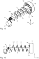
- Two embodiments of the inner element 10 are shown here. The first embodiment is shown in the Figures 1 to 11b The second embodiment is shown in the Figures 12 to 18 shown.
- the inner element 10 comprises two angle elements 11 extending along the longitudinal axis X.
- the inner element 10 comprises an end piece 23 at each of its ends as seen along the longitudinal axis X.
- the two angle elements 11 each open into the end pieces 23.
- the end pieces 23 are essentially circular segment-shaped and each comprise a rotation pin 24.
- the rotation pins 24 are each arranged rotatably in a receptacle 25a, 25b of the support structure 8.
- the receptacles 25a, 25b are each connected to the ring-like support elements 8c.
- the rear receptacle 25b lies in the opening of the ring-like support element 8c.
- At least one third rib element 8d is provided, which connects the ring-like support element 8c to the rear ring-like receptacle 25b.
- two third rib elements 8d are provided, arranged in a cross-like manner within the opening of the ring-like support element 8c.
- the supply element 5 is arranged along the vertical axis Z above the rear ring-like receptacle 25b. The water to be filtered can thus reach the inner cavity 4 unhindered.
- a disk-like front element 27 is arranged on the ring-like support element 8c at the front along the longitudinal axis X.
- the front element 27 seals off the inner cavity 4.
- the front element 27 rests on the ring-like support element 8c from the front.
- the front receptacle 25a is provided as an opening or bore in the front element 27.
- a first outer element 14 of the filter element 3 is arranged rotatably on the housing 2 of the filtration device 1.
- This first outer element 14 is connected to the inner element 10 in such a way that the latter can be rotated by means of the first outer element 14.
- a rotation of the first outer element 14 can be carried out, for example, by a manual movement.
- the outer element 14 comprises a cup-like receptacle 14a. This cup-like receptacle 14a projects into the front receptacle 25a or into the opening or into the bore of the front element 27 and at the same time accommodates the front rotation pin 24.
- the cup-like receptacle 14a is rotatable relative to the front receptacle 25a. Furthermore, a connecting element 26 is provided, by means of which the outer element 14 is rigidly connected to the inner element 10, in particular to the rotary pin 24.
- the connecting element 26 can be a pin, a rivet, a screw or the like. Of course, other connections between the outer element 14 and the inner element 10 are also conceivable.
- the angle elements 11 extend along the longitudinal axis X over essentially the entire length of the inner cavity 4.
- the angle elements 11 also extend along the width axis Y over essentially the entire width of the inner cavity 4.
- the angle elements 11 preferably end close to the inner surface 9a of the filter screen 9, but do not touch it.
- An angle element 11 comprises two legs which enclose an angle ⁇ .
- the angle ⁇ is in a range between 45° and 135°, preferably around 90°.
- a gap 12 is provided between the two angle elements 11.
- the gap 12 extends along the longitudinal axis X between the two end pieces 23 and spaces the two angle elements 11 or the opposite legs of the two angle elements 11 along the width axis Y.
- the inner element 10 separates the inner cavity 4 into an upper area 4a and a lower area 4b.
- a large part of the microplastic particles and fibers 20 are in the upper area 4a of the inner cavity 4.
- the water flows radially outwards through the filter screen 9. This is shown in the Figures 10 and 11a During the pumping process, the water only exits the filtration device 1 via the first drainage element 6.
- the microplastic particles and fibers 20 pass through the gap 12 into the lower area 4b of the inner cavity 4. This is done by the effect of the gravitational force, shown in Fig. 11a, 11b with arrow 28.
- the design of the angle elements 11 represents a type of guide for the microplastic particles and fibers 20 to the gap 12.
- the filtered water drains through the second drainage element 7, which is arranged along the height axis Z below the filter element 3.
- the microplastic particles and fibers 20 thus collect in the lower area 4b of the inner cavity. Due to the arrangement of the inner element 10 above the lower area 4b, the microplastic particles and fibers 20 are predominantly trapped in this area 4b. Even with a further pumping process, only a small part reaches the upper area 4a from the lower area 4b of the inner cavity.
- the inner element 10 further comprises a lip element 13 which contacts the inner surface 9a of the filter screen 9.
- the lip element 13 is essentially arch-shaped or double-arch-shaped. Furthermore, the lip element 13 has a certain elasticity in order to ensure appropriate contact with the inner surface 9a of the filter screen 9.
- the lip element extends along the longitudinal axis X along the entire longitudinal extent of the inner cavity 4.
- the lip element 13 is moved along the inner surface 9a of the filter screen 9. As a result, the microplastic particles and fibers 20 adhering to the inner surface 9a are removed therefrom and collected in the lower region 4b.
- the filter element 3 can be removed from the housing 2.
- the housing 2 of the filtration device 1 has at least one receiving element 15 in which the filter element 3 is received.
- the receiving element 15 can be designed as a circumferential contact surface on which the carrier elements 8c rest.
- the housing 2 also has a receiving space 29 in which the filter element 3 is arranged.
- the receiving space 29 is fluidically connected to the first drainage element 6 and the second drainage element 7 and is otherwise designed to be watertight to the environment.
- the carrier elements 8c and/or the at least one receiving element 15 can also comprise sliding and/or locking elements which facilitate insertion and removal and ensure that the filter element 3 is held in place to a certain extent.
- a locking mechanism 16 which fixes the filter element 3 in the housing 2 of the filtration device 1.
- the present locking mechanism 16 comprises a locking tab 16a, which is arranged on the housing 2 or is integral with it.
- a locking projection 16b which is arranged on the outer element 14, can be in this tab 16a, or can be inserted integrally with it by rotating the outer element 14.
- the locking mechanism 16 preferably comprises several locking tabs 16a and several locking projections 16b. These are arranged distributed along a circumferential direction U of the outer element 14.
- the outer element 14 is essentially cup-shaped. It comprises a disc-shaped front element 27, onto which a collar extending along the longitudinal axis X is formed.
- the locking projection(s) 16b is arranged on this collar. An angle of approximately 90° is provided between the collar and the locking projection 16b.
- the locking mechanism 16 is unlocked by rotating the outer element 14. At the same time, such rotation moves the lip element 13 over the inner surface 9a of the filter screen 9. After collecting the microplastic particles and fibers 20, the filter element 3 can be cleaned in a simple manner after it has been removed. This provides an extremely simple and effective emptying of the filtration device 1.
- FIG. 12 to 18 Another embodiment is shown in the Figures 12 to 18 shown.
- This filtration device 1 which correspond to those of the previously described embodiment, are not repeated in detail. Only the differences are described below. The basic difference is in the design of the inner element 10.
- the filter element 3 is designed essentially the same as the previously described embodiment.
- the inner element 10 is helical.
- the helical inner element 10, 17 is arranged in the inner cavity 4 in such a way that an outer contact surface 18 of the helical inner element 10, 17 contacts the inner surface 9a of the filter screen 9.
- the helical inner element 10, 17 comprises a rod-shaped shaft element 30 around which a helical element 31 winds.
- one helical element 31 is connected to the shaft element 30.
- the contact surface 18 is the outer edge of the helical element 31, which extends along a thickness of the helical element 31. This lies completely against the inner surface 9a.
- a second outer element 19 is arranged on the housing 2.
- This second outer element 19 is cup-shaped.
- a drive device 21 is provided, by means of which the rotation of the helical inner element 10, 17 is driven.
- the drive device 21 can be an electric actuator, for example.
- the drive device 21 is operatively connected to the helical inner element 10, 17 by means of a transmission device 22.
- the transmission device 22 is designed as a gear.
- Other transmission devices 22 are of course also conceivable.
- the shaft element 30 is mounted on a rear mount 25b of the support structure 8.
- This rear mount 25b is cup-shaped and is connected to the rear ring-shaped support element 8c by means of at least one third rib element 8d.
- the shaft element 30 has a rear section 30b at its rear end along the longitudinal axis X, which has a smaller diameter than the front section 30a.
- the rear section 30b projects through a hole in the cup-shaped rear mount 25b.
- a first gear of the transmission device 22 is arranged on the rear section 30b, which meshes with a second gear of the transmission device 22.
- the second gear of the transmission device 22 is operatively connected to the drive device 21. This arrangement means that the shaft element 30 is mounted in the rear mount 25b.
- the rotation of the shaft element 30 is driven via its rear section 30b.
- the supply element 5 is arranged along the vertical axis Z above the rear receptacle 25b. The water to be filtered can thus reach the inner cavity 4 unhindered.
- the shaft element 30 is also mounted in a front receptacle 25a.
- the front receptacle 25a is cup-shaped and arranged in a second front element 32.
- the second front element 32 is connected to the front carrier element 8c.
- a through-opening 33 is provided in the second front element 32, through which the microplastic particles and fibers 20 are conveyed into the cup-shaped second outer element 19.
- the function of the filtration device 1 is shown.
- the water to be filtered enters the inner cavity 4 and then passes radially outwards through the filter screen 9 into the receiving space 29.
- the water can only exit the filtration device 1 through the first drainage element 6.
- the water flows downwards to the second drainage element 7 due to the force of gravity, which now makes it possible to drain the filtered water.
- the microplastic particles and fibers 20 are deposited on the inner surface 9a of the filter screen 9. A large part of the microplastic particles and fibers 20 are deposited on the lower inner surface 9a of the filter screen 9 along the height axis Z.
- the helical inner element 10, 17 By activating the drive device, the helical inner element 10, 17 carries out a predetermined number of rotations.
- the microplastic particles and fibers 20 located in the inner cavity 4 are thus transported into the cup-shaped second outer element 19.
- the helical inner element 10, 17 is back in its first position after the predetermined number of rotations.
- the cup-shaped second outer element 19 can be removed from the housing 2 in order to empty it.
- a locking mechanism 16 is provided which fixes the filter element 3 in the housing 2 of the filtration device 1.
- the present locking mechanism 16 comprises a locking tab 16a which is arranged on the housing 2 or is integral with it.
- a locking projection 16b which is arranged on the second outer element 19 or is integral with it can be pushed into this locking tab 16a by rotating the second outer element 19.
- the locking mechanism 16 preferably comprises several locking tabs 16a and several locking projections 16b. These are arranged distributed along a circumferential direction U of the second outer element 19.
- the second outer element 19 is essentially cup-shaped. It comprises a disc-shaped front element 27, onto which a collar extending along the longitudinal axis X is formed.
- the locking projection(s) 16b is arranged on this collar. An angle of approximately 90° is provided between the collar and the locking projection 16b.
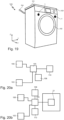
- a household appliance 100 in the form of a washing machine is shown.
- the household appliance 100 comprises a housing 101 and a tub 102 provided therein.
- the housing 101 comprises a front side, which has a closure device for the tub 102, a display and control panel and a detergent drawer.
- the filtration device 1 is provided in an upper area of a front side of the housing 101 and is thus easily accessible for a user. Possible arrangements are shown in Figure 19
- the household appliance 100 preferably comprises only one filtration device 1.
- the water-conducting household appliance 100 comprises a control device 105, which controls, among other things, the filtration device 1.
- the water-conducting household appliance 100 also comprises a pump device 103, which conveys water from the tub 102 to the at least one filtration device 1.
- a supply line is provided, which is connected to the supply line element 5.
- the discharge of the filtered water from the first drainage element 6 also takes place by means of the pump device 103.
- the control device 105 also controls the pump device 103, as shown in the schematic diagram in Figures 20a and 20b
- the first drain element 6 is fluidically connected to the drain 104 of the water-conducting household appliance 100 and/or the suds container 102 by means of a first drain line.
- the second drain element 7 is connected to a drain 104 of the water-conducting household appliance 100 via a bypass line.
- An additional pump device 108 is provided in the second drain element 7 and/or in the bypass line, by means of which the water can be conveyed from the second drain element 7 or the filter element 3 or the filtration device 1.
- the additional pumping device 108 is not activated, so that no water can be drained via the second drainage element 7.
- the filtered water is therefore advantageously drained only via the first drainage element 6 during the pumping process.
- the additional pumping device 108 is activated.
- the filtered water can advantageously be drained only via the second drainage element 7, since drainage via the first drainage element 6 no longer occurs.
- At least one first sensor device 106 can be provided, by means of which an emptying requirement of the filtration device 1 can be detected.
- This sensor device 106 can be designed in a variety of ways, for example a flow sensor can be provided which detects the flow through the second drainage element 7 and/or the drainage connected thereto. This could be the case in the embodiment according to the Figures 1 to 11b be useful.
- An optical sensor 106 could be provided which detects the amount of microplastic particles and fibers 20 in the second outer element 19.
- the control device 105 Upon detection of the need for emptying, transmits a command to an indication device 110, which issues an indication to the user.
- FIG 20a A schematic diagram is shown, which for the embodiment according to the Figures 1 to 11b could be given.
- Figure 20b A schematic diagram is shown, which for the embodiment according to the Figures 12 to 18 could be given.
- the control device 105 also controls the drive device 21. This preferably takes place after the pumping process has ended, and advantageously after the remaining water has exited through the second drainage element 7.
- the control device 105 preferably controls the drive device 21 in such a way that a predetermined number of rotations of the helical inner element 10, 17 are carried out.
- the filtration device 1 achieves effective filtering of microplastic particles and fibers 20. Furthermore, the easy cleaning option of the filtration device 1 eliminates the need for time-consuming replacement of microplastic filters.
Landscapes
- Chemical & Material Sciences (AREA)
- Chemical Kinetics & Catalysis (AREA)
- Engineering & Computer Science (AREA)
- Life Sciences & Earth Sciences (AREA)
- Hydrology & Water Resources (AREA)
- Environmental & Geological Engineering (AREA)
- Water Supply & Treatment (AREA)
- Organic Chemistry (AREA)
- Textile Engineering (AREA)
- Filtering Materials (AREA)
- Water Treatment By Sorption (AREA)
Applications Claiming Priority (1)
| Application Number | Priority Date | Filing Date | Title |
|---|---|---|---|
| DE102023103570.3A DE102023103570B3 (de) | 2023-02-14 | 2023-02-14 | Filtrationseinrichtung für ein wasserführendes Haushaltsgerät |
Publications (1)
| Publication Number | Publication Date |
|---|---|
| EP4417290A1 true EP4417290A1 (fr) | 2024-08-21 |
Family
ID=89772061
Family Applications (1)
| Application Number | Title | Priority Date | Filing Date |
|---|---|---|---|
| EP24154762.9A Pending EP4417290A1 (fr) | 2023-02-14 | 2024-01-30 | Dispositif de filtration pour un appareil ménager à circulation d'eau |
Country Status (4)
| Country | Link |
|---|---|
| US (1) | US12534388B2 (fr) |
| EP (1) | EP4417290A1 (fr) |
| CN (1) | CN118491188A (fr) |
| DE (1) | DE102023103570B3 (fr) |
Families Citing this family (3)
| Publication number | Priority date | Publication date | Assignee | Title |
|---|---|---|---|---|
| US12427453B2 (en) * | 2022-11-25 | 2025-09-30 | Samsung Electronics Co., Ltd. | Microplastic filter for washing machines or other appliances |
| DE102024110493A1 (de) * | 2024-04-15 | 2025-10-16 | Grohe Ag | Sanitärarmatur und Verfahren zum Betrieb der Sanitärarmatur |
| WO2026044136A1 (fr) * | 2024-08-21 | 2026-02-26 | Cleanr Inc. | Dispositif de raclage pour système de filtration à écoulement transversal tourbillonnaire |
Citations (4)
| Publication number | Priority date | Publication date | Assignee | Title |
|---|---|---|---|---|
| US20100084324A1 (en) * | 2005-12-02 | 2010-04-08 | Heinz Geisbauer | Cleaning apparatus |
| US20200230530A1 (en) * | 2019-01-18 | 2020-07-23 | Spiral Water Technologies, Inc. | Plant trichome filtration and concentration |
| US20200316501A1 (en) * | 2017-12-19 | 2020-10-08 | Xeros Limited | Filter for a treatment apparatus |
| US20220008845A1 (en) * | 2018-10-31 | 2022-01-13 | Ufi Innovation Center S.R.L. | Washing machine with filter group |
Family Cites Families (6)
| Publication number | Priority date | Publication date | Assignee | Title |
|---|---|---|---|---|
| US11066771B2 (en) | 2017-10-25 | 2021-07-20 | E.G.O. Elektro-Geraetebau Gmbh | Method for operating a washing machine and washing machine |
| CN112210967A (zh) | 2019-07-10 | 2021-01-12 | 合肥航亿科技有限公司 | 毛绒收集装置及其洗衣机 |
| DE102020200685A1 (de) | 2020-01-22 | 2021-07-22 | BSH Hausgeräte GmbH | Wasserführendes Haushaltsgerät |
| TR202007084A2 (tr) | 2020-05-06 | 2021-11-22 | Vestel Beyaz Esya San Ve Tic A S | Mikrofiber filtre tertibatı içeren yıkayıcı cihaz. |
| GB2595947B (en) | 2020-12-04 | 2022-11-02 | Xeros Ltd | A filter unit, a textile treatment apparatus, use thereof and a method of filtering microparticles |
| IT202100023561A1 (it) | 2021-09-13 | 2023-03-13 | Elbi Int Spa | Sistema filtrante, in particolare per una macchina lavatrice o asciugatrice, quale una lavabiancheria o un asciugatore. |
-
2023
- 2023-02-14 DE DE102023103570.3A patent/DE102023103570B3/de active Active
-
2024
- 2024-01-30 EP EP24154762.9A patent/EP4417290A1/fr active Pending
- 2024-02-14 US US18/441,056 patent/US12534388B2/en active Active
- 2024-02-18 CN CN202410180958.7A patent/CN118491188A/zh active Pending
Patent Citations (4)
| Publication number | Priority date | Publication date | Assignee | Title |
|---|---|---|---|---|
| US20100084324A1 (en) * | 2005-12-02 | 2010-04-08 | Heinz Geisbauer | Cleaning apparatus |
| US20200316501A1 (en) * | 2017-12-19 | 2020-10-08 | Xeros Limited | Filter for a treatment apparatus |
| US20220008845A1 (en) * | 2018-10-31 | 2022-01-13 | Ufi Innovation Center S.R.L. | Washing machine with filter group |
| US20200230530A1 (en) * | 2019-01-18 | 2020-07-23 | Spiral Water Technologies, Inc. | Plant trichome filtration and concentration |
Also Published As
| Publication number | Publication date |
|---|---|
| US20240270604A1 (en) | 2024-08-15 |
| US12534388B2 (en) | 2026-01-27 |
| DE102023103570B3 (de) | 2024-03-28 |
| CN118491188A (zh) | 2024-08-16 |
Similar Documents
| Publication | Publication Date | Title |
|---|---|---|
| DE102023103570B3 (de) | Filtrationseinrichtung für ein wasserführendes Haushaltsgerät | |
| EP1919346B1 (fr) | Lave-vaisselle, notamment lave-vaisselle menager et procede d'utilisation associe | |
| DE69618861T2 (de) | Geschirrspülmaschine mit Filtereinrichtung und -verfahren | |
| DE60206490T2 (de) | Geschirrspülmaschine mit durch den Spülwasserstrom rotierbarer Filter- und Zerkleinerungsvorrichtung | |
| EP1835840B1 (fr) | Lave-vaisselle à plusieurs cuves, équipé d'un dispositif de lavage à contre-courant | |
| DE4131914C2 (de) | Siebkombination für Haushalt-Geschirrspülmaschinen | |
| EP2205140B1 (fr) | Appareil ménager à circulation d'eau doté d'un filtre autonettoyant | |
| DE8802328U1 (de) | Geschirrspülmaschine mit selbstreinigendem Umlaufsieb | |
| EP3854930B1 (fr) | Appareil électroménager à circulation d'eau comprenant une unité de filtration | |
| EP4119212B1 (fr) | Dispositif filtre pour un appareil électroménager à circulation d'eau, appareil électroménager à circulation d'eau doté d'un dispositif filtre et procédé de filtrage de l'eau à l'aide d'un dispositif filtre | |
| DE60025050T2 (de) | Waschmaschine mit einer Entleerungspumpe | |
| DE102007056919A1 (de) | Wasserführendes Haushaltsgerät | |
| DE10046349B4 (de) | Haushaltgerät | |
| DE102020213041A1 (de) | Abscheideeinrichtung einer Waschmaschine | |
| EP3663457B1 (fr) | Appareil électroménager conducteur d'eau et procédé de filtrage des fluides dans un appareil électroménager conducteur d'eau | |
| EP2559802B1 (fr) | Pompe à lessive dotée d'une installation de filtre pour un lave-linge | |
| EP4249667A1 (fr) | Appareil de traitement du linge | |
| EP4417287A1 (fr) | Dispositif de filtration pour un appareil ménager à circulation d'eau | |
| EP3866663B1 (fr) | Lave-vaisselle ménager pourvu d'un système de filtre autonettoyant | |
| DE2947941C2 (de) | Waschmaschine | |
| DE102011084119A1 (de) | Flachsieb für eine Geschirrspülmaschine | |
| DE102018104538B4 (de) | Filter | |
| DE102024104033A1 (de) | Filtervorrichtung | |
| WO2025087843A1 (fr) | Lave-vaisselle domestique | |
| WO2025087769A1 (fr) | Lave-vaisselle domestique |
Legal Events
| Date | Code | Title | Description |
|---|---|---|---|
| PUAI | Public reference made under article 153(3) epc to a published international application that has entered the european phase |
Free format text: ORIGINAL CODE: 0009012 |
|
| STAA | Information on the status of an ep patent application or granted ep patent |
Free format text: STATUS: THE APPLICATION HAS BEEN PUBLISHED |
|
| AK | Designated contracting states |
Kind code of ref document: A1 Designated state(s): AL AT BE BG CH CY CZ DE DK EE ES FI FR GB GR HR HU IE IS IT LI LT LU LV MC ME MK MT NL NO PL PT RO RS SE SI SK SM TR |
|
| STAA | Information on the status of an ep patent application or granted ep patent |
Free format text: STATUS: REQUEST FOR EXAMINATION WAS MADE |
|
| 17P | Request for examination filed |
Effective date: 20250221 |
|
| STAA | Information on the status of an ep patent application or granted ep patent |
Free format text: STATUS: EXAMINATION IS IN PROGRESS |
|
| 17Q | First examination report despatched |
Effective date: 20250415 |