EP4417451A2 - Entraînement d'essieu à répartition de puissance et véhicule agricole - Google Patents
Entraînement d'essieu à répartition de puissance et véhicule agricole Download PDFInfo
- Publication number
- EP4417451A2 EP4417451A2 EP24180479.8A EP24180479A EP4417451A2 EP 4417451 A2 EP4417451 A2 EP 4417451A2 EP 24180479 A EP24180479 A EP 24180479A EP 4417451 A2 EP4417451 A2 EP 4417451A2
- Authority
- EP
- European Patent Office
- Prior art keywords
- power
- split
- transmission
- vehicle
- axle
- Prior art date
- Legal status (The legal status is an assumption and is not a legal conclusion. Google has not performed a legal analysis and makes no representation as to the accuracy of the status listed.)
- Granted
Links
Images







Classifications
-
- B—PERFORMING OPERATIONS; TRANSPORTING
- B60—VEHICLES IN GENERAL
- B60K—ARRANGEMENT OR MOUNTING OF PROPULSION UNITS OR OF TRANSMISSIONS IN VEHICLES; ARRANGEMENT OR MOUNTING OF PLURAL DIVERSE PRIME-MOVERS IN VEHICLES; AUXILIARY DRIVES FOR VEHICLES; INSTRUMENTATION OR DASHBOARDS FOR VEHICLES; ARRANGEMENTS IN CONNECTION WITH COOLING, AIR INTAKE, GAS EXHAUST OR FUEL SUPPLY OF PROPULSION UNITS IN VEHICLES
- B60K6/00—Arrangement or mounting of plural diverse prime-movers for mutual or common propulsion, e.g. hybrid propulsion systems comprising electric motors and internal combustion engines
- B60K6/20—Arrangement or mounting of plural diverse prime-movers for mutual or common propulsion, e.g. hybrid propulsion systems comprising electric motors and internal combustion engines the prime-movers consisting of electric motors and internal combustion engines, e.g. HEVs
- B60K6/50—Architecture of the driveline characterised by arrangement or kind of transmission units
- B60K6/52—Driving a plurality of drive axles, e.g. four-wheel drive
-
- B—PERFORMING OPERATIONS; TRANSPORTING
- B60—VEHICLES IN GENERAL
- B60K—ARRANGEMENT OR MOUNTING OF PROPULSION UNITS OR OF TRANSMISSIONS IN VEHICLES; ARRANGEMENT OR MOUNTING OF PLURAL DIVERSE PRIME-MOVERS IN VEHICLES; AUXILIARY DRIVES FOR VEHICLES; INSTRUMENTATION OR DASHBOARDS FOR VEHICLES; ARRANGEMENTS IN CONNECTION WITH COOLING, AIR INTAKE, GAS EXHAUST OR FUEL SUPPLY OF PROPULSION UNITS IN VEHICLES
- B60K6/00—Arrangement or mounting of plural diverse prime-movers for mutual or common propulsion, e.g. hybrid propulsion systems comprising electric motors and internal combustion engines
- B60K6/20—Arrangement or mounting of plural diverse prime-movers for mutual or common propulsion, e.g. hybrid propulsion systems comprising electric motors and internal combustion engines the prime-movers consisting of electric motors and internal combustion engines, e.g. HEVs
- B60K6/22—Arrangement or mounting of plural diverse prime-movers for mutual or common propulsion, e.g. hybrid propulsion systems comprising electric motors and internal combustion engines the prime-movers consisting of electric motors and internal combustion engines, e.g. HEVs characterised by apparatus, components or means specially adapted for HEVs
- B60K6/36—Arrangement or mounting of plural diverse prime-movers for mutual or common propulsion, e.g. hybrid propulsion systems comprising electric motors and internal combustion engines the prime-movers consisting of electric motors and internal combustion engines, e.g. HEVs characterised by apparatus, components or means specially adapted for HEVs characterised by the transmission gearings
- B60K6/365—Arrangement or mounting of plural diverse prime-movers for mutual or common propulsion, e.g. hybrid propulsion systems comprising electric motors and internal combustion engines the prime-movers consisting of electric motors and internal combustion engines, e.g. HEVs characterised by apparatus, components or means specially adapted for HEVs characterised by the transmission gearings with the gears having orbital motion
-
- B—PERFORMING OPERATIONS; TRANSPORTING
- B60—VEHICLES IN GENERAL
- B60K—ARRANGEMENT OR MOUNTING OF PROPULSION UNITS OR OF TRANSMISSIONS IN VEHICLES; ARRANGEMENT OR MOUNTING OF PLURAL DIVERSE PRIME-MOVERS IN VEHICLES; AUXILIARY DRIVES FOR VEHICLES; INSTRUMENTATION OR DASHBOARDS FOR VEHICLES; ARRANGEMENTS IN CONNECTION WITH COOLING, AIR INTAKE, GAS EXHAUST OR FUEL SUPPLY OF PROPULSION UNITS IN VEHICLES
- B60K6/00—Arrangement or mounting of plural diverse prime-movers for mutual or common propulsion, e.g. hybrid propulsion systems comprising electric motors and internal combustion engines
- B60K6/20—Arrangement or mounting of plural diverse prime-movers for mutual or common propulsion, e.g. hybrid propulsion systems comprising electric motors and internal combustion engines the prime-movers consisting of electric motors and internal combustion engines, e.g. HEVs
- B60K6/22—Arrangement or mounting of plural diverse prime-movers for mutual or common propulsion, e.g. hybrid propulsion systems comprising electric motors and internal combustion engines the prime-movers consisting of electric motors and internal combustion engines, e.g. HEVs characterised by apparatus, components or means specially adapted for HEVs
- B60K6/38—Arrangement or mounting of plural diverse prime-movers for mutual or common propulsion, e.g. hybrid propulsion systems comprising electric motors and internal combustion engines the prime-movers consisting of electric motors and internal combustion engines, e.g. HEVs characterised by apparatus, components or means specially adapted for HEVs characterised by the driveline clutches
- B60K6/387—Actuated clutches, i.e. clutches engaged or disengaged by electric, hydraulic or mechanical actuating means
-
- B—PERFORMING OPERATIONS; TRANSPORTING
- B60—VEHICLES IN GENERAL
- B60K—ARRANGEMENT OR MOUNTING OF PROPULSION UNITS OR OF TRANSMISSIONS IN VEHICLES; ARRANGEMENT OR MOUNTING OF PLURAL DIVERSE PRIME-MOVERS IN VEHICLES; AUXILIARY DRIVES FOR VEHICLES; INSTRUMENTATION OR DASHBOARDS FOR VEHICLES; ARRANGEMENTS IN CONNECTION WITH COOLING, AIR INTAKE, GAS EXHAUST OR FUEL SUPPLY OF PROPULSION UNITS IN VEHICLES
- B60K6/00—Arrangement or mounting of plural diverse prime-movers for mutual or common propulsion, e.g. hybrid propulsion systems comprising electric motors and internal combustion engines
- B60K6/20—Arrangement or mounting of plural diverse prime-movers for mutual or common propulsion, e.g. hybrid propulsion systems comprising electric motors and internal combustion engines the prime-movers consisting of electric motors and internal combustion engines, e.g. HEVs
- B60K6/42—Arrangement or mounting of plural diverse prime-movers for mutual or common propulsion, e.g. hybrid propulsion systems comprising electric motors and internal combustion engines the prime-movers consisting of electric motors and internal combustion engines, e.g. HEVs characterised by the architecture of the hybrid electric vehicle
- B60K6/48—Parallel type
-
- B—PERFORMING OPERATIONS; TRANSPORTING
- B60—VEHICLES IN GENERAL
- B60K—ARRANGEMENT OR MOUNTING OF PROPULSION UNITS OR OF TRANSMISSIONS IN VEHICLES; ARRANGEMENT OR MOUNTING OF PLURAL DIVERSE PRIME-MOVERS IN VEHICLES; AUXILIARY DRIVES FOR VEHICLES; INSTRUMENTATION OR DASHBOARDS FOR VEHICLES; ARRANGEMENTS IN CONNECTION WITH COOLING, AIR INTAKE, GAS EXHAUST OR FUEL SUPPLY OF PROPULSION UNITS IN VEHICLES
- B60K6/00—Arrangement or mounting of plural diverse prime-movers for mutual or common propulsion, e.g. hybrid propulsion systems comprising electric motors and internal combustion engines
- B60K6/20—Arrangement or mounting of plural diverse prime-movers for mutual or common propulsion, e.g. hybrid propulsion systems comprising electric motors and internal combustion engines the prime-movers consisting of electric motors and internal combustion engines, e.g. HEVs
- B60K6/42—Arrangement or mounting of plural diverse prime-movers for mutual or common propulsion, e.g. hybrid propulsion systems comprising electric motors and internal combustion engines the prime-movers consisting of electric motors and internal combustion engines, e.g. HEVs characterised by the architecture of the hybrid electric vehicle
- B60K6/48—Parallel type
- B60K2006/4808—Electric machine connected or connectable to gearbox output shaft
-
- B—PERFORMING OPERATIONS; TRANSPORTING
- B60—VEHICLES IN GENERAL
- B60K—ARRANGEMENT OR MOUNTING OF PROPULSION UNITS OR OF TRANSMISSIONS IN VEHICLES; ARRANGEMENT OR MOUNTING OF PLURAL DIVERSE PRIME-MOVERS IN VEHICLES; AUXILIARY DRIVES FOR VEHICLES; INSTRUMENTATION OR DASHBOARDS FOR VEHICLES; ARRANGEMENTS IN CONNECTION WITH COOLING, AIR INTAKE, GAS EXHAUST OR FUEL SUPPLY OF PROPULSION UNITS IN VEHICLES
- B60K23/00—Arrangement or mounting of control devices for vehicle transmissions, or parts thereof, not otherwise provided for
- B60K23/08—Arrangement or mounting of control devices for vehicle transmissions, or parts thereof, not otherwise provided for for changing number of driven wheels, for switching from driving one axle to driving two or more axles
-
- B—PERFORMING OPERATIONS; TRANSPORTING
- B60—VEHICLES IN GENERAL
- B60K—ARRANGEMENT OR MOUNTING OF PROPULSION UNITS OR OF TRANSMISSIONS IN VEHICLES; ARRANGEMENT OR MOUNTING OF PLURAL DIVERSE PRIME-MOVERS IN VEHICLES; AUXILIARY DRIVES FOR VEHICLES; INSTRUMENTATION OR DASHBOARDS FOR VEHICLES; ARRANGEMENTS IN CONNECTION WITH COOLING, AIR INTAKE, GAS EXHAUST OR FUEL SUPPLY OF PROPULSION UNITS IN VEHICLES
- B60K6/00—Arrangement or mounting of plural diverse prime-movers for mutual or common propulsion, e.g. hybrid propulsion systems comprising electric motors and internal combustion engines
- B60K6/20—Arrangement or mounting of plural diverse prime-movers for mutual or common propulsion, e.g. hybrid propulsion systems comprising electric motors and internal combustion engines the prime-movers consisting of electric motors and internal combustion engines, e.g. HEVs
- B60K6/42—Arrangement or mounting of plural diverse prime-movers for mutual or common propulsion, e.g. hybrid propulsion systems comprising electric motors and internal combustion engines the prime-movers consisting of electric motors and internal combustion engines, e.g. HEVs characterised by the architecture of the hybrid electric vehicle
- B60K6/44—Series-parallel type
- B60K6/442—Series-parallel switching type
-
- B—PERFORMING OPERATIONS; TRANSPORTING
- B60—VEHICLES IN GENERAL
- B60Y—INDEXING SCHEME RELATING TO ASPECTS CROSS-CUTTING VEHICLE TECHNOLOGY
- B60Y2200/00—Type of vehicle
- B60Y2200/20—Off-Road Vehicles
- B60Y2200/22—Agricultural vehicles
- B60Y2200/221—Tractors
-
- B—PERFORMING OPERATIONS; TRANSPORTING
- B60—VEHICLES IN GENERAL
- B60Y—INDEXING SCHEME RELATING TO ASPECTS CROSS-CUTTING VEHICLE TECHNOLOGY
- B60Y2200/00—Type of vehicle
- B60Y2200/90—Vehicles comprising electric prime movers
- B60Y2200/92—Hybrid vehicles
Definitions
- the invention relates to a power-split axle drive according to the preamble of independent claim 1 and an agricultural vehicle according to the preamble of independent claim 11 and a method for operating a power-split axle drive according to the preamble of independent claim 14.
- the EN 10 2007 021 732 A1 discloses a power-split axle drive for vehicles with at least two drivable vehicle axles, in particular for commercial vehicles and agricultural vehicles.
- the power-split axle drive has a continuously variable transmission without an inter-axle differential with at least a first and a second motor.
- the first motor is connected to a first vehicle axle and the second motor is connected to a second vehicle axle.
- the power-split axle drive also has a clutch.
- the clutch can be used to establish a connection between the first and the second vehicle axle.
- the torque transmission capacity of the clutch can be adjusted depending on the drive state of the vehicle. From the EP 3 626 502 A1 An agricultural vehicle with a power-split axle drive is known.
- the power-split axle drive comprises a partial drive train with an additional drive element, an electric motor.
- the electric motor can be optionally connected to the power-split axle drive by means of a controllable torque transmission device.
- the EN 10 2013 224 383 A1 discloses a power-split axle drive with a power-split transmission and an additional drive element. Both the EP 3 626 502 A1 , as well as the EN 10 2013 224 383 A1 disclose that the additional drive element acts on the power split transmission in such a way that a forward travel of a vehicle axle can be controlled.
- the known power-split axle drives have the disadvantage of a complex construction and/or inadequate for agricultural vehicles.
- the speed and/or power and/or torque of the additional drive, in particular of the electric motors used for this purpose is too high and thus the speed and/or torque transmitted to the power-split axle drive is too small.
- Another disadvantage is that efficient braking cannot be achieved with the known power-split axle drives.
- the present invention is therefore based on the object of proposing a power-split axle drive and an agricultural vehicle as well as a method by which the aforementioned problems are overcome.
- a power-split axle drive and an agricultural vehicle as well as a method are to be proposed which are structurally simpler and/or less complex and/or enable efficient transmission of the speed and/or torque from the auxiliary drive to the power-split transmission and/or enable more efficient operation and/or the performance and/or drivability and/or driving characteristics of the commercial vehicle or the power-split axle drive are improved.
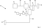
- a power-split axle drive in particular a drive train, is proposed for an agricultural vehicle.
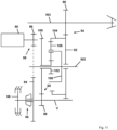
- the power-split axle drive comprises a first additional drive element and a first vehicle axle and a second vehicle axle and a main drive element for providing a torque and/or in particular a rotary movement and/or a force.
- the torque, and/or in particular the rotary movement and/or the force can be transmitted to a main transmission with a first shaft and/or introduced into the main transmission.
- the main transmission is therefore connected to the main drive element via or with the first shaft, in particular is drivably connected.
- the second vehicle axle is connected to the main transmission, in particular is drivably connected.
- At least the second vehicle axle can be driven with the torque, and/or in particular the rotary movement and/or the force, of the main drive element with or via the main transmission.
- the second vehicle axle is connected to the main transmission via or with a third shaft, in particular is drivably connected.
- a torque, and/or in particular a rotary movement and/or a force can be generated by the main drive element, which can be introduced or transmitted into the main transmission with the first or via the first shaft and from the main transmission with the third or via the third shaft into or to the second vehicle axle.
- the power-split axle drive further comprises a power-split transmission.
- the power-split transmission is connected, in particular drivably connected, to the main transmission and the second vehicle axle via or with a first gear set.
- a rotary motion and/or a force and/or a torque can be transmitted or introduced from the main drive element to the main transmission and from the main transmission with or via the first gear set to or into the power-split transmission and/or vice versa.
- a rotary motion and/or a force and/or a torque can be transmitted or introduced from the second vehicle axle with or via the first gear set to or into the power-split transmission and/or vice versa.
- the first vehicle axle is connected, in particular drivably connected, to the power-split transmission via or with a second shaft.
- a torque, and/or in particular a rotary motion and/or a force, of the power-split transmission can be transmitted or introduced via the second shaft to or into the first vehicle axle and/or vice versa.
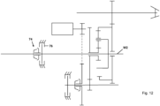
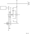
- the first The additional drive element is connectable, preferably detachably connectable, particularly preferably detachably non-rotatably and/or detachably drivable, to the power split transmission via a first or with a first switching element, in particular for initiating a rotary movement and/or a force and/or a torque.
- the power split transmission can be connected to the third shaft via or with the first gear set, in particular can be connected in a driveable manner.
- a rotary motion and/or a force and/or a torque can be transmitted or introduced from the main drive element to the main transmission and from the main transmission to the third shaft and with or via the first gear set from the third shaft to or into the power split transmission.
- a rotary motion and/or a force and/or a torque can be transmitted or introduced from the second vehicle axle to the third shaft and with or via the first gear set from the third shaft to or into the power split transmission.
- the first gear set can also comprise a first gear pair, in particular a first and a second fixed gear.
- the first fixed gear can be connected to the third shaft and the second fixed gear to the power split transmission, preferably connected in a rotationally fixed manner.
- the first fixed gear can mesh with the second fixed gear, i.e. in particular can be in constant meshing engagement with it.
- a rotary motion and/or a force and/or a torque can be transmitted or introduced between the third shaft and the power split transmission with or via the first and second fixed gear and/or vice versa.
- the power-split axle drive can comprise a first differential, in particular a front axle differential.
- the first differential can be connected to the power-split transmission via the second or with the second shaft, in particular can be connected in a drivable manner.
- a rotary movement and/or a force and/or a torque of the power-split transmission can be transmitted to or from the first vehicle axle via the first differential. and/or vice versa.
- the power-split axle drive can also comprise a second differential, in particular a rear axle differential.
- the second differential can be connected to the main transmission via the third or with the third shaft, in particular can be drivably connected.
- a rotary movement and/or a force and/or a torque of the main transmission can be introduced or transmitted with or via the second differential into or to the second vehicle axle and/or vice versa.
- the first switching element can be actuated, preferably selectively actuated, particularly preferably lockable and openable and/or engageable and/or switchable and/or selectively engageable.
- the first switching element can be designed as a first clutch.
- a switching element preferably the first switching element and/or a second and/or third and/or fourth and/or fifth switching element, can be understood as a component which, depending on the actuation state, can allow a relative movement between two components or can provide a fixed connection for transmitting a rotary movement and/or a force and/or a torque.
- a relative movement is to be understood as, for example, a rotation of two components, wherein the speed of the first component and the speed of the second component differ from one another.
- the switching elements are preferably frictionally engaged elements.
- a force can be introduced via an actuator onto the connection point of the two components, creating a frictional force through which a rotary movement and/or a force and/or a torque can be transmitted between the two rotary components.
- a non-actuated switching element in particular a non-actuated clutch, can be understood as an open switching element, in particular an open clutch. This means that a relative movement between the two components is possible.
- An actuated switching element in particular an actuated Clutch can be understood below as a closed switching element, in particular a closed clutch. This means that no relative movement is possible between the two components. The two components therefore rotate at the same speed in the same direction.
- the switching elements, in particular clutches can be designed as form-fitting elements.
- the actuator for actuating the first switching element, in particular the first clutch can be designed to be hydraulically, electromechanically, electromagnetically or, for example, pneumatically actuated.
- the actuator in particular a first actuator, can close and open the first switching element and/or a second actuator can close and open the second switching element and/or a third actuator can close and open the third switching element and/or a fourth actuator can close and open the fourth switching element and/or a fifth actuator can close and open the fifth switching element.
- a rotary movement and/or a force and/or a torque can be transmitted from the first additional drive element to the power split transmission and/or vice versa.
- the first switching element not actuated, in particular opened no rotary movement and/or no force and/or no torque can be transmitted from the first additional drive element to the power split transmission.
- the first additional drive element can be connected to the power split transmission with the closed first switching element in such a way that the power split transmission can be driven with the first additional drive element.
- the first additional drive element can therefore act on the power split transmission in such a way that a lead of the first vehicle axle can be regulated, in particular also set and/or adjusted.
- the main drive element is preferably an internal combustion engine, for example an engine powered by gas, petrol or diesel fuel.
- the main drive element can also be implemented in the form of an electric machine.
- the additional drive element is preferably an electrical machine, for example an electric motor.
- a design in the form of a hydraulic drive, for example a hydrostatic drive element is also conceivable.
- the first additional drive element can have two directions of rotation (first direction, second direction). The two directions of rotation of the first additional drive element can be used to achieve a larger control range of the advance of the first vehicle axle.
- the first vehicle axle and the second vehicle axle are vehicle axles that can be designed to be drivable.
- the first vehicle axle and/or the second vehicle axle can be designed to be steerable, preferably only the first vehicle axle.
- the first vehicle axle can be a front axle and/or the second vehicle axle can be a rear axle.
- the main transmission is preferably characterized in that a transmission of the speed and/or the force and/or the torque takes place from a transmission input to a transmission output.
- the transmission input is arranged on a side of the main transmission that preferably faces the main drive element.
- the transmission output is preferably located on a side of the main transmission opposite the transmission input.
- the main transmission can be designed, for example, as a stepped automatic transmission or as a continuously variable transmission, in particular as a CVT (Continuously Variable Transmission) or as an elVT (Electrical Infinitely Variable Transmission) or as an hIVT (Hydraulic Infinitely Variable Transmission), or as a manual transmission or even as a dual-clutch transmission.
- CVT Continuous Variable Transmission
- elVT ElectromV
- hIVT Hydraulic Infinitely Variable Transmission
- a shaft is not only understood to mean a cylindrical, rotatably mounted machine element for transmitting torque, but rather also general connecting elements that connect individual components or elements to one another.
- the respective components are connected by the first, second and third shaft and the countershaft are mechanically connected to each other. This means that rotational movements and/or forces and/or torques can be transmitted through the first, second and third shafts and the countershaft.
- the power split transmission is preferably a planetary transmission or epicyclic transmission.
- a planetary transmission can have at least three components, in particular gears and/or shafts.
- a component can be understood as an input and/or output for transmitting a rotary motion and/or force and/or torque into and/or out of the power split transmission.
- the planetary transmission works as a summation transmission or as a transfer transmission. In the summation transmission, two components are designed to be driving and one component is driven. In contrast, in a transfer transmission, one component is designed to be driving and two components are driven.
- a control device can be assigned to the power-split axle drive or the power-split axle drive can comprise the control device.
- the control device can be connected to the power-split axle drive, in particular to the components of the power-split axle drive, preferably connected in a signal-connected and/or signal-transmitting and/or data-conducting manner.
- the control device can be used to control and/or regulate and/or actuate the interconnected components.
- the advance of the first vehicle axle is regulated in this way, for example taking into account a currently applied steering angle or a speed or a torque of the main drive element and/or the first and/or second vehicle axle. during cornering and/or a speed and/or a torque.
- a steering angle can be understood as an angle of the wheels of a steerable axle to the wheels of a non-steerable axle or to a longitudinal axis of a vehicle.
- Controlling the lead of the first vehicle axle depending on a steering angle of one of the vehicle axles or both vehicle axles to each other can be understood to mean that a change in the steering angle is also accompanied by a change in the lead of the first vehicle axle.
- the lead can be increased or reduced as required.
- the change in the lead can, however, also depend on further or other parameters, for example the nature of the ground or the weather conditions.
- a change in the lead can be automated by appropriate control and regulation or can be made manually by the operator using an input device. Arrangements are conceivable in which only one of the two vehicle axles is steerable or in which both vehicle axles are steerable, for example in the form of all-wheel steering.
- the first additional drive element can be operated as a generator or as a motor.
- generator mode the first additional drive element has a braking effect, which means that mechanical energy from a rotary movement and/or a force and/or a torque is converted into electrical energy, for example.
- motor mode of the first additional drive element energy, in particular electrical energy, can be fed into the first additional drive element, whereby the additional drive element generates a rotary movement and/or a force and/or a torque and the first additional drive element has a driving or propulsive effect.
- the first additional drive element can preferably be operated as a motor.
- the power-split axle drive can also include a storage element.
- the storage element is characterized in particular by the fact that it can absorb energy, store energy and release energy.
- the storage element is preferably a battery, an accumulator or a Capacitor for storing electrical energy. In other designs, however, pressure accumulators for storing compressed gases or fluids or kinetic energy storage are also conceivable. In a kinetic energy storage device, kinetic energy is stored in rotating masses, for example.
- the first additional drive element can be connected to the storage element via a connecting line using power electronics.
- a power electronic connection can be understood to mean that generated electrical energy or stored electrical energy can be supplied to or removed from the storage element or supplied to consumers, for example the first additional drive element, via the connecting line.
- the storage element is optionally provided.
- the electrical energy provided by the storage element can be used by the first auxiliary drive element to motor-operate the first auxiliary drive element in order to increase the advance of the first vehicle axle.
- the main drive element can introduce a rotary motion and/or a force and/or a torque into the main transmission via the first or with the first shaft.
- the rotary motion and/or a force and/or a torque introduced into the main transmission is translated in the main transmission as long as a gear or a drive position is engaged.
- the rotary motion and/or the force and/or the torque present when a gear or drive position is engaged can be introduced into the second vehicle axle at the transmission output of the main transmission via the third shaft.
- the Rotational movement and/or the power and/or the torque of the main drive element are introduced or transmitted via the main transmission from the third shaft via the first gear set into the power split transmission.
- One or more operating modes can be implemented with the power-split axle drive, in particular also with the agricultural vehicle.
- the control device can be designed or set up in particular to regulate and/or control and/or activate one or more operating modes of the power-split axle drive or agricultural vehicle.
- a "generator" operating mode of the power-split axle drive or vehicle can be implemented, in particular in a driving or overrun mode of the power-split axle drive and/or the agricultural vehicle, for example for charging the storage element.
- the first additional drive element can be operated as a generator.
- a rotary movement and/or a force and/or a torque can be introduced or transmitted into the power-split transmission and from the power-split transmission into or to the first additional drive element using the main drive element.
- the rotary motion and/or the force and/or the torque introduced into the first additional drive element can be converted into electrical energy by the first additional drive element and the electrical energy can be stored in the storage element.
- the storage element is optional in this arrangement; only the recuperation just described, particularly in the "generator" operating mode of the vehicle, is omitted due to the generator operation of the first additional drive element.
- the ground engagement means in particular wheels or tracks, can cover a greater distance than the ground engagement means, in particular wheels or crawlers, the second vehicle axle of the vehicle.
- a constant speed ratio is set between the first and second vehicle axles of the vehicle.
- a structural advance is provided in the vehicle. This means that, for example, the ground engagement means of the first vehicle axle have a higher peripheral speed than those of the second vehicle axle.
- a "advance" operating mode of the power-split axle drive and/or the agricultural vehicle can be implemented, in particular in a driving or pushing operation of the axle drive and/or the vehicle and/or a journey of the vehicle on a field, for example when working the field or accompanying a harvester as a tractor with a transport wagon.
- the first additional drive element can be operated by a motor.
- an additional rotary movement and/or an additional force and/or an additional torque of the first auxiliary drive element can be transmitted from the first auxiliary drive element to the power split transmission with the first switching element.
- the rotary movement and/or force and/or the transmitted torque of the main drive element transmitted to the power split transmission and the additional rotary movement and/or force and/or the transmitted additional torque of the first auxiliary drive element transmitted to the power split transmission can be superimposed with the power split transmission and a resulting rotary movement and/or a resulting force and/or a resulting torque can be transmitted to the first vehicle axle, in particular with or via the first differential.
- a lead of the first vehicle axle can thus be set and/or adjusted, in particular controllable and/or regulated.
- the first auxiliary drive element acts with the first switching element closed and in motor operation on the power split transmission in such a way that the first additional drive element introduces a rotary movement and/or a force and/or a torque into the power split transmission, which is superimposed on a rotary movement and/or force and/or an introduced torque introduced into the power split transmission by the main drive element via the main transmission, so that a lead of the first vehicle axle can be set and/or adjusted with the resulting rotary movement and/or force and/or the resulting torque.
- the change in the lead can advantageously bring about a change in the peripheral speed of the ground engagement means, preferably wheels or tracks, on the first vehicle axle, in particular an increase in the peripheral speed or a reduction in the peripheral speed of the ground engagement means on the first vehicle axle.
- An increase in the lead of the first vehicle axle is to be understood as meaning that the speed of the first vehicle axle or the peripheral speed of the ground engagement means of the first vehicle axle is further increased in comparison to the second vehicle axle.
- a reduction in the advance of the first vehicle axle means that the speed of the first vehicle axle or the circumferential speed of the ground engagement means of the first vehicle axle is reduced in comparison to the second vehicle axle.
- a change in the advance of the first vehicle axle can take place in this way.
- the "generator" operating mode can be active at a first steering angle, i.e. the first additional drive element generates electrical power, and at a second steering angle, which can be greater than the first steering angle, the "advance" operating mode can be active, i.e. in particular the first additional drive element consumes electrical power and transmits a speed and/or a force and/or a torque to the power-split axle drive.
- the first steering angle can cover a range from 0 degrees to 4 degrees, preferably from 0 to 8 degrees, particularly preferably in a range from 0 to 12 degrees.
- the second steering angle can have a range >4 degrees, preferably >8 degrees, particularly preferably > 12 degrees.
- the steering assistance comes into effect by switching on the first additional drive element, i.e. by changing, in particular by increasing or reducing, the speed and/or power and/or torque on the first vehicle axle, which is particularly advantageous when cornering tightly on the headland of a field in order to be able to negotiate smaller curve radii.
- the axle speeds of the first vehicle axle and the second vehicle axle are set as in an all-wheel drive system with an open longitudinal differential or with an open all-wheel drive clutch or a vehicle driven only on one axle (here the second vehicle axle). In this state, the first additional drive element is then in freewheel mode.
- the first additional drive element can be selectively connected to the first or, via the first switching element, to the power split transmission, so that an additional rotary movement and/or an additional force and/or an additional torque can be transmitted to the power split transmission with the first additional drive element.
- the speed and/or force and/or the torque transmitted by the power split axle drive to the first vehicle axle can be increased compared to the speed and/or force and/or the torque provided by the power split axle drive on the second vehicle axle, so that steering assistance is possible when cornering tightly, in particular on the headland of a field driven by the agricultural vehicle.
- a control and/or Control in particular by speed and/or torque control, of the first additional drive element, for example with the control device, can advantageously represent a longitudinal differential function with variable torque distribution between the first vehicle axle and the second vehicle axle.
- Input data for this can be, for example, the speed or the torque on the main drive element and/or the vehicle axles. This can improve the traction of the vehicle depending on the situation.
- a longitudinal differential function with constant torque distribution can be represented.
- the driving characteristics of the vehicle can be specifically controlled and adapted to the respective environmental conditions.
- a distribution of the braking power between the vehicle axles can also be realized during braking.
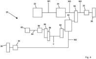
- the power-split axle drive comprises a countershaft.
- the first auxiliary drive element can be connected to the first or via the first shifting element to the countershaft, preferably drivably connected, particularly preferably detachably drivable connected.
- the power split transmission can be connected to the countershaft, in particular drivably connected.
- the power split transmission can thus be connected to the first auxiliary drive element via the countershaft, in particular drivably connected.
- the first auxiliary drive element can thus be connected to the countershaft with the first shifting element in such a way that the power split transmission can be driven with the first auxiliary drive element.
- the first shifting element can be arranged at least partially on or at the countershaft.
- the first shifting element can be connected at least partially to the countershaft in a rotationally fixed manner.
- a rotational movement and/or a force and/or a torque of the first auxiliary drive element can be transmitted to the first shifting element from the first
- the additional drive element can be transmitted to the countershaft and from the countershaft to the power split transmission.
- the power-split axle drive comprises a second and third gear set.
- the first shifting element can be connected or connected to the first auxiliary drive element via or with the second gear set, preferably can be connected or connected in a detachable manner, particularly preferably can be connected or connected in a detachable manner, and the countershaft is connected to the power-split transmission via the third gear set, preferably can be connected in a drivable manner.
- a rotary movement and/or a force and/or a torque of the first auxiliary drive element can be transmitted or introduced from the first auxiliary drive element to the first shifting element and/or vice versa and can be transmitted or introduced from the first shifting element further to or into the countershaft and/or vice versa, in particular when the first shifting element is closed.
- the countershaft in turn, can be connected to the first or via the first shifting element to the second gear set, preferably can be connected in a drivable manner, particularly preferably can be connected in a detachable manner.
- a rotary movement and/or a force and/or a torque can be transmitted from the first additional drive element to the second gear set and from the second gear set via the first or with the first shifting element to the countershaft and further to the power split transmission and/or vice versa.
- the power split transmission can be connected to the countershaft via or with the third gear set, in particular can be connected in a driveable manner.
- a rotary movement and/or a force and/or a torque of the countershaft can be transmitted or introduced to or into the power split transmission and/or vice versa.
- a rotary movement and/or a force and/or a Torque can be transmitted from the first additional drive element via the second gear set to the closed first shift element, then to the countershaft, and from the countershaft via the third gear set to the power split transmission, and from the power split transmission, in particular via the first differential, to the first vehicle axle.
- the second gear set can also comprise a second gear pair, in particular a first shift gear and a third fixed gear.
- the third fixed gear can be connected to the first additional drive element, in particular an output shaft of the first additional drive element, preferably connected in a drivable manner, particularly preferably connected in a rotationally fixed and/or drivable manner.
- the first shift gear can be rotatably mounted on the countershaft, in particular freely rotatable and/or axially displaceable on the countershaft.
- the first shift gear can be connected to one side of the first shift element, preferably connected in a rotationally fixed and/or drivable manner.
- the first shift gear can mesh with the third fixed gear, i.e. in particular be in constant meshing engagement with it.
- the first switching element can therefore be connected, preferably drivably connected, to the first auxiliary drive element via the first or with the first switching gear and via the third or with the third fixed gear.
- the countershaft in turn can be connected, preferably drivably connected, particularly preferably detachably drivable, to the first or with the first switching element via the first switching element.
- the countershaft When the first switching element is closed, the countershaft can be connected in a rotationally fixed manner to the first switching gear via the first switching element, so that a rotational movement and/or a force and/or a torque of the first auxiliary drive element can be transmitted via the third fixed gear.
- the first switching gear can have more gear teeth than the third fixed gear.
- the transmission ratio can be
- the third gear set can comprise a third gear pair, in particular a fourth and a fifth fixed gear.
- the fourth fixed gear can be connected to the countershaft V and the fifth fixed gear to the power split transmission, in particular a sun gear of the power split transmission, preferably connected in a rotationally fixed and/or drivable manner.
- the fourth fixed gear can mesh with the fifth fixed gear, i.e. in particular be in constant meshing engagement with it. With the fourth and fifth fixed gears, a rotary movement and/or a force and/or a torque can be transmitted from the countershaft to the power split transmission and/or vice versa.
- the fifth fixed gear can have more gear teeth than the fourth fixed gear.
- the gear ratio can be
- the speed transmitted from the first additional drive element to the power split transmission can be reduced and the transmitted torque increased. In this way, a transmission of the speed and/or the torque from the first additional drive to the power split transmission can be implemented and improved.
- a lead of the first vehicle axle can advantageously be set and/or adjusted more efficiently, in particular controlled and/or regulated more efficiently.
- the power split transmission is designed as Planetary gearing.
- a ring gear of the power split transmission can be connected to the third shaft via or with the first gear set, in particular connected in a drivable manner.
- the ring gear can be connected to the second fixed gear, preferably connected in a rotationally fixed and/or drivable manner.
- the first vehicle axle can be connected to a planet carrier or a web of the power split transmission via the second or with the second shaft, in particular connected in a drivable manner.
- the planet carrier can be connected to the second shaft, preferably connected in a rotationally fixed and/or drivable manner.
- a force and/or a rotary movement and/or a torque can be transmitted or introduced from the planet carrier of the power split transmission to the second shaft and further, in particular via the first differential, to or into the first vehicle axle.
- a force and/or a rotary movement and/or a torque can be transmitted or introduced into the power split transmission.
- a planetary gear set in particular one or more planetary gears, can be rotatably mounted on the planet carrier, each of which meshes with the sun gear and the ring gear, i.e. is in particular in constant meshing engagement with them.
- the planetary gear set can in particular have a set of planetary gears.
- the planetary gear set can comprise three planetary gears.
- the sun gear of the power split transmission is connected, in particular drivably connected, to the first additional drive element via the fifth fixed gear and the fourth fixed gear, and in particular further via the countershaft and the first shifting element and the second gear set.
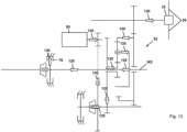
- a first brake is arranged between the first additional drive element and the power split transmission.
- the power split axle drive can therefore additionally comprise the first brake.
- the first brake can be arranged on the countershaft.
- the first brake can be at least partially connected to the countershaft, preferably connected in a rotationally fixed manner.
- the countershaft can be held or inhibited against rotation by the first brake, preferably releasably held or inhibited against rotation.
- a brake in particular the first and a second and third brake, can be understood as a frictionally engaged component which is connected on one side to a fixed element, for example a housing or a vehicle frame, and on the other side to a rotatable element, for example a shaft.
- a force is usually introduced to the connection point via an actuator, which creates a frictional force by which, for example, a rotary movement of the rotatable component is supported against the fixed component and the rotary movement is thus inhibited or prevented.
- the rotating element of the first brake can be connected to the countershaft, in particular connected in a rotationally fixed manner, and the stationary element can be connected to a transmission housing or housing or a vehicle frame.
- a non-actuated brake is understood to mean an open brake. This means that the rotatable component is in freewheel mode, i.e. that the brake preferably has no influence on the speed of the rotatable component.
- the speed of the rotatable component is reduced.
- the speed of the rotatable component can be reduced to the point of standstill. This then means that a fixed connection can be established between the rotatable component and the stationary component.
- the first brake is closed, a purely mechanical operation of the power-split axle drive can be realized, i.e. there is a rigid connection between the first and second vehicle axles, so that a rotary movement and/or a force and/or a torque can only be transmitted purely mechanically between the vehicle axles.
- the brake is open when actuated and closed when not actuated.
- a positive-locking brake is also conceivable.
- positive-locking connections two components are connected, for example in a rotationally fixed manner, due to the engagement of the contours of the components to be connected.
- Positive-locking connections have the particular advantage that they can transmit high forces and moments with comparatively small dimensions and weight.
- the energy required to create the connection is significantly lower than with frictional connections, which means that the actuator can be designed to be smaller, for example.
- the actuator for actuating the brake can be hydraulically, electromechanically, electromagnetically or, for example, pneumatically actuated.
- the actuator for actuating the brake can be designed in the same way as the actuator for actuating the switching element.
- the power-split axle drive can also comprise a fifth switching element.
- the fifth switching element can be actuated, preferably selectively actuated, particularly preferably lockable and openable and/or engageable and/or switchable and/or selectively engageable.
- the fifth switching element can be designed as a fifth clutch.
- the third gear set, in particular the fifth fixed gear, and/or the power split transmission, in particular the sun gear can be connected to the fifth or to the second shaft via the fifth shifting element, in particular connected to one another in a rotationally fixed manner.
- the fifth shifting element When the fifth shifting element is closed, the relative speed of the sun gear and the second shaft is 0 rpm. In this case, a rotary movement and/or a force and/or a torque can only be transmitted mechanically. It also offers the possibility to use the first auxiliary drive element to extract a force and/or a torque from the power-split axle drive, in particular in the above-mentioned "parking brake” and "vehicle axle brake” operating modes.
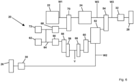
- the power-split axle drive comprises a second auxiliary drive element.
- the second auxiliary drive element can be connected to the main drive element, in particular via or with the first shaft, preferably connected in a drivable manner.
- the force and/or the rotary movement and/or the torque that can be generated by the main drive element can be introduced or transmitted to or from the second auxiliary drive element and/or the main transmission.
- the torque and/or the force and/or the rotary movement that can be generated by the main drive element can preferably be introduced and/or transmitted to the second auxiliary drive element via a transmission stage, for example a belt or chain drive or a fourth gear set or a fourth shaft.
- the second auxiliary drive element can have two directions of rotation (first direction, second direction).
- the torque and/or the force and/or the rotational movement that can be generated by the main drive element can be transmitted via the first shaft to the gear ratio and then to the second additional drive element.
- the gear ratio in particular the fourth gear set, can also comprise a fourth gear pair, in particular a sixth and a seventh fixed gear.
- the sixth fixed gear can be connected to the first shaft and the seventh fixed gear can be connected, preferably in a rotationally fixed manner, to an output shaft of the second additional drive element, for example.
- the sixth fixed gear can mesh with the seventh fixed gear, i.e. can be in constant meshing engagement with it.
- the second additional drive element is preferably an electrical machine, particularly preferably an electric motor.
- a design in the form of a hydraulic drive for example a hydrostatic drive element, is also conceivable.
- the second auxiliary drive element can be connected to the storage element and/or the first auxiliary drive element in a power electronic manner via the connecting line.
- the second auxiliary drive element can also be connected to a power electronically, in particular via the connecting line and/or a further connecting line, in a power electronic manner.
- a power electronic connection is to be understood as meaning that generated electrical energy or stored electrical energy can be fed to or taken from the storage element or fed to the consumers, for example the power take-off and/or the second auxiliary drive element.
- the power take-off like the storage element, is optionally provided. This means that a power take-off does not necessarily have to be provided. However, designs with more than one power take-off are also conceivable. Designs of power-split axle drives are also conceivable in which energy is only extracted or generated from the storage element when it is required, for example for the direct operation of the power take-off and/or the second additional drive element is required.
- the second additional drive element can be operated as a generator or as a motor.
- the second additional drive element In generator mode, the second additional drive element has a braking effect, which means that mechanical energy from a rotary movement and/or a force and/or a torque is converted into electrical energy, for example.
- energy in particular electrical energy, is fed into the second additional drive element, thereby generating a rotary movement and/or a force and/or a torque, whereby the second additional drive element has a driving or propulsive effect.
- the first and second additional drive elements can both be operated as generators at the same time, both can be operated as motors, or one can be operated as generators and one as motors.
- the second auxiliary drive element can be operated as a generator and the first auxiliary drive element as a motor.
- the second auxiliary drive element can be operated as a generator, which means that the introduced energy in the form of the rotary motion and/or the force and/or the torque is converted into electrical energy.
- This electrical energy can be used to operate the auxiliary drive, preferably the electrical auxiliary drive, and/or electrical energy can be stored in the optional storage element and/or the electrical energy can be made available to the first auxiliary drive element, with the first auxiliary drive element preferably being operated as a motor.
- the second additional drive element can also be motor-driven.
- the second additional drive element can also introduce a rotary motion and/or force and/or torque into the main transmission. This means that, for example, the drive power can be increased for a short time if this is required by the respective driving condition.
- the first additional drive element and/or the second additional drive element can also be operated as a generator, in particular in the "generator" operating mode or driving or overrun mode.
- the main drive element can be used to introduce or transmit a rotary movement and/or a force and/or a torque into the second additional drive element and via the main transmission into the power split transmission and further into the first additional drive element.
- a second shifting element and/or a second brake is or are arranged on or at the second shaft.
- the second shifting element and/or the second brake can be arranged between the power split transmission and the first vehicle axle, in particular the power split transmission and the first differential.
- the second shifting element can be arranged between the second brake and the first vehicle axle, in particular the second brake and the first differential.
- the power split transmission can be connected, preferably detachably connected, particularly preferably detachably and rotationally fixed to the first vehicle axle, in particular the first differential, via the second or with the second shifting element. and/or detachably drivable.
- the second shifting element is preferably a second clutch.
- the second shifting element can therefore be connected on one side via a part of the second shaft to the first vehicle axle, in particular the first differential, and on another side via another part of the second shaft to the power split transmission.
- the second shifting element can be actuated, preferably selectively actuated, particularly preferably lockable and openable and/or engageable and/or switchable and/or selectively engageable. With the second shifting element actuated, in particular closed, a rotary movement and/or a force and/or a torque can be transmitted from the power split transmission to the first vehicle axle, in particular via the first differential, and/or vice versa.
- the power split transmission can therefore be connected to the first vehicle axle, in particular via the first differential, with the second shifting element closed in such a way that the first vehicle axle can be driven with the power split transmission and/or vice versa.
- the second brake can be arranged in particular between the second shift element and the power split transmission.
- the second brake can be arranged on the second shaft, preferably connected to the second shaft, particularly preferably connected to the second shaft in a rotationally fixed manner.
- the second shaft can be secured against rotation by the second brake, preferably releasably secured against rotation.
- the second shaft can be releasably connected to the second brake, for example to a transmission housing or a frame, preferably releasably secured against rotation.
- the second brake can be connected to the second shaft on one side and held or inhibited against rotation on another side, for example be connected to the transmission housing or frame.
- the rotating element of the second brake can be connected to the second shaft, in particular connected in a rotationally fixed manner, and the stationary element of the second brake can be connected to a transmission housing or a frame, whereby the second shaft is held and/or inhibited in relation to a rotational movement.
- This is advantageous, for example, when a driving state is desired in which a rotational movement and/or a force and/or a torque is to be transmitted from the first additional drive element or the first vehicle axle, in particular only, to the second vehicle axle or no rotational movement and/or no force and/or no torque is to be transmitted to the first and second vehicle axles.
- the second brake and/or the second switching element further operating modes can be implemented with the power-split axle drive.
- Another operating mode can be a "fully electric” operating mode.
- the first and second switching elements as well as the second brake can be actuated in such a way that the second vehicle axle can only be driven via the first additional drive element.
- the first switching element is actuated, in particular closed, and the second switching element is actuated, in particular opened, and the second brake is actuated, in particular closed.
- This allows a power flow from the first additional drive element to the second vehicle axle to be realized, i.e. in particular a rotary movement and/or a force and/or a torque can be transmitted from the first additional drive element to the second vehicle axle.
- a rotary movement and/or a force and/or a torque, which is transmitted from the power split transmission to the second shaft, i.e. in particular in the direction of the first vehicle axle, can be held and/or inhibited and/or supported at or by the closed second brake.
- the second shaft can be held or inhibited with respect to a rotary movement using the second brake.
- the second shaft can be fixed against the gearbox housing or the frame with the second brake.
- the drive of the second vehicle axle can be provided by the first additional drive element independently of the operating state of the main drive element.
- the main drive element can be switched off or decoupled from the main transmission or the main transmission can be in neutral gear.
- the "fully electric” operating mode can be selected using the input and output unit. This advantageously enables purely electric operation of the power-split axle drive, and in particular of the vehicle. It is also advantageous that the "fully electric” operating mode can be used to implement, for example, an electrically operated crawler gear and/or maneuvering of the agricultural vehicle, in particular on a farmyard. In particular, the agricultural vehicle can advantageously be remotely controlled in the "fully electric" operating mode, for example to couple the vehicle to a work device.
- Another operating mode can be a "parking brake” operating mode.
- the second switching element and the first and second brakes can be actuated in such a way that the power-split axle drive can be implemented as a parking brake, in particular so that the vehicle is held in position.
- the second switching element is actuated, in particular closed, and the first brake is actuated, in particular closed, and the second brake is actuated, in particular closed.
- a power flow i.e. a rotary movement and/or a force and/or a torque, can be transmitted from the first and/or second vehicle axle to the power-split axle drive and supported.
- the vehicle is held in its position.
- a rotary movement and/or force and/or a torque that is transmitted from the first vehicle axle to the second shaft can be transmitted to the second brake and the second shaft can be inhibited, in particular held and/or supported, by the second brake with respect to a transmission of the rotary movement and/or the force and/or the torque.
- the second shaft can be fixed against the transmission housing or the frame with the second brake.
- a rotational movement and/or a force and/or a torque transmitted from the second vehicle axle via the first wheel set and the power split transmission and the third Wheel set on the countershaft V to the first brake and the countershaft can be inhibited, in particular held and/or supported, with the first brake with respect to a transmission of the rotary motion and/or the force and/or the torque.
- the countershaft can be fixed with the first brake against the transmission housing or the frame.
- a rotary motion and/or a force and/or a torque can also be transmitted from the second vehicle axle via the first wheel set to the power split transmission and further via the second shaft to the second brake.
- the second shaft can be inhibited, in particular held and/or supported, with the second brake with respect to a transmission of the rotary motion and/or the force and/or the torque.
- the second shaft can be fixed with the second brake against the transmission housing or the frame.
- the main drive element can be switched off or decoupled from the main transmission or the main transmission can be in neutral gear.
- the vehicle can therefore in particular be stationary.
- the "parking brake” operating mode can be selected using the input and output unit. This advantageously enables the power-split axle drive to be operated as a parking brake.
- Another operating mode can be a "vehicle axle brake” operating mode.
- the second switching element and the first and second brakes can be actuated in such a way that the power-split axle drive can be implemented as one brake, in particular the vehicle can be braked with the power-split axle drive.
- the second switching element is actuated, in particular closed, and the first and second brakes are at least partially or completely actuated, in particular at least partially or completely closed.
- the first and second brakes can therefore have a slip and/or drag.
- the speed of the countershaft can be reduced with the first brake and the speed of the second shaft can be reduced with the second brake, or even the countershaft and/or the second shaft can be held to a standstill.
- a power flow i.e. a Rotational movement and/or a force and/or a torque are transmitted from the first vehicle axle at least partially to the second brake and/or from the first vehicle axle via the power split transmission at least partially to the third shaft and further to a rear axle brake and/or from the first vehicle axle at least partially via the power split transmission to the first brake and the vehicle is braked.
- at least 10%, preferably at least 20%, particularly preferably at least 25% of the power flow of the first vehicle axle can be transmitted to the second brake.
- the main drive element can be switched on, i.e. in operation, in particular the vehicle can move.
- operation of the power split axle drive as a brake can thus be achieved.
- At least one control device is assigned to the power-split axle drive, in particular the power-split axle drive can comprise the control device.
- the control device can be connected, preferably via one or more control lines, particularly preferably via one or more bidirectional control lines, to the first and/or second auxiliary drive element and/or the power take-off and/or the storage element and/or the first and/or second and/or third and/or fourth switching element, in particular their actuators, and/or the main drive element and/or the main transmission and/or the power-split transmission and/or a first and/or second brake, in particular their actuators, for controlling and/or regulating and/or controlling them, in particular be connected to them in a signal-connected manner and/or for transmitting signals and/or for conducting data.
- control device for controlling the power-split axle drive in particular the first and/or second brake, in particular their actuators, and/or the first and/or second and/or a third and/or fourth switching element, in particular their actuators, and/or of the power split transmission and/or the first and/or second additional drive element and/or the main drive element and/or the main transmission, depending on an operating mode of the power split axle drive and/or vehicle.
- several different operating modes in particular the above-mentioned operating modes, can be provided, which can in particular be selected and specified for the at least one control device for controlling the power split axle drive.
- control device is designed such that the power split axle drive, in particular the above-mentioned components of the power split axle drive, can be controlled depending on an operating mode of the power split axle drive and/or the vehicle.
- the above-mentioned operating modes “generator” and/or “pre-run” and/or “fully electric” and/or “parking brake” and/or “vehicle axle brake” and/or both the generator and the motor operation of the first and second additional drive elements can advantageously be controlled with the control device.
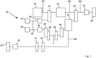
- a third shifting element is arranged between the main drive element and the second additional drive element and/or the main drive element and the main transmission, and/or a fourth shifting element is arranged between the main transmission and the main drive element and/or the main transmission and the second additional drive element.
- the third and fourth shifting elements can be arranged on or at the first shaft.
- the main drive element can be connected to the second additional drive element and/or the main transmission via the third or with the third shifting element, preferably releasably connectable, particularly preferably releasably non-rotatably and/or releasably drivable.
- the third shifting element is preferably a third clutch.
- the third shifting element can be connected to the main drive element on one side via a part of the first shaft and on another side via another part of the first shaft to the main transmission and/or, in particular via the gear ratio, in particular the fourth wheel set, to the second additional drive element.
- a selective separation or connection of the main drive element to the power-split axle drive can thus be established.
- the third switching element is open, neither a rotary movement and/or a force and/or a torque can be introduced into the power-split axle drive from the main drive element, nor vice versa from the power-split axle drive into the main drive element.
- the main drive element is thus rotationally separated from the power-split axle drive when the third switching element is open.
- the third switching element can be actuated, preferably selectively actuated, particularly preferably closable and openable and/or engageable and/or switchable and/or selectively engageable.
- a rotary movement and/or a force and/or a torque can be transmitted from the main drive element to the main transmission and/or, in particular via the gear ratio, to the second auxiliary drive element and/or vice versa.
- braking energy can be converted into electrical energy and stored in the storage element during driving and/or overrun operation when the first and/or second auxiliary drive element is operating as a generator.
- the main transmission can be connected to the second additional drive element and/or the main drive element via the fourth or with the fourth shifting element, preferably releasably connectable, particularly preferably releasably non-rotatably and/or releasably drivable.
- the fourth shifting element can preferably be a fourth clutch.
- the fourth The shifting element can therefore be connected to the main transmission on one side via a part of the first shaft and connected to the second additional drive element and/or the main drive element on another side via another part of the first shaft, in particular via the gear ratio.
- the fourth shifting element can be arranged directly adjacent to the main transmission on the first shaft.
- the fourth shifting element can be actuated, preferably selectively actuated, particularly preferably lockable and openable and/or engageable and/or switchable and/or selectively engageable. With the fourth shifting element actuated, in particular closed, a rotary movement and/or a force and/or a torque can be initiated or transmitted from the main transmission into or to the power-split axle drive and/or vice versa.
- the fourth shifting element When the fourth shifting element is open, the main transmission is decoupled from the main drive element and/or the second additional drive element. In other words, when the fourth shifting element is open, the main transmission can be rotationally separated from the main drive element and/or the second additional drive element. This means that mechanically initiated propulsion via the main transmission cannot be achieved.
- the fourth shifting element can be arranged on the side of the transmission output of the main transmission instead of between the main transmission and the main drive element or between the main transmission and the second additional drive element.
- the third shifting element When the third shifting element is open, in this case it is not the transmission input but the transmission output of the main transmission that is rotationally separated from the main drive element or the second additional drive element, which is functionally identical to the arrangement described above.
- the third and/or fourth shifting element can also be arranged in the main transmission.
- the main transmission must be in a neutral position in order to be functionally to achieve the same effect as an open fourth shift element.
- a neutral position of the main transmission means that there is no power connection between the transmission input and the transmission output of the main transmission. A rotary movement of the transmission input is therefore not transferred to the transmission output.
- the main drive element when the main drive element is switched off and the fourth shift element is open and the third shift element is closed, the main drive element can be started by motor operation of the second additional drive element.
- the invention further relates to an agricultural vehicle, in particular a tractor or tow tractor, comprising a power-split axle drive, in particular a power-split axle drive according to at least one of claims 1 to 10.
- the agricultural vehicle according to the invention has the above-described advantages of the power-split axle drive according to the invention.
- the agricultural vehicle is characterized by improved maneuverability due to smaller turning radii, which is particularly advantageous when driving in the field on the headland.
- the steering assistance also contributes to an increase in comfort. at.
- the power-split axle drive is designed to drive the vehicle, in particular to selectively drive the first and/or second vehicle axle.
- at least the second vehicle axle can be driven via the main transmission with a rotary movement and/or force and/or torque of the main drive element.
- the first vehicle axle can be a steerable front axle and/or the second vehicle axle can be a rear axle.
- control device is designed to determine different operating modes of the agricultural vehicle, in particular the power-split axle drive. It is conceivable that an operating mode can be selected by an operator of the agricultural vehicle and/or is specified to the control device. Additionally or alternatively, an operating mode can be determined depending on the operation of one of the actuators and/or components of the power-split axle drive.
- the invention further relates to a method for operating a power-split axle drive, in particular a power-split axle drive according to one of claims 1 to 10.
- the power-split axle drive can comprise a first additional drive element, a first vehicle axle, a second vehicle axle and a main drive element for providing a torque which is transmitted to a main transmission via a first shaft.
- the main transmission is connected to the second vehicle axle and at least the second vehicle axle is driven via the main transmission using the torque of the main drive element.
- the power-split axle drive further comprises a power-split transmission, wherein the power-split transmission is connected to the second vehicle axle and the main transmission via a first gear set and is connected to the first vehicle axle via a second shaft.
- the first additional drive element is connected to the power split transmission via a first switching element to introduce a torque.
- the method comprises a step of the first additional drive element acting on the power split transmission, wherein a rotary movement and/or a force and/or a torque is introduced into the power split transmission by the first additional drive element, whereby a rotary movement or an introduced torque introduced by a main transmission and/or in particular the second vehicle axle is superimposed in such a way that a lead of the second vehicle axle is changed.
- the method according to the invention has the advantages of the power split axle drive according to the invention described above.
- the method comprises a step of controlling a lead of the first vehicle axle depending on a steering angle of one of the vehicle axles, in particular the first vehicle axle or the first and second vehicle axles to each other.
- the lead can be increased or reduced as required, as described above.
- the power-split axle drive according to the invention and/or the agricultural vehicle according to the invention can also comprise the control device.
- the method according to the invention can also be carried out with the control device.
- the control device can be an electronic module and/or an embedded system and/or comprise a memory module and/or a processor.
- the control device can be connected to the first and/or second auxiliary drive element and/or the power take-off and/or the memory element and/or the first and/or second and/or third and/or fourth shift element and/or the main drive element and/or the main transmission and/or the power-split transmission and/or the first and/or second brake, preferably signal-connected and/or signal-transmitting and/or data-conducting.
- a signal-connected and/or signal-transmitting and/or data-conducting connection is to be understood as meaning that an exchange of signals takes place between the connected components.
- the signals are processed in the control device and are thus used to control and/or regulate and drive the signal-connected and/or signal-transmitting and/or data-conducting components.
- the connection can be wired, in particular with a cable, and/or wireless, i.e. wireless, for example with Bluetooth.
- the communication bus can be, for example, Isobus, CAN bus or similar.
- another control device can be controlled and/or regulated with the control device.
- the control device can be assigned to the vehicle, in particular arranged on the vehicle or assigned to the power-split axle drive or the The control device can comprise a power-split axle drive.
- the control device can also be designed in two parts, for example as part of the vehicle and as part of the power-split axle drive.
- the main drive element for providing a torque and/or the main transmission and/or the power-split transmission and/or the first and/or second additional drive element and/or the power take-off and/or the storage element and/or the first and/or second and/or third and/or fourth switching element and/or the first and/or second brake can be set and/or adjusted with the control device, and/or preferably can be controlled and/or regulated.
- the control device can be directly connected to the input and output unit arranged in a cabin of the vehicle, through which data entered by an operator can be transmitted to the control device or received and output by the latter.
- the control device is indirectly connected to the input and output unit through a higher-level control unit.
- the power-split axle drive can comprise a first actuator and/or a second actuator and/or a third actuator and/or a fourth actuator and/or a fifth actuator and/or a sixth actuator.
- the first switching element can be assigned the first actuator and/or the second switching element can be assigned the second actuator and/or the third switching element can be assigned the third actuator and/or the fourth switching element can be assigned the fourth actuator and/or the first brake can be assigned the fifth actuator and/or the second brake can be assigned the sixth actuator.
- the first and/or second and/or third and/or fourth and/or fifth and/or sixth actuators can be connected to the control device, preferably signal-connected and/or signal-transmitting and/or data-conducting.
- the first and/or second and/or third and/or fourth and/or fifth and/or sixth actuators can be actuated, in particular closed, with the control device.
- FIG. 1 shows a schematic representation of a first embodiment of an agricultural vehicle 10 according to the invention, here in particular a tractor or tractor, with a first embodiment of a power-split axle drive 20 according to the invention.
- the agricultural vehicle 10 comprises the power-split axle drive 20.
- the power-split axle drive 20 comprises a main drive element 22, a main transmission 24, a first vehicle axle 26 and a second vehicle axle 28.
- the main drive element 22 can be designed as an internal combustion engine or electric motor, in particular as an internal combustion engine.
- the first vehicle axle 26 can be a front axle and the second vehicle axle 28 a rear axle.
- the first vehicle axle 26 can be designed as a steerable axle.
- the power-split axle drive 20 can also comprise a first differential 30, in particular a front axle differential.
- the first vehicle axle 26 can be connected to the first differential 30, in particular can be connected in a drivable manner.
- the power-split axle drive 20 can also comprise a second differential 32, in particular a rear axle differential.
- the second vehicle axle 28 can be connected to the second differential 32, in particular can be connected in a drivable manner.
- a rotary motion and/or force and/or torque of the main drive element 22 can be transmitted to the first and/or second vehicle axle 26, 28 with different gear stages.
- the first and/or second vehicle axle 26, 28 convert a rotary motion and/or force and/or torque of the main drive element 22 into a rotary motion and/or force and/or torque of one or more ground engagement means 36 and thus into a propulsion of the vehicle 10.
- the vehicle 10 can have one or more ground engagement means 36, shown here in the form of wheels 38, 40, which engage with a ground 12 for transmitting drive forces and/or by means of which the vehicle 10 is supported on the ground 12.
- the vehicle 10 can also have a chassis (not shown), wherein the Chassis can be supported in particular by the wheels 38, 40 suspended on the first and/or second vehicle axle 28, 30.
- a first pair of wheels 38 are arranged on the first vehicle axle 26 and a second pair of wheels 40 on the second vehicle axle 28.
- the diameters of the wheels 38, 40 can differ from one another, in particular the diameter of the first pair of wheels 38 can be smaller than the diameter of the second pair of wheels 40.
- the ground engagement means 36 can also be designed and arranged as crawlers.
- the power-split axle drive 20 and/or the vehicle 10 can also comprise a control device 42.
- the control device 42 can be directly connected to an input and output unit 44 arranged in a cabin of the vehicle, through which data entered by an operator can be transmitted to the control device 42 or received and output by the latter.
- FIG 2 shows a schematic representation of the first embodiment of the power-split axle drive 20 according to the invention.
- the axle drive 20 shown essentially corresponds to the one in Figure 1 shown power-split axle drive 20, so that only details and/or differences are discussed below.
- the agricultural vehicle 10 can have the power-split axle drive 20, as in Figure 2 shown.
- the power-split axle drive 20 for an agricultural vehicle 10 comprises a first auxiliary drive element 50, the first vehicle axle 26, the second vehicle axle 28 and the main drive element 22 for providing a rotary movement and/or a force and/or a torque, which can be transmitted to the main transmission 24 via a first shaft W1.
- the main transmission 24 is thus connected to the main drive element 22 via or with the first shaft W1, in particular is drivably connected.
- the second vehicle axle 28 is connected to the main transmission 24, in particular is drivably connected.
- the second vehicle axle 28 is connected to the rotary movement and/or the force and/or the Torque of the main drive element 22 can be driven at least via the main transmission 24.
- the second vehicle axle 28 is connected to the main transmission 24 via or with a third shaft W3, in particular is drivably connected.
- a rotary movement and/or a force and/or a torque can be generated by the main drive element 22, which can be introduced or transmitted via the first shaft W1 into the main transmission 24 and from the main transmission 24 into or to the second vehicle axle 28.
- the power-split axle drive 20 further comprises a power-split transmission 52.
- the power-split transmission 52 is connected to the third shaft W3 via or with a first gear set 54, in particular is drivably connected.
- a first gear set 54 With the first wheel set 54, a rotary motion and/or a torque can be transmitted or introduced from the main drive element 22 to the main transmission 24 to the third shaft W3 or into the power split transmission 52.
- the first vehicle axle 26 is connected, in particular drivably connected, to the power split transmission 52 via or with a second shaft W2.
- the first additional drive element 50 can be connected to the power split transmission 52 via a first or with a first switching element 56, preferably releasably connected, particularly preferably releasably connected in a rotationally fixed manner and/or releasably drivable.
- a non-actuated first switching element 56 is understood to mean an open first switching element 56. This means that no rotational movement and/or no force and/or no torque of the first additional drive element 50 can be transmitted or introduced with or via the first switching element 56 to or into the power split transmission 52 and/or vice versa.
- first switching element 56 When the first switching element 56 is actuated, in particular closed, a rotary movement and/or a force and/or a torque of the first additional drive element 50 can be transmitted or introduced with or via the first switching element 56 to or into the power split transmission 52, and/or vice versa can be transmitted from the power split transmission 52 into the first additional drive element.
- the first Additional drive element 50 can be operated as a generator or motor.
- the power-split axle drive 20 can also include a storage element 62.
- the storage element 62 is optionally provided.
- the first additional drive element 50 can be connected to the storage element 62 in a power-electronic manner via a connecting line 64.
- One or more operating modes can be implemented with the power-split axle drive, in particular also with the vehicle.
- the main drive element 22 When the vehicle 10 and/or the power-split axle drive 20 is in driving or overrun mode, the main drive element 22 generates a rotary motion and/or a force and/or a torque, which is introduced into the main transmission 24 through the first shaft W1.
- the rotary motion and/or a force and/or a torque introduced into the main transmission 24 is translated in the main transmission 24, provided that a gear or a drive position is engaged.
- the location at which a rotary motion and/or a force and/or a torque is introduced into the main transmission 24 is shown as the transmission input, and the location at which a resulting rotary motion and/or a resulting force and/or a resulting torque is present, taking the transmission ratio into account, is referred to as the transmission output.
- the transmission input The location at which a resulting rotary motion and/or a resulting force and/or a resulting torque is present, taking the transmission ratio into account, is referred to as the transmission output.
- the transmission input and transmission output of the main transmission 24 are arranged opposite one another.
- the rotary motion and/or the force and/or the torque present at the transmission output of the main transmission 24 when the gear or drive position is engaged is introduced into the second vehicle axle 28 via the third shaft W3.
- the rotary motion and/or the force and/or the torque of the main drive element 22 is introduced or transmitted via the main transmission 24 from the second shaft W2 via the first gear set 54 into the power split transmission 52.
- the first additional drive element 50 can be operated as a generator to charge the storage element 62, in particular in driving or overrun mode.
- the generator mode of the first additional drive element 50 the rotary motion and/or force and/or torque introduced into the power split transmission 52 by the main drive element 22 is introduced or transmitted into or to the first additional drive element 50, in particular with the first switching element 56 actuated, in particular closed, and electrical energy is generated with the first additional drive element and fed to the storage element 62.
- the "advance" operating mode can also be implemented by operating the first additional drive element 50 by a motor. This allows an additional rotary movement and/or an additional force and/or an additional torque of the first additional drive element 50 to be transmitted to the power split transmission 52 via the closed first switching element 56.
- the rotary movement and/or force and/or the transmitted torque of the main drive element 22 transmitted to the power split transmission 52 and the rotary movement and/or force and/or the transmitted torque of the first additional drive element 50 transmitted to the power split transmission 52 can be superimposed on the power split transmission 52 and a resulting rotary movement and/or a resulting force and/or a resulting torque can be transmitted to the first vehicle axle 26.
- a lead of the first vehicle axle 26 can thus be adjustable, in particular controllable and/or regulated.
- the first additional drive element 50 therefore acts on the power split transmission 52 in such a way that the first additional drive element 50 introduces a rotary movement and/or a force and/or a torque into the power split transmission 52, which is superimposed on a rotary movement and/or force and/or an introduced torque introduced into the power split transmission 52 by the main drive element 22 via the main transmission in such a way that a lead of the first vehicle axle is changed.
- FIG 3 shows a schematic detailed representation of a second embodiment of the power-split axle drive 20 according to the invention.
- the axle drive 20 shown essentially corresponds to the one shown in the Figures 1 and 2 shown power-split axle drive 20, so that only details and/or differences are discussed below.
- the agricultural vehicle 10 can have the power-split axle drive 20, as in Figure 3 shown.
- the power-split axle drive 20 comprises a first differential 30, in particular a front axle differential.
- the first differential 30 is connected, in particular drivably connected, to the power-split transmission 52 via the second or with the second shaft W2.
- a rotary movement and/or a force and/or a torque of the power-split transmission 52 can be introduced or transmitted into or to the first vehicle axle 26 with or via the first differential 30.
- a rotary movement and/or a force and/or a torque of the first vehicle axle 26 can also be introduced or transmitted into or to the power-split transmission 52 with or via the first differential 30.
- the power-split axle drive 20 comprises a second differential 32, in particular a rear axle differential.
- the second differential 32 is connected, in particular drivably connected, to the main transmission 24 via the third or with the third shaft W3.
- a rotary movement and/or a force and/or a torque of the main transmission 24 can be introduced or transmitted with or via the second differential 32 into or to the second vehicle axle 28.
- the first and second differentials 30, 32 are optionally provided.
- Figure 4 shows a schematic detailed representation of a third embodiment of the power-split axle drive 20 according to the invention.
- the power-split axle drive 20 shown essentially corresponds to the one shown in the Figures 1 to 3 shown power-split axle drive 20, so that only details and/or differences are discussed below.
- the agricultural vehicle 10 can have the power-split axle drive 20, as in Figure 4 shown.
- the power-split axle drive 20 additionally comprises a countershaft V.
- the first additional drive element 50 is connectable, preferably drivable, to the countershaft V via the first or with the first shifting element 56.
- the power-split transmission 52 is also connected, in particular drivable, to the countershaft V.
- the power-split axle drive 20 comprises a second gear set 58.
- the first shifting element 56 is connected, preferably drivable, to the first additional drive element 50 via or with the second gear set 58.
- the countershaft V is connectable, preferably drivable, to the first or with the second gear set 58 via the first shifting element 56.
- the first shifting element 56 can be actuated, in particular closed, in such a way that the second gear set 58 is connected, preferably drivable, to the countershaft V via the first or with the first shifting element 56.
- the first switching element 56 can be actuated, in particular closed, in such a way that a rotary movement and/or a force and/or a torque of the first additional drive element 50 can be transmitted or introduced to or into the second gear set 58 and from the second gear set 58 to or into the first switching element 56 and from the first switching element 56 further to or into the countershaft V.
- the first switching element 56 cannot be actuated, in particular opened or closed, in such a way that no rotary movement and/or no force and/or no torque of the first additional drive element 50 can be transmitted or introduced to or into the countershaft V.
- the power-split axle drive 20 also comprises a third gear set 60.
- the power-split transmission 52 is connected, in particular drivably connected, to the countershaft V via or with the third gear set 60.
- a rotary motion and/or a force and/or a torque can be transmitted or introduced from the countershaft V to or into the power split transmission 52.
- a rotary motion and/or a force and/or a torque can be transmitted from the first additional drive element 50 via the second gear set 58 to the first shifting element 56 and from the first shifting element 56 to the countershaft V and from the countershaft V via the third or with the third gear set 60 to the Power split transmission 52 can be transmitted.
- the rotary motion and/or force and/or torque can then be transmitted, for example, from the power split transmission 52, in particular via the first differential 30, to the first vehicle axle 26.
- the "generator" operating mode i.e. in driving or overrun mode and generator operation of the first additional drive element 50
- the rotary motion and/or force and/or torque introduced into the power split transmission 52 by the main drive element 22 is introduced or transmitted from the power split transmission 52 via the third gear set 60 and the countershaft V and the first shifting element 56 and the second gear set 58 into the first additional drive element 50 and electrical energy is generated with the first additional drive element 50.
- the electrically generated energy can be fed to the storage element 62.
- an additional rotary movement and/or an additional force and/or an additional torque of the first additional drive element 50 is transmitted from the first additional drive element 50 via the second gear set 58 and the closed first shift element 56 to the countershaft V and from the countershaft V via the third gear set 60 to the power split transmission 52 and superimposed by the power split transmission 52 with the rotary movement and/or the force and/or the torque of the main drive element 22.
- the resulting rotary movement and/or force and/or the resulting torque are transmitted from the power split transmission 52 with the second shaft W2 to the first vehicle axle 26.
- the first additional drive element 50 can thus advantageously act on the power split transmission 52, whereby an advance of the first vehicle axle 26 can be regulated.
- FIG. 5 shows a schematic representation of a fourth embodiment of the power-split axle drive 20 according to the invention.
- the axle drive 20 shown essentially corresponds to the one shown in the Figures 1 to 4 shown power-split axle drive 20, so that only details and/or differences are discussed below.
- the agricultural vehicle 10 can have the power-split axle drive 20, as in Figure 5 shown.
- the power-split axle drive 20 additionally comprises a first brake 66.
- the first brake 66 is arranged between the first additional drive element 50 and the power-split transmission 52.
- the first brake 66 is connected to the countershaft V in a rotationally fixed manner.
- the countershaft V can be releasably held against rotation by the first brake 66.
- the countershaft V can be releasably connected to the first brake 66, for example to a transmission housing or a frame. This is advantageous, for example, if a driving state in all-wheel drive operation is desired in particular, in which a rigid connection between the first and second vehicle axles 26, 28 is required. In this case, the first additional drive element 50 does not have to permanently build up a counter torque and thus consume electrical energy.
- FIG 6 shows a schematic representation of a fifth embodiment of the power-split axle drive 20 according to the invention.
- the axle drive 20 shown essentially corresponds to the one shown in the Figures 1 to 5 shown power-split axle drive 20, so that only details and/or differences are discussed below.
- the agricultural vehicle 10 can have the power-split axle drive 20, as in Figure 6 shown.
- the power-split axle drive 20 comprises a second auxiliary drive element 68.
- the second auxiliary drive element 68 is connected to the main drive element 22 via or to the first shaft W1, preferably drivably connected.
- the torque and/or the force and/or the rotational movement that can be generated by the main drive element 22 can be introduced or transmitted to or from the second auxiliary drive element via a transmission stage 70, in particular a fourth gear set.
- the second auxiliary drive element 68 is connected to the storage element 62 and the first auxiliary drive element 50 in a power-electronic manner via the connecting line 64.
- the second auxiliary drive element 68 is also connected to a Power take-off 72 is connected electronically. Power take-off 72, like storage element 62, is optionally provided. This means that a power take-off 72 does not necessarily have to be provided. However, designs with more than one power take-off 72 are also conceivable.
- generated electrical energy or stored electrical energy can be fed to or taken from storage element 62 or can be fed to consumers, for example the first additional drive element 50, power take-off 72 and/or the second additional element 68 through connecting line 64.
- the rotary motion generated with main drive element 22 or the generated force and/or torque is introduced into second additional drive element 68 and/or main transmission 24, in particular with gear ratio 70, preferably the fourth gear set, and/or first shaft W1.
- the second auxiliary drive element 68 can be operated as a generator, which means that the energy introduced, in particular by the gear ratio 70, preferably the fourth gear set, and/or the first shaft W1, in the form of the rotational movement and/or the force and/or the torque is converted into electrical energy.
- This electrical energy can be used to operate the (electric) auxiliary drive 72 and/or electrical energy can be stored in the optional storage element 62 and/or the first auxiliary drive element 50 can be operated as a motor in order to increase the advance of the first vehicle axle 26. If the second auxiliary drive element 68 is operated as a generator, electrical energy is generated. This can be used to operate the auxiliary drive 72 and/or stored in the storage element 62. To charge the storage element 62, for example, the first auxiliary drive element 50 and/or the second auxiliary drive element 68 can also be operated as a generator, in particular when driving or coasting.
- the main drive element 22 can transmit a rotary movement and/or a force and/or a torque to the second auxiliary drive element 68 and via the main transmission 24 into the power split transmission 52 into the first auxiliary drive element 50. initiated or transmitted.
- the second additional drive element 68 can also initiate a rotary motion and/or force and/or torque, in particular via the transmission stage, in particular the fourth gear set, into the first shaft W1.
- the second additional drive element 68 can be operated by a motor. This means that, for example, the drive power can be increased briefly if this is required by the respective driving condition.
- FIG. 7 shows a schematic representation of a sixth embodiment of the power-split axle drive 20 according to the invention.
- the axle drive 20 shown essentially corresponds to the one shown in the Figures 1 to 6 shown power-split axle drive 20, so that only details and/or differences are discussed below.
- the agricultural vehicle 10 can have the power-split axle drive 20, as in Figure 7 shown.
- a second shifting element 74 and a second brake 76 are arranged on or at the second shaft W2.
- the second shifting element 74 and the second brake 76 are arranged between the power split transmission 52 and the first vehicle axle 26.
- the second shifting element 74 is arranged between the second brake 76 and the first vehicle axle 26.
- the power split transmission 52 can be connected, preferably detachably connected, particularly preferably detachably connected in a rotationally fixed manner and/or detachably driven, to the first vehicle axle 26, and in particular to the first differential 30, via the second or with the second shifting element 74.
- the second brake 76 is arranged between the second shifting element 74 and the power split transmission 52.
- the second brake 76 is arranged on the second shaft W2.
- the second shaft W2 can be releasably held against rotation with the second brake 76, for example with a gearbox or a frame. This allows the second shaft W2 to be held or inhibited with respect to a rotational movement.
- the second switching element 74 is designed as a second clutch.
- the second switching element 74 can be connected to the second shaft W2 on one side in a rotationally fixed manner and can be connected to another part of the second shaft W2 and thus to the power split transmission 52 on another side.
- the second brake 76 can be connected to the second shaft W2 on one side and connected to the transmission housing or frame, for example, on another side. This allows the second shaft W2 to be inhibited and/or held in relation to a rotational movement.
- Figure 8 shows a schematic representation of a seventh embodiment of the power-split axle drive 20 according to the invention.
- the axle drive 20 shown essentially corresponds to the one shown in the Figures 1 to 7 shown power-split axle drive 20, so that only details and/or differences are discussed below.
- the agricultural vehicle 10 can have the power-split axle drive 20, as in Figure 8 shown.
- a third switching element 78 is arranged between the main drive element 22 and the second additional drive element 68 and/or the main drive element 22 and the main transmission 24.
- a fourth switching element 80 is also arranged between the main transmission 24 and the main drive element 22 and/or the main transmission 24 and the second additional drive element 68.
- the main drive element 22 When the third switching element 78 is open, the main drive element 22 is decoupled from the power-split axle drive 20. This means that no rotational movement and/or force and/or torque can be introduced or transmitted from the main drive element 22 into or to the second additional drive element 68 and/or the main transmission 24. Likewise, conversely, no rotational movement and/or force and/or torque can be introduced or transmitted into or to the main drive element 22. In this case, only a purely electric driving state would be possible by the motor operation of the first additional drive element 50 and/or the second additional drive element 68 can be implemented.
- the third switching element 78 When the third switching element 78 is closed, the main drive element 22 is connected to the power-split axle drive 20.
- a rotary movement and/or a force and/or a torque can therefore be initiated or transmitted from the main drive element 22 into or to the second additional drive element 68 and/or the main transmission 24.
- a rotary movement and/or a force and/or a torque can also be initiated or transmitted into or to the main drive element 22.
- the fourth switching element 80 is open, the main transmission 24 is decoupled from the main drive element 22 and/or the second additional drive element 68. This means that mechanically initiated propulsion via the main transmission 24 cannot be represented. No rotary movement and/or force and/or torque can therefore be initiated or transmitted from the main transmission 24 into or to the power-split axle drive.
- the main drive element 22 when the main drive element 22 is switched off and the fourth switching element 80 is open and the third switching element 78 is closed, the main drive element 22 can be started by motor operation of the second additional drive element 68.
- the fourth switching element 80 When the fourth switching element 80 is closed, the main transmission 24 is connected to the main drive element 22 and/or the second additional drive element 68, in particular is drivably connected. A rotary movement and/or a force and/or a torque can therefore be introduced or transmitted from the main transmission 24 into or to the power-split axle drive.
- Figure 9 shows a schematic representation of an eighth embodiment of the power-split axle drive 20 according to the invention.
- the axle drive 20 shown essentially corresponds to the one shown in the Figures 1 to 8 shown power-split axle drive 20, so that only details and/or differences are discussed below.
- the agricultural vehicle 10 can have the power-split axle drive 20, as in Figure 9
- the power-split axle drive 20 is assigned at least one control device 42, in particular the power-split axle drive 20 can comprise the control device 42.
- the control device 42 is connected via several Control lines S, preferably via bidirectional control lines, are connected to the first and/or second auxiliary drive element 50, 68 and/or the power take-off 72 and/or the storage element 62 and/or the first and/or second and/or third and/or fourth switching element 56, 74, 78, 80 and/or the main drive element 22 and/or the main transmission 24 and/or the power split transmission 52 and/or a first and/or second brake 66, 76 for controlling and/or regulating and/or controlling them, and is in particular signal-connected and/or signal-transmitting and/or data-conductingly connected to these.
- the control device 42 is designed such that the power-split axle drive 20, in particular the above-mentioned components of the power-split axle drive 20, can be controlled depending on an operating mode of the power-split axle drive 20 and/or vehicle 10.
- the above-mentioned operating modes “generator” and/or “pre-run” and/or “fully electric” and/or “parking brake” and/or “vehicle axle brake” can be controlled with the control device 42.
- Figure 10 shows a detailed schematic representation of a ninth embodiment of the power-split axle drive 20 according to the invention, in particular the power-split transmission 52 and the first additional drive element 50.
- the power-split axle drive 20 shown essentially corresponds to the one shown in the Figures 1 to 9 shown power-split axle drive 20, so that only details and/or differences are discussed below.
- the agricultural vehicle 10 can have the power-split axle drive 20, as in Figure 10 shown.
- the first gear set 54 comprises a first gear pair, in particular a first and a second fixed gear 90, 92.
- the first fixed gear 90 is connected to the third shaft W3 and the second fixed gear 92 to the power split transmission 52, preferably connected in a rotationally fixed manner.
- the first fixed gear 90 meshes with the second fixed gear 92, and is therefore in constant meshing engagement with it.
- the second gear set 58 comprises a second gear pair, in particular a first switching gear 94 and a third fixed gear 96.
- the third fixed gear 96 is connected to the first additional drive element 50, in particular an output shaft of the first additional drive element 50, preferably drivably connected, particularly preferably connected in a rotationally fixed and/or drivable manner.
- the first switching gear 94 is rotatably mounted on the countershaft V, in particular freely rotatable and/or axially displaceable on the countershaft V.
- the first switching gear 94 is connected to one side of the first switching element 56, preferably rotationally fixed and/or drivably connected.
- the first switching gear 94 meshes with the third fixed gear 96, and is therefore in particular in constant meshing engagement with it.
- the first switching element 56 is therefore connected, preferably drivably connected, to the first additional drive element 50 via the first or with the first switching gear 94 and via the third or with the third fixed gear 96.
- the countershaft V in turn is connected to the first or via the first switching element 56 and the first switching gear 94 to the third fixed gear 96, preferably drivably connected, particularly preferably detachably drivable connected.
- the third gear set 60 comprises a third gear pair, in particular a fourth and a fifth fixed gear 98, 100.
- the fourth fixed gear 98 is connected to the countershaft V and the fifth fixed gear 100 to the power split transmission 52, in particular a sun gear 102 of the power split transmission 52, preferably connected in a rotationally fixed and/or drivable manner.
- the fourth fixed gear 98 meshes with the fifth fixed gear 100, i.e. is in particular in constant meshing engagement with it.
- the power split transmission 52 is designed as a planetary transmission.
- a ring gear 104 of the power split transmission 52 is connected to the third shaft W3 via or with the first gear set 54, in particular is drivably connected.
- the ring gear 104 is connected to the second fixed gear 92, preferably in a rotationally fixed and/or drivable manner.
- the first vehicle axle 26 is connected to the third shaft W3 via or with the second shaft W2 is connected, in particular drivably connected, to a planet carrier 106 or a web of the power split transmission 52.
- the planet carrier 106 is connected to the second shaft W2, preferably connected in a rotationally fixed and/or drivable manner.
- a planetary gear set in particular one or more planetary wheels 108, is rotatably mounted on the planet carrier 106, each of which meshes with the sun gear 102 and the ring gear 104, i.e. is in constant meshing engagement with them.
- the planetary gear set can in particular have a set of planetary gears 108.
- the planetary gear set can comprise three planetary gears 108.
- the sun gear 102 of the power split transmission 52 is connected, in particular drivably connected, to the first additional drive element via the fifth fixed gear 100 and the fourth fixed gear 98, and in particular further via the countershaft V and the shifting element and the second gear set.
- a force and/or a torque can be transmitted from the first additional drive element via the second gear set and the shifting element to the countershaft and from the countershaft via the fourth fixed gear 98 and the fifth fixed gear 100 to the sun gear 102 of the power split transmission 52.
- Figure 11 shows a detailed schematic representation of a tenth embodiment of the power-split axle drive 20 according to the invention, in particular the power-split transmission 52 and the first additional drive element 50.
- the power-split axle drive 20 shown essentially corresponds to the one shown in the Figures 1 to 10 shown power-split axle drive 20, so that only details and/or differences are discussed below.
- the agricultural vehicle 10 can have the power-split axle drive 20, as in Figure 11 shown.
- the first brake 66 is arranged on the countershaft V.
- the first brake 66 is connected to the countershaft V, preferably drivable with the countershaft V connected, particularly preferably connected to the countershaft V in a rotationally fixed and/or drivable manner.
- the power split transmission 52 When the first brake 66 is actuated, i.e. in particular closed, the power split transmission 52 operates with a fixed ratio, i.e. completely mechanically. The power split transmission 52 can then transfer the braking torque from the first vehicle axle 26 to the vehicle brake or rear axle brake (on the second vehicle axle 28). Likewise, more mechanical power can be transferred to the first vehicle axle 26 with the first brake 66.
- Figure 12 shows a detailed schematic representation of an eleventh embodiment of the power-split axle drive 20 according to the invention.
- the axle drive 20 shown essentially corresponds to the one shown in the Figures 1 to 11 shown power-split axle drive 20, so that only details and/or differences are discussed below.
- the agricultural vehicle 10 can have the power-split axle drive 20, as in Figure 12
- the second switching element 74 and the second brake 76 are arranged on the second shaft W2 between the power split transmission 52 and the first vehicle axle 26.
- the Figures 13 to 15 show schematic representations of the power flow in the "fully electric” operating mode, "parking brake” operating mode and “vehicle axle brake” operating mode in the power-split axle drive 20 according to the invention.
- the Figure 13 to 15 The power-split axle drive 20 shown essentially corresponds to the one shown in the Figures 1 to 12 shown power-split axle drive 20, so that only details and/or differences are discussed below.
- the arrows 120 show the direction of the power flow, i.e. the direction of the transmission of a rotary motion and/or a force and/or a torque.
- the size of the arrows 120 schematically shows the size of the transmitted rotary motion and/or force and/or the transmitted torque.
- Figure 13 shows the power flow of the "fully electric” operating mode.
- a power flow i.e. a rotary movement and/or a force and/or a torque
- a rotary movement and/or a force and/or a torque which is transmitted from the power split transmission 52 to the second shaft W2, i.e. in particular in the direction of the first vehicle axle 26, can be held and/or inhibited and/or supported at or by the closed second brake 76.
- the second shaft W2 can be held or inhibited with the second brake 76 with respect to a rotary movement of the second shaft W2.
- Figure 14 shows the power flow of the "parking brake” operating mode.
- a power flow i.e. a rotary movement and/or a force and/or a torque
- a power flow is transmitted from the first and/or second vehicle axle 26, 28 to the power-split axle drive 20 and supported. This holds the vehicle in its position.
- Figure 15 shows the power flow of the "vehicle axle brake” operating mode.
- a power flow i.e. a rotary movement and/or a force and/or a torque
- the power-split axle drive 20 is transmitted from the first and/or second vehicle axle 26, 28 to the power-split axle drive 20 and at least partially inhibited and/or held and at least partially transmitted to the rear axle brake. This brakes the vehicle, particularly when driving or coasting.
- Figure 16 shows a detailed schematic representation of a twelfth embodiment of the power-split axle drive 20 according to the invention.
- the axle drive 20 shown essentially corresponds to the one shown in the Figures 1 to 15 shown power-split axle drive 20, so that only details and/or differences are discussed below.
- the agricultural vehicle 10 can have the power-split axle drive 20, as in Figure 16 shown, include.
- the power split transmission 52 alternatively comprises a fifth switching element 130 instead of the first brake 66.
- the fifth switching element 130 is designed as a fifth clutch.
- the fifth fixed gear 100 and/or the sun gear 102 are connected to the second shaft W2 in a rotationally fixed manner via the closed fifth switching element 130.
- the first and second vehicle axles 26, 28 are thus both mechanically driven by the main drive element 22.
- the relative speed of the sun gear 102 and the second shaft W2 is 0 (zero) revolutions per minute. This means that the ring gear 104 rotates at the same speed as the sun gear 102 and the second shaft W2.
- a rotational speed and/or a force and/or a torque of the first additional drive element 50 can be transmitted or introduced into the power split transmission 52 by the fifth fixed gear 100 and/or the sun gear 102.
Landscapes
- Engineering & Computer Science (AREA)
- Chemical & Material Sciences (AREA)
- Combustion & Propulsion (AREA)
- Transportation (AREA)
- Mechanical Engineering (AREA)
- Arrangement And Driving Of Transmission Devices (AREA)
- Retarders (AREA)
Priority Applications (2)
| Application Number | Priority Date | Filing Date | Title |
|---|---|---|---|
| EP24180479.8A EP4417451B1 (fr) | 2022-01-19 | 2022-01-19 | Entraînement d'essieu à répartition de puissance et véhicule agricole |
| EP25219249.7A EP4707021A3 (fr) | 2022-01-19 | 2022-01-19 | Entraînement d'essieu à répartition de puissance, véhicule agricole et procédé de fonctionnement d'un entraînement d'essieu à répartition de puissance |
Applications Claiming Priority (2)
| Application Number | Priority Date | Filing Date | Title |
|---|---|---|---|
| EP22152192.5A EP4215392B1 (fr) | 2022-01-19 | 2022-01-19 | Entraînement d'essieu à répartition de puissance et véhicule agricole |
| EP24180479.8A EP4417451B1 (fr) | 2022-01-19 | 2022-01-19 | Entraînement d'essieu à répartition de puissance et véhicule agricole |
Related Parent Applications (2)
| Application Number | Title | Priority Date | Filing Date |
|---|---|---|---|
| EP22152192.5A Division EP4215392B1 (fr) | 2022-01-19 | 2022-01-19 | Entraînement d'essieu à répartition de puissance et véhicule agricole |
| EP22152192.5A Division-Into EP4215392B1 (fr) | 2022-01-19 | 2022-01-19 | Entraînement d'essieu à répartition de puissance et véhicule agricole |
Related Child Applications (1)
| Application Number | Title | Priority Date | Filing Date |
|---|---|---|---|
| EP25219249.7A Division EP4707021A3 (fr) | 2022-01-19 | 2022-01-19 | Entraînement d'essieu à répartition de puissance, véhicule agricole et procédé de fonctionnement d'un entraînement d'essieu à répartition de puissance |
Publications (3)
| Publication Number | Publication Date |
|---|---|
| EP4417451A2 true EP4417451A2 (fr) | 2024-08-21 |
| EP4417451A3 EP4417451A3 (fr) | 2024-10-23 |
| EP4417451B1 EP4417451B1 (fr) | 2025-12-24 |
Family
ID=79730499
Family Applications (3)
| Application Number | Title | Priority Date | Filing Date |
|---|---|---|---|
| EP25219249.7A Pending EP4707021A3 (fr) | 2022-01-19 | 2022-01-19 | Entraînement d'essieu à répartition de puissance, véhicule agricole et procédé de fonctionnement d'un entraînement d'essieu à répartition de puissance |
| EP24180479.8A Active EP4417451B1 (fr) | 2022-01-19 | 2022-01-19 | Entraînement d'essieu à répartition de puissance et véhicule agricole |
| EP22152192.5A Active EP4215392B1 (fr) | 2022-01-19 | 2022-01-19 | Entraînement d'essieu à répartition de puissance et véhicule agricole |
Family Applications Before (1)
| Application Number | Title | Priority Date | Filing Date |
|---|---|---|---|
| EP25219249.7A Pending EP4707021A3 (fr) | 2022-01-19 | 2022-01-19 | Entraînement d'essieu à répartition de puissance, véhicule agricole et procédé de fonctionnement d'un entraînement d'essieu à répartition de puissance |
Family Applications After (1)
| Application Number | Title | Priority Date | Filing Date |
|---|---|---|---|
| EP22152192.5A Active EP4215392B1 (fr) | 2022-01-19 | 2022-01-19 | Entraînement d'essieu à répartition de puissance et véhicule agricole |
Country Status (1)
| Country | Link |
|---|---|
| EP (3) | EP4707021A3 (fr) |
Families Citing this family (1)
| Publication number | Priority date | Publication date | Assignee | Title |
|---|---|---|---|---|
| DE102024102491A1 (de) | 2024-01-29 | 2025-07-31 | Deere & Company | Leistungsverzweigter Achsantrieb, landwirtschaftliches Zugfahrzeug und Verfahren zum Betreiben eines leistungsverzweigten Achsantriebs |
Citations (3)
| Publication number | Priority date | Publication date | Assignee | Title |
|---|---|---|---|---|
| DE102007021732A1 (de) | 2007-05-09 | 2008-11-20 | Agco Gmbh | Antriebssystem für Fahrzeuge mit mindestens zwei antreibbaren Fahrzeugachsen |
| DE102013224383A1 (de) | 2013-11-28 | 2015-05-28 | Zf Friedrichshafen Ag | Leistungsverzweigter Achsantrieb für Arbeitsmaschinen |
| EP3626502A1 (fr) | 2018-09-18 | 2020-03-25 | CLAAS Tractor S.A.S. | Chaîne cinématique pour un véhicule agricole |
Family Cites Families (5)
| Publication number | Priority date | Publication date | Assignee | Title |
|---|---|---|---|---|
| JP2007045177A (ja) * | 2005-08-05 | 2007-02-22 | Yanmar Co Ltd | 前輪増速制御装置 |
| US8888638B2 (en) * | 2009-06-05 | 2014-11-18 | Magna Powertrain Of America, Inc. | Multi-mode hybrid electric transfer case for four-wheel drive vehicle |
| DE102014009866B4 (de) * | 2014-07-03 | 2017-03-16 | Daimler Ag | Antriebsstrangvorrichtung für ein Kraftfahrzeug |
| DE102017215012A1 (de) * | 2016-09-15 | 2018-03-15 | Deere & Company | Antriebssystem und Verfahren |
| DE102017218858B4 (de) * | 2017-04-06 | 2019-02-21 | Magna powertrain gmbh & co kg | Fahrzeug mit Verteilergetriebe und Verfahren zum Betrieb dieses Fahrzeugs |
-
2022
- 2022-01-19 EP EP25219249.7A patent/EP4707021A3/fr active Pending
- 2022-01-19 EP EP24180479.8A patent/EP4417451B1/fr active Active
- 2022-01-19 EP EP22152192.5A patent/EP4215392B1/fr active Active
Patent Citations (3)
| Publication number | Priority date | Publication date | Assignee | Title |
|---|---|---|---|---|
| DE102007021732A1 (de) | 2007-05-09 | 2008-11-20 | Agco Gmbh | Antriebssystem für Fahrzeuge mit mindestens zwei antreibbaren Fahrzeugachsen |
| DE102013224383A1 (de) | 2013-11-28 | 2015-05-28 | Zf Friedrichshafen Ag | Leistungsverzweigter Achsantrieb für Arbeitsmaschinen |
| EP3626502A1 (fr) | 2018-09-18 | 2020-03-25 | CLAAS Tractor S.A.S. | Chaîne cinématique pour un véhicule agricole |
Also Published As
| Publication number | Publication date |
|---|---|
| EP4417451B1 (fr) | 2025-12-24 |
| EP4417451A3 (fr) | 2024-10-23 |
| EP4215392A1 (fr) | 2023-07-26 |
| EP4707021A3 (fr) | 2026-04-22 |
| EP4707021A2 (fr) | 2026-03-11 |
| EP4215392B1 (fr) | 2024-09-25 |
Similar Documents
| Publication | Publication Date | Title |
|---|---|---|
| DE102013224383A1 (de) | Leistungsverzweigter Achsantrieb für Arbeitsmaschinen | |
| EP1876080B1 (fr) | Système d'entraînement pour un chariot de manutention doté d'un moteur à combustion interne | |
| EP2289751B1 (fr) | Chaîne de transmission hybride pour un véhicule automobile et son procédé de fonctionnement | |
| DE102018203670A1 (de) | Stufenloses Getriebe mit Power Reverser | |
| DE102013206176A1 (de) | Fahrzeugantrieb | |
| WO2016062384A1 (fr) | Dispositif d'entraînement pour un véhicule à moteur, véhicule à moteur et procédé permettant de faire fonctionner un véhicule à moteur | |
| EP1747110A2 (fr) | Ensemble moteur pour vehicules automobiles | |
| DE102012021292A1 (de) | Antriebsvorrichtung für ein Geschwindigkeits-Wechselgetriebe | |
| EP3406474B1 (fr) | Dispositif d'entraînement hybride électro-hydraulique pour un véhicule automobile | |
| DE102010053447A1 (de) | Antriebseinheit, insbesondere Heckantriebseinheit, für einen Allradantrieb eines Kraftfahrzeuges | |
| EP3626502B1 (fr) | Chaîne cinématique pour un véhicule agricole | |
| EP2562442B1 (fr) | Boîte de vitesse, en particulier pour une chaîne de transmission dans des véhicules automobiles, des véhicules sur rail ou analogues | |
| EP4215393B1 (fr) | Entraînement d'essieu à répartition de puissance et véhicule agricole | |
| DE102021209593A1 (de) | Antriebseinheit für ein Elektrofahrzeug | |
| DE102023110038B4 (de) | Mehrachsantriebseinheit für ein Kraftfahrzeug, Kraftfahrzeug und Verfahren zum Betreiben des Kraftfahrzeugs | |
| EP4215392B1 (fr) | Entraînement d'essieu à répartition de puissance et véhicule agricole | |
| DE102020214519B4 (de) | Hybrid-Getriebe für einen Kraftfahrzeugantriebsstrang | |
| DE102022204741B4 (de) | Antriebsvorrichtung für eine Arbeitsmaschine | |
| DE102022101166A1 (de) | Leistungsverzweigter Achsantrieb und landwirtschaftliches Fahrzeug | |
| DE102021205940B4 (de) | Getriebe und Antriebsstrang für ein Kraftfahrzeug | |
| EP4592119A1 (fr) | Entraînement d'essieu à répartition de puissance, véhicule tracteur agricole et procédé de fonctionnement d'un entraînement d'essieu à répartition de puissance | |
| EP4722566A2 (fr) | Stratégie de changement de vitesse pour une transmission | |
| DE102021124260B4 (de) | Steuervorrichtung und Verfahren zum Steuern eines Fahrzeugantriebsstranges mit Nebenabtrieb | |
| DE102024210225A1 (de) | Antriebsstrang einer Arbeitsmaschine | |
| DE102018133109B4 (de) | Antriebsstrang für ein Kraftfahrzeug und Verfahren zum Betrieb eines Antriebsstrangs sowie Kraftfahrzeug |
Legal Events
| Date | Code | Title | Description |
|---|---|---|---|
| PUAI | Public reference made under article 153(3) epc to a published international application that has entered the european phase |
Free format text: ORIGINAL CODE: 0009012 |
|
| STAA | Information on the status of an ep patent application or granted ep patent |
Free format text: STATUS: THE APPLICATION HAS BEEN PUBLISHED |
|
| AC | Divisional application: reference to earlier application |
Ref document number: 4215392 Country of ref document: EP Kind code of ref document: P |
|
| AK | Designated contracting states |
Kind code of ref document: A2 Designated state(s): AL AT BE BG CH CY CZ DE DK EE ES FI FR GB GR HR HU IE IS IT LI LT LU LV MC MK MT NL NO PL PT RO RS SE SI SK SM TR |
|
| REG | Reference to a national code |
Ref country code: DE Free format text: PREVIOUS MAIN CLASS: B60K0006365000 Ref country code: DE Ref legal event code: R079 Ref document number: 502022006580 Country of ref document: DE Free format text: PREVIOUS MAIN CLASS: B60K0006365000 Ipc: B60K0006520000 |
|
| PUAL | Search report despatched |
Free format text: ORIGINAL CODE: 0009013 |
|
| AK | Designated contracting states |
Kind code of ref document: A3 Designated state(s): AL AT BE BG CH CY CZ DE DK EE ES FI FR GB GR HR HU IE IS IT LI LT LU LV MC MK MT NL NO PL PT RO RS SE SI SK SM TR |
|
| RIC1 | Information provided on ipc code assigned before grant |
Ipc: B60K 6/442 20071001ALN20240918BHEP Ipc: B60K 23/08 20060101ALI20240918BHEP Ipc: B60K 6/365 20071001ALI20240918BHEP Ipc: B60K 6/387 20071001ALI20240918BHEP Ipc: B60K 17/344 20060101ALI20240918BHEP Ipc: B60K 6/48 20071001ALI20240918BHEP Ipc: B60K 6/52 20071001AFI20240918BHEP |
|
| STAA | Information on the status of an ep patent application or granted ep patent |
Free format text: STATUS: REQUEST FOR EXAMINATION WAS MADE |
|
| 17P | Request for examination filed |
Effective date: 20250423 |
|
| GRAP | Despatch of communication of intention to grant a patent |
Free format text: ORIGINAL CODE: EPIDOSNIGR1 |
|
| STAA | Information on the status of an ep patent application or granted ep patent |
Free format text: STATUS: GRANT OF PATENT IS INTENDED |
|
| RIC1 | Information provided on ipc code assigned before grant |
Ipc: B60K 6/52 20071001AFI20250819BHEP Ipc: B60K 6/48 20071001ALI20250819BHEP Ipc: B60K 17/344 20060101ALI20250819BHEP Ipc: B60K 6/387 20071001ALI20250819BHEP Ipc: B60K 6/365 20071001ALI20250819BHEP Ipc: B60K 23/08 20060101ALI20250819BHEP Ipc: B60K 6/442 20071001ALN20250819BHEP |
|
| INTG | Intention to grant announced |
Effective date: 20250909 |
|
| RIC1 | Information provided on ipc code assigned before grant |
Ipc: B60K 6/52 20071001AFI20250829BHEP Ipc: B60K 6/48 20071001ALI20250829BHEP Ipc: B60K 17/344 20060101ALI20250829BHEP Ipc: B60K 6/387 20071001ALI20250829BHEP Ipc: B60K 6/365 20071001ALI20250829BHEP Ipc: B60K 23/08 20060101ALI20250829BHEP Ipc: B60K 6/442 20071001ALN20250829BHEP |
|
| GRAS | Grant fee paid |
Free format text: ORIGINAL CODE: EPIDOSNIGR3 |
|
| GRAA | (expected) grant |
Free format text: ORIGINAL CODE: 0009210 |
|
| STAA | Information on the status of an ep patent application or granted ep patent |
Free format text: STATUS: THE PATENT HAS BEEN GRANTED |
|
| AC | Divisional application: reference to earlier application |
Ref document number: 4215392 Country of ref document: EP Kind code of ref document: P |
|
| AK | Designated contracting states |
Kind code of ref document: B1 Designated state(s): AL AT BE BG CH CY CZ DE DK EE ES FI FR GB GR HR HU IE IS IT LI LT LU LV MC MK MT NL NO PL PT RO RS SE SI SK SM TR |
|
| REG | Reference to a national code |
Ref country code: CH Ref legal event code: F10 Free format text: ST27 STATUS EVENT CODE: U-0-0-F10-F00 (AS PROVIDED BY THE NATIONAL OFFICE) Effective date: 20251224 Ref country code: GB Ref legal event code: FG4D Free format text: NOT ENGLISH |
|
| REG | Reference to a national code |
Ref country code: DE Ref legal event code: R096 Ref document number: 502022006580 Country of ref document: DE |
|
| REG | Reference to a national code |
Ref country code: LT Ref legal event code: MG9D |
|
| PG25 | Lapsed in a contracting state [announced via postgrant information from national office to epo] |
Ref country code: NO Free format text: LAPSE BECAUSE OF FAILURE TO SUBMIT A TRANSLATION OF THE DESCRIPTION OR TO PAY THE FEE WITHIN THE PRESCRIBED TIME-LIMIT Effective date: 20260324 |
|
| PGFP | Annual fee paid to national office [announced via postgrant information from national office to epo] |
Ref country code: DE Payment date: 20260128 Year of fee payment: 5 |
|
| PG25 | Lapsed in a contracting state [announced via postgrant information from national office to epo] |
Ref country code: FI Free format text: LAPSE BECAUSE OF FAILURE TO SUBMIT A TRANSLATION OF THE DESCRIPTION OR TO PAY THE FEE WITHIN THE PRESCRIBED TIME-LIMIT Effective date: 20251224 Ref country code: HR Free format text: LAPSE BECAUSE OF FAILURE TO SUBMIT A TRANSLATION OF THE DESCRIPTION OR TO PAY THE FEE WITHIN THE PRESCRIBED TIME-LIMIT Effective date: 20251224 |
|
| PGFP | Annual fee paid to national office [announced via postgrant information from national office to epo] |
Ref country code: AT Payment date: 20260301 Year of fee payment: 5 |
|
| PG25 | Lapsed in a contracting state [announced via postgrant information from national office to epo] |
Ref country code: RS Free format text: LAPSE BECAUSE OF FAILURE TO SUBMIT A TRANSLATION OF THE DESCRIPTION OR TO PAY THE FEE WITHIN THE PRESCRIBED TIME-LIMIT Effective date: 20260324 |
|
| PGFP | Annual fee paid to national office [announced via postgrant information from national office to epo] |
Ref country code: FR Payment date: 20260126 Year of fee payment: 5 |
|
| PG25 | Lapsed in a contracting state [announced via postgrant information from national office to epo] |
Ref country code: LV Free format text: LAPSE BECAUSE OF FAILURE TO SUBMIT A TRANSLATION OF THE DESCRIPTION OR TO PAY THE FEE WITHIN THE PRESCRIBED TIME-LIMIT Effective date: 20251224 |