EP4417533A2 - Palette de transport à voies multiples - Google Patents
Palette de transport à voies multiples Download PDFInfo
- Publication number
- EP4417533A2 EP4417533A2 EP24158196.6A EP24158196A EP4417533A2 EP 4417533 A2 EP4417533 A2 EP 4417533A2 EP 24158196 A EP24158196 A EP 24158196A EP 4417533 A2 EP4417533 A2 EP 4417533A2
- Authority
- EP
- European Patent Office
- Prior art keywords
- pallet
- deck
- reusable transport
- feet
- transport pallet
- Prior art date
- Legal status (The legal status is an assumption and is not a legal conclusion. Google has not performed a legal analysis and makes no representation as to the accuracy of the status listed.)
- Withdrawn
Links
Images


Classifications
-
- B—PERFORMING OPERATIONS; TRANSPORTING
- B65—CONVEYING; PACKING; STORING; HANDLING THIN OR FILAMENTARY MATERIAL
- B65D—CONTAINERS FOR STORAGE OR TRANSPORT OF ARTICLES OR MATERIALS, e.g. BAGS, BARRELS, BOTTLES, BOXES, CANS, CARTONS, CRATES, DRUMS, JARS, TANKS, HOPPERS, FORWARDING CONTAINERS; ACCESSORIES, CLOSURES, OR FITTINGS THEREFOR; PACKAGING ELEMENTS; PACKAGES
- B65D19/00—Pallets or like platforms, with or without side walls, for supporting loads to be lifted or lowered
- B65D19/0004—Rigid pallets without side walls
- B65D19/0006—Rigid pallets without side walls the load supporting surface being made of a single element
- B65D19/003—Rigid pallets without side walls the load supporting surface being made of a single element forming discontinuous or non-planar contact surfaces
- B65D19/0032—Rigid pallets without side walls the load supporting surface being made of a single element forming discontinuous or non-planar contact surfaces the base surface being made of a single element
- B65D19/0036—Rigid pallets without side walls the load supporting surface being made of a single element forming discontinuous or non-planar contact surfaces the base surface being made of a single element forming discontinuous or non-planar contact surfaces
- B65D19/004—Rigid pallets without side walls the load supporting surface being made of a single element forming discontinuous or non-planar contact surfaces the base surface being made of a single element forming discontinuous or non-planar contact surfaces and each contact surface having a discrete foot-like shape
-
- B—PERFORMING OPERATIONS; TRANSPORTING
- B65—CONVEYING; PACKING; STORING; HANDLING THIN OR FILAMENTARY MATERIAL
- B65D—CONTAINERS FOR STORAGE OR TRANSPORT OF ARTICLES OR MATERIALS, e.g. BAGS, BARRELS, BOTTLES, BOXES, CANS, CARTONS, CRATES, DRUMS, JARS, TANKS, HOPPERS, FORWARDING CONTAINERS; ACCESSORIES, CLOSURES, OR FITTINGS THEREFOR; PACKAGING ELEMENTS; PACKAGES
- B65D2203/00—Decoration means, markings, information elements, contents indicators
- B65D2203/10—Transponders
-
- B—PERFORMING OPERATIONS; TRANSPORTING
- B65—CONVEYING; PACKING; STORING; HANDLING THIN OR FILAMENTARY MATERIAL
- B65D—CONTAINERS FOR STORAGE OR TRANSPORT OF ARTICLES OR MATERIALS, e.g. BAGS, BARRELS, BOTTLES, BOXES, CANS, CARTONS, CRATES, DRUMS, JARS, TANKS, HOPPERS, FORWARDING CONTAINERS; ACCESSORIES, CLOSURES, OR FITTINGS THEREFOR; PACKAGING ELEMENTS; PACKAGES
- B65D2519/00—Pallets or like platforms, with or without side walls, for supporting loads to be lifted or lowered
- B65D2519/00004—Details relating to pallets
- B65D2519/00009—Materials
- B65D2519/00014—Materials for the load supporting surface
- B65D2519/00034—Plastic
-
- B—PERFORMING OPERATIONS; TRANSPORTING
- B65—CONVEYING; PACKING; STORING; HANDLING THIN OR FILAMENTARY MATERIAL
- B65D—CONTAINERS FOR STORAGE OR TRANSPORT OF ARTICLES OR MATERIALS, e.g. BAGS, BARRELS, BOTTLES, BOXES, CANS, CARTONS, CRATES, DRUMS, JARS, TANKS, HOPPERS, FORWARDING CONTAINERS; ACCESSORIES, CLOSURES, OR FITTINGS THEREFOR; PACKAGING ELEMENTS; PACKAGES
- B65D2519/00—Pallets or like platforms, with or without side walls, for supporting loads to be lifted or lowered
- B65D2519/00004—Details relating to pallets
- B65D2519/00009—Materials
- B65D2519/00049—Materials for the base surface
- B65D2519/00069—Plastic
-
- B—PERFORMING OPERATIONS; TRANSPORTING
- B65—CONVEYING; PACKING; STORING; HANDLING THIN OR FILAMENTARY MATERIAL
- B65D—CONTAINERS FOR STORAGE OR TRANSPORT OF ARTICLES OR MATERIALS, e.g. BAGS, BARRELS, BOTTLES, BOXES, CANS, CARTONS, CRATES, DRUMS, JARS, TANKS, HOPPERS, FORWARDING CONTAINERS; ACCESSORIES, CLOSURES, OR FITTINGS THEREFOR; PACKAGING ELEMENTS; PACKAGES
- B65D2519/00—Pallets or like platforms, with or without side walls, for supporting loads to be lifted or lowered
- B65D2519/00004—Details relating to pallets
- B65D2519/00009—Materials
- B65D2519/00119—Materials for the construction of the reinforcements
- B65D2519/00129—Metal
-
- B—PERFORMING OPERATIONS; TRANSPORTING
- B65—CONVEYING; PACKING; STORING; HANDLING THIN OR FILAMENTARY MATERIAL
- B65D—CONTAINERS FOR STORAGE OR TRANSPORT OF ARTICLES OR MATERIALS, e.g. BAGS, BARRELS, BOTTLES, BOXES, CANS, CARTONS, CRATES, DRUMS, JARS, TANKS, HOPPERS, FORWARDING CONTAINERS; ACCESSORIES, CLOSURES, OR FITTINGS THEREFOR; PACKAGING ELEMENTS; PACKAGES
- B65D2519/00—Pallets or like platforms, with or without side walls, for supporting loads to be lifted or lowered
- B65D2519/00004—Details relating to pallets
- B65D2519/00258—Overall construction
- B65D2519/00263—Overall construction of the pallet
- B65D2519/00268—Overall construction of the pallet made of one piece
-
- B—PERFORMING OPERATIONS; TRANSPORTING
- B65—CONVEYING; PACKING; STORING; HANDLING THIN OR FILAMENTARY MATERIAL
- B65D—CONTAINERS FOR STORAGE OR TRANSPORT OF ARTICLES OR MATERIALS, e.g. BAGS, BARRELS, BOTTLES, BOXES, CANS, CARTONS, CRATES, DRUMS, JARS, TANKS, HOPPERS, FORWARDING CONTAINERS; ACCESSORIES, CLOSURES, OR FITTINGS THEREFOR; PACKAGING ELEMENTS; PACKAGES
- B65D2519/00—Pallets or like platforms, with or without side walls, for supporting loads to be lifted or lowered
- B65D2519/00004—Details relating to pallets
- B65D2519/00258—Overall construction
- B65D2519/00283—Overall construction of the load supporting surface
- B65D2519/00288—Overall construction of the load supporting surface made of one piece
-
- B—PERFORMING OPERATIONS; TRANSPORTING
- B65—CONVEYING; PACKING; STORING; HANDLING THIN OR FILAMENTARY MATERIAL
- B65D—CONTAINERS FOR STORAGE OR TRANSPORT OF ARTICLES OR MATERIALS, e.g. BAGS, BARRELS, BOTTLES, BOXES, CANS, CARTONS, CRATES, DRUMS, JARS, TANKS, HOPPERS, FORWARDING CONTAINERS; ACCESSORIES, CLOSURES, OR FITTINGS THEREFOR; PACKAGING ELEMENTS; PACKAGES
- B65D2519/00—Pallets or like platforms, with or without side walls, for supporting loads to be lifted or lowered
- B65D2519/00004—Details relating to pallets
- B65D2519/00258—Overall construction
- B65D2519/00283—Overall construction of the load supporting surface
- B65D2519/00308—Overall construction of the load supporting surface grid type, e.g. perforated plate
-
- B—PERFORMING OPERATIONS; TRANSPORTING
- B65—CONVEYING; PACKING; STORING; HANDLING THIN OR FILAMENTARY MATERIAL
- B65D—CONTAINERS FOR STORAGE OR TRANSPORT OF ARTICLES OR MATERIALS, e.g. BAGS, BARRELS, BOTTLES, BOXES, CANS, CARTONS, CRATES, DRUMS, JARS, TANKS, HOPPERS, FORWARDING CONTAINERS; ACCESSORIES, CLOSURES, OR FITTINGS THEREFOR; PACKAGING ELEMENTS; PACKAGES
- B65D2519/00—Pallets or like platforms, with or without side walls, for supporting loads to be lifted or lowered
- B65D2519/00004—Details relating to pallets
- B65D2519/00258—Overall construction
- B65D2519/00313—Overall construction of the base surface
- B65D2519/00318—Overall construction of the base surface made of one piece
-
- B—PERFORMING OPERATIONS; TRANSPORTING
- B65—CONVEYING; PACKING; STORING; HANDLING THIN OR FILAMENTARY MATERIAL
- B65D—CONTAINERS FOR STORAGE OR TRANSPORT OF ARTICLES OR MATERIALS, e.g. BAGS, BARRELS, BOTTLES, BOXES, CANS, CARTONS, CRATES, DRUMS, JARS, TANKS, HOPPERS, FORWARDING CONTAINERS; ACCESSORIES, CLOSURES, OR FITTINGS THEREFOR; PACKAGING ELEMENTS; PACKAGES
- B65D2519/00—Pallets or like platforms, with or without side walls, for supporting loads to be lifted or lowered
- B65D2519/00004—Details relating to pallets
- B65D2519/00258—Overall construction
- B65D2519/00313—Overall construction of the base surface
- B65D2519/00328—Overall construction of the base surface shape of the contact surface of the base
- B65D2519/00338—Overall construction of the base surface shape of the contact surface of the base contact surface having a discrete foot-like shape
-
- B—PERFORMING OPERATIONS; TRANSPORTING
- B65—CONVEYING; PACKING; STORING; HANDLING THIN OR FILAMENTARY MATERIAL
- B65D—CONTAINERS FOR STORAGE OR TRANSPORT OF ARTICLES OR MATERIALS, e.g. BAGS, BARRELS, BOTTLES, BOXES, CANS, CARTONS, CRATES, DRUMS, JARS, TANKS, HOPPERS, FORWARDING CONTAINERS; ACCESSORIES, CLOSURES, OR FITTINGS THEREFOR; PACKAGING ELEMENTS; PACKAGES
- B65D2519/00—Pallets or like platforms, with or without side walls, for supporting loads to be lifted or lowered
- B65D2519/00004—Details relating to pallets
- B65D2519/00258—Overall construction
- B65D2519/00398—Overall construction reinforcements
- B65D2519/00402—Integral, e.g. ribs
- B65D2519/00407—Integral, e.g. ribs on the load supporting surface
-
- B—PERFORMING OPERATIONS; TRANSPORTING
- B65—CONVEYING; PACKING; STORING; HANDLING THIN OR FILAMENTARY MATERIAL
- B65D—CONTAINERS FOR STORAGE OR TRANSPORT OF ARTICLES OR MATERIALS, e.g. BAGS, BARRELS, BOTTLES, BOXES, CANS, CARTONS, CRATES, DRUMS, JARS, TANKS, HOPPERS, FORWARDING CONTAINERS; ACCESSORIES, CLOSURES, OR FITTINGS THEREFOR; PACKAGING ELEMENTS; PACKAGES
- B65D2519/00—Pallets or like platforms, with or without side walls, for supporting loads to be lifted or lowered
- B65D2519/00004—Details relating to pallets
- B65D2519/00258—Overall construction
- B65D2519/00398—Overall construction reinforcements
- B65D2519/00432—Non-integral, e.g. inserts
- B65D2519/00437—Non-integral, e.g. inserts on the load supporting surface
-
- B—PERFORMING OPERATIONS; TRANSPORTING
- B65—CONVEYING; PACKING; STORING; HANDLING THIN OR FILAMENTARY MATERIAL
- B65D—CONTAINERS FOR STORAGE OR TRANSPORT OF ARTICLES OR MATERIALS, e.g. BAGS, BARRELS, BOTTLES, BOXES, CANS, CARTONS, CRATES, DRUMS, JARS, TANKS, HOPPERS, FORWARDING CONTAINERS; ACCESSORIES, CLOSURES, OR FITTINGS THEREFOR; PACKAGING ELEMENTS; PACKAGES
- B65D2519/00—Pallets or like platforms, with or without side walls, for supporting loads to be lifted or lowered
- B65D2519/00004—Details relating to pallets
- B65D2519/00736—Details
- B65D2519/00776—Accessories for manipulating the pallet
- B65D2519/00796—Guiding means for fork-lift
-
- B—PERFORMING OPERATIONS; TRANSPORTING
- B65—CONVEYING; PACKING; STORING; HANDLING THIN OR FILAMENTARY MATERIAL
- B65D—CONTAINERS FOR STORAGE OR TRANSPORT OF ARTICLES OR MATERIALS, e.g. BAGS, BARRELS, BOTTLES, BOXES, CANS, CARTONS, CRATES, DRUMS, JARS, TANKS, HOPPERS, FORWARDING CONTAINERS; ACCESSORIES, CLOSURES, OR FITTINGS THEREFOR; PACKAGING ELEMENTS; PACKAGES
- B65D2519/00—Pallets or like platforms, with or without side walls, for supporting loads to be lifted or lowered
- B65D2519/00004—Details relating to pallets
- B65D2519/00736—Details
- B65D2519/00825—Finishing of the external surfaces
- B65D2519/0083—Anti-slip means
- B65D2519/0084—Separated elements, e.g. including in-moulded elements
-
- B—PERFORMING OPERATIONS; TRANSPORTING
- B65—CONVEYING; PACKING; STORING; HANDLING THIN OR FILAMENTARY MATERIAL
- B65D—CONTAINERS FOR STORAGE OR TRANSPORT OF ARTICLES OR MATERIALS, e.g. BAGS, BARRELS, BOTTLES, BOXES, CANS, CARTONS, CRATES, DRUMS, JARS, TANKS, HOPPERS, FORWARDING CONTAINERS; ACCESSORIES, CLOSURES, OR FITTINGS THEREFOR; PACKAGING ELEMENTS; PACKAGES
- B65D2519/00—Pallets or like platforms, with or without side walls, for supporting loads to be lifted or lowered
- B65D2519/00004—Details relating to pallets
- B65D2519/00736—Details
- B65D2519/00935—Details with special means for nesting or stacking
- B65D2519/0094—Details with special means for nesting or stacking nestable
Definitions
- the invention relates to a reusable transport pallet, which is referred to below as a pallet.
- a pallet In contrast to disposable pallets, reusable pallets have a longer service life and a better ecological balance.
- Such pallets are known in different designs depending on their intended use, e.g. adapted to the respective goods being transported.
- a generic reusable transport pallet has a pallet deck on which the transported goods can be placed.
- Several feet extend downwards from the pallet deck and, unlike a Euro pallet, are not connected to one another by so-called runners. Instead, the feet are designed like a pot, open at the top and tapering towards the bottom, so that two similar pallets can be stacked on top of one another, with the feet of the upper pallet dipping into the feet of the lower pallet.
- the two pallets can therefore be stacked one inside the other and, as part of their reusable use, enable space-saving transport during so-called empty runs, where there is no transported goods on the pallet decks.
- a generic pallet is often so light that it can easily be handled by a single person The task is to separate a stack of freshly delivered pallets that are stacked one inside the other and to remove the pallets one by one from the stack.
- the invention is based on the object of improving a generic reusable transport pallet in such a way that it enables handling to be as simple as possible, in particular when removing a pallet from a stack.
- the invention proposes to design the contour of the feet in such a way that an upper pallet can be removed from a lower pallet not only in a substantially vertical direction, but also in the manner of a hinge or pivoting movement.
- the pallet usually has a rectangular base, with two front sides and, in comparison, longer long sides. Accordingly, the manual handling of the pallet usually takes place from the front side, because the comparatively smaller distance between the two long sides makes it easier to grasp and handle the pallet on the two long sides. If the pallet is grasped and lifted by a person, this can be done according to the invention in such a way that the pallet can still rest on the lower pallet on the front side facing this person, so that the opposite front end is moved upwards in the manner of a circular arc.
- Such a movement usually leads to the feet that are inserted into one another jamming on the front side closest to the person, so that the lower pallet is taken along when the upper pallet is lifted and at least these two upper pallets a stack can be fanned out like the pages of an open book.
- the contour of the feet is designed in such a way that the tilting mentioned above is avoided and the upper foot, which is set into the foot of a lower pallet, can perform an arcuate pivoting movement without the lower pallet being taken along.
- the upper pallet can therefore be handled in an ergonomically advantageous manner by first removing it from the lower pallet in an arcuate pivoting movement until it can finally be lifted out of the lower pallet by the feet that are close to the person handling it, so that it is now separated and can continue to be handled as a single pallet.
- a suitable shape for the feet can be that the feet are curved or that their lower section is particularly steeply bevelled. This particularly applies to the area of the feet that faces away from the front side towards the middle section of the pallet, because this is where the tilting that is to be avoided otherwise occurs during the hinge or swivel movement mentioned.
- the design of the pallet according to the invention can be adapted to the Feet that are adjacent to the front sides of the pallets.
- Pallets usually have a total of three rows of feet, namely one row close to each front side and a middle row, with each row typically having three feet in practice.
- a row of feet that is close to a long side can be designed according to the invention, with the instructions for designing the feet described above with reference to the front sides applying mutatis mutandis.
- the pallet there is a support in the pot-shaped feet that projects up to the height of the pallet deck. Openings in the pallet deck are the same size as the feet. Depending on the design of the pallet and the size of the feet, this can pose a tripping hazard for people. Another problem may be that small goods being transported may not rest proportionately on the deck of the pallet in the area of the feet, but may be freely above the corresponding opening in the foot and may only be supported by outer packaging such as film, a box or the like. In order to avoid the risk of accidents for people and damage to the goods being transported, the supports in the feet mentioned reduce the size of the opening in the deck of the pallet.
- the supports are also advantageously designed in such a way that tilting of two supports is avoided during the aforementioned hinge or swivel movement.
- the support can be connected to the adjacent The front side must be particularly steeply bevelled or curved towards the top so that a nozzle of an upper pallet can slide along this bevel or curved contour without leading to a jamming of the two pallets or these two nozzles.
- the supports can also be used to enable additional functions of the pallet.
- a compartment can be arranged in a support that is designed to accommodate an RFID tag.
- such a compartment can be arranged in the upper area of the support, because the thickness of the pallet deck limits how far the feet of pallets stacked on top of each other can penetrate into each other, so that according to the thickness of the pallet deck, a free space remains within the feet and within the support in which the aforementioned compartment can be located.
- RFID tags are known and commercially available in various designs, so that selecting a suitable RFID tag is easy in order to be able to arrange it in the aforementioned compartment.
- such a compartment can be arranged in more than one nozzle, so that in daily handling the pallet does not have to be brought to an RFID reader in a predetermined orientation.
- the feet at two diagonally opposite corners or even at all four corners of a rectangular pallet can be provided with the appropriately designed nozzle.
- All RFID tags on a pallet contain identical information, apart from possibly an individual identifier for each tag.
- the compartment mentioned above which is used to hold an RFID tag, can be closed for optimal protection of the RFID tag, so that the RFID tag is completely enclosed and thus is optimally protected.
- the RFID tag is inserted into the compartment during the manufacture of the pallet and, for example, is molded into the pallet material.
- the advantageous option of producing the pallets as inexpensively as possible and only optionally equipping them with RFID tags, whereby the respective users of the pallets also have the option of subsequently equipping the pallets with RFID tags, is achieved by designing the pallet in which the compartment has an opening so that it is accessible from the outside.
- the opening of the compartment does not run as a straight line, but rather deviates from it.
- the opening can run as a continuous curved line or in an S-shape.
- RFID tags are usually designed as straight strips, as two-dimensional flat cards or the like and have the electronic components in a plastic casing. Accordingly, the RFID tags are elastically deformable. They can therefore be inserted into the compartment while being deformed through the non-straight opening and relax into their original shape within the compartment so that they are held securely within the compartment without the need for additional closure means.
- the pallet deck has a certain thickness and accordingly forms a top side on which the goods to be transported can stand, as well as a bottom side, and in between them an edge running around the outside.
- the bottom side of the pallet deck rises towards the edge, for example at an angle or bent, so that for the fork of an industrial truck, firstly, a distance is created between two pallets stacked one inside the other or an otherwise existing distance is increased, and secondly, entry slopes are created.
- the entry slopes enable When the fork is aligned horizontally, they prevent the fork from sliding at an angle along the pallet and thus help to avoid damage to the pallet that could otherwise be caused by the tines of the fork, especially if the tines are very flat at their tips and therefore exert high surface pressures on the pallets.
- Loaded pallets are usually only grasped from the front by industrial trucks. This avoids lateral overhangs beyond the forks, which would require greater stability and thus greater design effort for the pallet. If, for example, during empty runs or when delivering new pallets from the factory, a pallet stack is around 2.5 m high and its pallets need to be separated, this stack is often approached from the long side and the pallet halfway up is grasped from the long side by the industrial truck in order to create two stacks, each around 1.25 m high, which can then be further processed and separated manually. In one design, the pallet therefore has entry slopes on both the long sides and the front sides. The entry slopes are designed to be shorter on the front sides than on the long sides in order to weaken the pallet deck as little as possible in the longitudinal direction, namely between the two front sides, due to the reduced material thickness of the pallet deck in the area of the entry slopes.
- the angle of inclination of the entry slopes on the front sides can be greater than on the long sides.
- the pallet deck can have a large number of openings on its underside in a design considered advantageous.
- the pallet deck can have a largely closed upper side on which the goods to be transported can be placed. Below this upper side, the pallet deck can have, for example, intersecting webs, so that a large number of compartments open at the bottom are created between the webs. These openings offer the possibility of improving the grip of the pallet on an industrial truck using anti-slip elements.
- the pallet therefore has one or more plug-in elements that are inserted into the openings to such an extent that they do not completely penetrate into the openings, but rather protrude downwards over the underside of the pallet deck and are designed to be anti-slip in this area.
- the aforementioned openings, into each of which a plug-in element can be inserted, are advantageously arranged where the pallet deck has entry pockets on its underside, not in the area of the aforementioned entry slopes, but adjacent to where the tines of the fork of the industrial truck are located under the pallet deck when the pallet is being transported.
- the plug-in element mentioned has two different areas in one embodiment. On the one hand, it has an assembly section that serves to anchor the plug-in element to the pallet deck, and on the other hand, a braking section that offers the desired anti-slip effect and projects downwards beyond the pallet deck. Both different sections are economically advantageously created in a single manufacturing process, namely by means of a two-component injection molding process.
- both sections of the plug-in element can consist of the same plastic family, for example one olefin each.
- the assembly section is the harder component and reliably ensures that the plug-in element is anchored securely in the pallet deck, while the braking section forms the softer component of the plug-in element in comparison.
- the plug-in element can be mounted without tools by clipping the plug-in element into the opening and then holding it securely in the opening by means of a snap-in connection.
- the upper side of the pallet deck can also be designed to be slip-resistant, at least in some areas, in order to keep the transported goods safely on the pallet.
- the anti-slip effect can be achieved, for example, by a geometric design of the pallet deck, for example knobs or the like.
- the pallet deck has anti-slip areas in which the upper side of the pallet deck is made of a material that has a higher coefficient of friction than the surrounding material.
- Geometric projections which are intended to provide anti-slip properties purely mechanically, can be avoided in this way, so that neither the goods being transported nor the projections themselves are exposed to the risk of damage.
- the areas with a higher coefficient of friction can be created, for example, by gluing appropriate material onto the pallet deck or welding it to the pallet deck after the pallet base body has been manufactured.
- these anti-slip areas are created directly together with the manufacture of the base body.
- the pallet is manufactured using an injection molding process, with the base body being made from a first plastic material.
- the anti-slip surface on the top side of the pallet deck is created from a second plastic material during the same injection molding process, namely by creating cavities within the injection mold using the core-back process when the material of the base body is already in the mold, so that the second plastic material can then be injected into these additional cavities to create the anti-slip areas.
- the pallet deck has channels designed to accommodate reinforcement profiles. These channels open out at the edge of the pallet deck so that the reinforcement profiles can be used as desired. This enables the pallet to be manufactured as economically as possible in cases where the mechanical loads do not require the use of reinforcement profiles. On the other hand, no fundamentally different construction is required to create a pallet that can withstand higher mechanical loads; rather, in this case, the reinforcement profiles can be inserted into the channels as required. Even pallets that are already in use can therefore be retrofitted as required by subsequently inserting the desired number of reinforcement profiles.
- the reinforcement profiles can advantageously be designed as I-profiles. Compared to double-T profiles, these have a web of the same height, but flanges of a smaller width. Since the web bears the main load that prevents the reinforcement profile from bending and the flanges are only intended to prevent lateral deformation or torsion of the web, the flanges can be designed to be correspondingly narrow, which is economically advantageous. This is particularly true if the channels in the pallet deck are adapted to the shape of the reinforcement profiles and accommodate the reinforcement profiles with as close a tolerance as possible, so that the channels themselves also prevent deformation of the reinforcement profiles.
- the pallet deck has a notch on its edge that is open at the bottom. This can be used to clamp the end of a packaging film there, for example if the goods to be transported on the pallet are to be secured by means of a film wrapped around them using a film or pallet wrapper.
- Fig.1 shows a pallet 1 which is designed as a reusable transport pallet and has a pallet deck 2 as well as several feet 3, each of which is designed like a pot, namely open at the top, so that similar pallets 1 can be stacked one inside the other in such a way that the feet 3 of an upper pallet 1 dip into the feet 3 of the pallet 1 below which are open at the top.
- a top side 4 and a peripheral edge 5 of the pallet deck 2 are visible.
- the pallet 1 is made of plastic and is manufactured using an injection molding process. It has a base body that contains almost all of the Fig.1 recognizable components of the pallet 1. Only anti-slip areas 6, which are visible on the upper side 4 of the pallet deck 2, consist of a different plastic which has a higher coefficient of friction compared to the material of the base body and which are produced by means of the core-back process in the same injection molding process.
- the surrounding edge 5 has a lower height in some areas, namely where the pallet 1 has entry slopes 7 on its two long sides and on its two shorter front sides.
- the edge 5 is also provided with notches 8 which are open at the bottom and serve to fix one end of the film to the pallet 1 when wrapping.
- the pallet deck 2 also has channels 9 which each open out at least on one front side of the pallet 1 and into which reinforcing profiles can be inserted, which can be designed as metallic I-profiles, for example.
- the feet 3 taper downwards so that they can be easily stacked into one another. In the pallet deck 2 they create 4 comparatively large openings on the top. In order to improve the support for transported goods and to reduce the risk of accidents In order to reduce the risk of injury, supports 10 extend in the feet 3 up to the height of the top 4 of the pallet deck 2. The supports 10 taper upwards and are open at the bottom so as not to hinder the stacking of pallets 1. Two diagonally opposite supports 10 each serve to accommodate an RFID tag and for this purpose have a compartment within the respective support 10 in which the respective RFID tag is accommodated. An opening 11 of the respective compartment can be seen on the top of the support 10 as an arched slot.
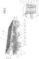
- Fig. 2 shows two similar pallets 1, which were initially stacked one inside the other, during the separation of these two pallets 1.
- the upper pallet 1 is lifted in an arcuate pivoting movement so that a hinge or pivot axis runs in the area of the front sides of the two pallets 1 on the right in the drawing.
- a person can stand in front of this front side, grasping the two long sides of the upper pallet 1 and lifting it off the lower pallet 1 in the pivoting movement shown.
- the feet 3 near this right front side are still partially stacked one inside the other.
- Fig. 2 It can be seen that the arcuate pivoting movement of the upper pallet 1 is carried out independently of any movement of the lower pallet 1, i.e. the lower pallet 1 still maintains its original orientation and is not also raised due to the movement of the upper pallet 1.
- the outer contour of the feet 3 tapers downwards in order to be able to stack the pallets 1 into each other and to allow the upper feet 3 to sink into the lower feet 3.
- Fig. 2 it is clear that the feet 3 closest to the front sides are tapered even more towards the middle of the pallet 1 and in their respective lower areas.
- this stronger taper is designed in the form of an inclined surface 12 and that these inclined surfaces 12 during the mentioned pivoting movement, a free space is formed between the two feet 3 stacked one inside the other, which allows the pivoting movement of the upper foot 3 independently of the lower foot 3 and prevents the two feet 3 from tilting.
- the supports 10 in the feet 3 near the front side also help to prevent tilting: they do not have a straight line towards the adjacent front side, which widens the support downwards, but rather a comparatively steep first section 14 near their upper end, and a comparatively slanted, i.e. flatter, second section 15 adjoining this downwards.
- this increases the stability of the support 10 by having the largest possible cross-section in its lower area, and on the other hand, the reduced upper cross-section offers the corresponding free space to enable the unhindered pivoting movement of the upper pallet 1 when separating the pallets 1.
- Fig.3 shows a view of the pallet 1 from below. It can be seen how the entry slopes 7 run from the edge 5 to the middle of the pallet deck 2. In particular, it can be seen that the entry slopes 7 on the long sides run at a smaller angle than the entry slopes 7 on the front sides. It can also be seen that the pallet deck 2 has a large number of intersecting webs which create a large number of rectangular openings 16 on the underside of the pallet deck 2. In the area of the entry slopes 7, some of the openings on the underside of the pallet deck 2 are closed, so that a closed surface of the pallet deck is created there, which guides the fork of an industrial truck when it comes into contact with this fork and acts as a deflector surface 17 to help prevent damage to the webs.
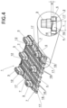
- Fig.4 shows the pallet 1 partially from below, with a vertical section through the pallet 1 in the area of two entry slopes 7. Where deflector surfaces 17 are created on the underside of the pallet deck 2 in the entry slopes 7, the upper side 4 of the pallet deck 2 has troughs 18. From the magnifying glass-like detail enlargement in Fig.4 It becomes clear that the angle of inclination of the entry slope 7 and thus of the deflector surface 17 is determined by the height H and the length L of the deflector surface 17. Fig.4 and in particular its enlarged detail shows a section through the entry slopes 7 on the long sides of the pallet 1. In comparison, the angle of inclination of the entry slopes 7 is greater: while the height H is the same there as on the long sides, the length L of the deflector surface 17 is smaller on the front sides than on the long sides.
- Fig.5 the different pitch angles of the longitudinal and frontal entry slopes 7 are visible. Furthermore, Fig.5 a plug-in element 19 which can be inserted from below into an opening 16 of the pallet deck 2.
- the plug-in element 19 is made of plastic and has been manufactured using a two-component injection molding process, with an assembly section 20 made of a comparatively harder plastic and a braking section 21 made of a comparatively softer plastic.
- the assembly section 20 ensures that the plug-in element 19 is securely held in the pallet deck 2, and the braking section 21 has a high coefficient of friction and projects downwards over the underside of the pallet deck 2 so that it comes into contact with the fork of an industrial truck and, due to its anti-slip effect, supports a secure hold of the pallet 1 on this fork.
- Fig.6 shows a view obliquely from above of the pallet 1, partially on the area of a corner of the pallet 1 and in a larger scale than Fig.1 .
- an RFID tag 22 is shown, which is a flat, flexible card This card can be elastically deformed and then inserted through the curved opening 11 into the compartment inside the nozzle 10. Due to the elastic recovery, the RFID tag is then held securely in the compartment.
Landscapes
- Engineering & Computer Science (AREA)
- Mechanical Engineering (AREA)
- Pallets (AREA)
- Stackable Containers (AREA)
Applications Claiming Priority (1)
| Application Number | Priority Date | Filing Date | Title |
|---|---|---|---|
| DE102023104070.7A DE102023104070A1 (de) | 2023-02-17 | 2023-02-17 | Mehrwegtransportpalette |
Publications (2)
| Publication Number | Publication Date |
|---|---|
| EP4417533A2 true EP4417533A2 (fr) | 2024-08-21 |
| EP4417533A3 EP4417533A3 (fr) | 2025-01-08 |
Family
ID=89983106
Family Applications (1)
| Application Number | Title | Priority Date | Filing Date |
|---|---|---|---|
| EP24158196.6A Withdrawn EP4417533A3 (fr) | 2023-02-17 | 2024-02-16 | Palette de transport à voies multiples |
Country Status (2)
| Country | Link |
|---|---|
| EP (1) | EP4417533A3 (fr) |
| DE (1) | DE102023104070A1 (fr) |
Family Cites Families (19)
| Publication number | Priority date | Publication date | Assignee | Title |
|---|---|---|---|---|
| SE328824B (fr) * | 1969-02-06 | 1970-09-21 | T Oertenblad | |
| FR2087251A5 (fr) * | 1970-05-13 | 1971-12-31 | Lallement Georges | |
| DE2358213A1 (de) * | 1973-11-22 | 1975-05-28 | Sanders | Palette |
| DE9218718U1 (de) * | 1991-07-17 | 1995-03-09 | Schoeller-Plast S.A., Romont | Teilpalette |
| EP0677448A3 (fr) * | 1994-04-12 | 1996-03-27 | Goldau Ursula | Palette en tÔle métallique. |
| JP3472463B2 (ja) * | 1997-11-26 | 2003-12-02 | 岐阜プラスチック工業株式会社 | 運搬用パレット |
| JP2001002069A (ja) * | 1999-06-21 | 2001-01-09 | Dainippon Ink & Chem Inc | 合成樹脂製パレット |
| US6220558B1 (en) * | 1999-08-26 | 2001-04-24 | Dell Usa, L.P. | Computer monitor stand |
| CN1248917C (zh) * | 2000-08-29 | 2006-04-05 | 大日本油墨化学工业株式会社 | 合成树脂货盘 |
| JP2006076605A (ja) * | 2004-09-09 | 2006-03-23 | Mc Trans International Inc | 運搬用パレット |
| DE102008014020B4 (de) * | 2008-03-13 | 2014-02-27 | Mf. Vertriebsgesellschaft Mbh | Transporteinrichtung, insbesondere Transportpalette |
| DE102009038963B4 (de) * | 2009-08-20 | 2020-06-10 | Dr. Doll Holding Gmbh | Stapelbarer Transportbehälter und Palettenboden aus Kunststoff hierfür |
| MX2012008754A (es) * | 2010-01-28 | 2012-11-29 | Pieter Wouter Du Toit | Paletas para el manejo de mercancias, procesos para fabricar paletas y metodos para utilizar paletas en el manejo de mercancias. |
| PL2357141T3 (pl) * | 2010-02-11 | 2013-05-31 | Becker Sp Z O O | Paleta |
| KR101206391B1 (ko) * | 2010-07-27 | 2012-11-29 | 리드메디 (주) | Rfid 태그가 수납되는 용기 |
| GB2504087A (en) * | 2012-07-16 | 2014-01-22 | Chep Uk Ltd | Pallet with feet which nest when stacking |
| JP5721091B1 (ja) * | 2014-08-03 | 2015-05-20 | 保雄 渡部 | パレット及び組立式コンテナ |
| ES2905581T3 (es) * | 2018-12-21 | 2022-04-11 | Viola Teres Josep Ramon | Pata para palé anidable y palé que comprende una pluralidad de patas |
| US11352169B2 (en) * | 2019-01-18 | 2022-06-07 | Rehrig Pacific Company | Pallet assembly |
-
2023
- 2023-02-17 DE DE102023104070.7A patent/DE102023104070A1/de active Pending
-
2024
- 2024-02-16 EP EP24158196.6A patent/EP4417533A3/fr not_active Withdrawn
Also Published As
| Publication number | Publication date |
|---|---|
| DE102023104070A1 (de) | 2024-08-22 |
| EP4417533A3 (fr) | 2025-01-08 |
Similar Documents
| Publication | Publication Date | Title |
|---|---|---|
| DE202013012291U1 (de) | Viertelpalette | |
| EP3636559B1 (fr) | Boîte empilable | |
| EP2552794B1 (fr) | Élément moulé pour le logement et la fixation de contenants de stockage de contour rectangulaire | |
| EP0301445A2 (fr) | Palette plate | |
| DE202014101556U1 (de) | Behälter für den Transport und die Lagerung von Gütern | |
| DE8536127U1 (de) | Stapelbarer Transportbehälter mit einklappbaren Wänden | |
| EP1024089B1 (fr) | Palette de transport | |
| EP4417533A2 (fr) | Palette de transport à voies multiples | |
| EP3941839B1 (fr) | Palette comprenant des butées d'empilement sur le plateau de palette | |
| EP0698558A2 (fr) | Récipient de transport empilable | |
| WO2005019048A1 (fr) | Porte-charge emboitable | |
| EP3632808A1 (fr) | Pallette en plastic | |
| EP1733975A1 (fr) | Contenant repliable | |
| CH673992A5 (fr) | ||
| DE102004053518B4 (de) | Mobilzaunfuß | |
| DE3934800A1 (de) | Stapeltransportkasten aus metallischem schichtmaterial | |
| DE19831640A1 (de) | Mehrweg-Transportbehälter | |
| EP4514702B1 (fr) | Récipient de grande capacité | |
| DE19525065C2 (de) | Kasten, insbesondere in Kreuzverbundstapelung | |
| DE202017106346U1 (de) | Träger- und Zwischenpalette | |
| DE10063281A1 (de) | Palette, insbesondere Kunststoff-Palette | |
| DE2731781B2 (de) | Stützfuß aus Kunststoff für Kartons o.dgl | |
| DE202008005632U1 (de) | Teilpalette | |
| DE10028588B4 (de) | Stapelbares Transportgebinde für stapelbares Stückgut | |
| DE8017829U1 (de) | Behaelter fuer den Transport gefaehrlicher Fluessigkeiten |
Legal Events
| Date | Code | Title | Description |
|---|---|---|---|
| PUAI | Public reference made under article 153(3) epc to a published international application that has entered the european phase |
Free format text: ORIGINAL CODE: 0009012 |
|
| STAA | Information on the status of an ep patent application or granted ep patent |
Free format text: STATUS: THE APPLICATION HAS BEEN PUBLISHED |
|
| AK | Designated contracting states |
Kind code of ref document: A2 Designated state(s): AL AT BE BG CH CY CZ DE DK EE ES FI FR GB GR HR HU IE IS IT LI LT LU LV MC ME MK MT NL NO PL PT RO RS SE SI SK SM TR |
|
| PUAL | Search report despatched |
Free format text: ORIGINAL CODE: 0009013 |
|
| AK | Designated contracting states |
Kind code of ref document: A3 Designated state(s): AL AT BE BG CH CY CZ DE DK EE ES FI FR GB GR HR HU IE IS IT LI LT LU LV MC ME MK MT NL NO PL PT RO RS SE SI SK SM TR |
|
| RIC1 | Information provided on ipc code assigned before grant |
Ipc: B65D 19/24 20060101AFI20241205BHEP |
|
| STAA | Information on the status of an ep patent application or granted ep patent |
Free format text: STATUS: THE APPLICATION IS DEEMED TO BE WITHDRAWN |
|
| 18D | Application deemed to be withdrawn |
Effective date: 20250709 |