EP4417879A1 - Haushaltsgerät - Google Patents
Haushaltsgerät Download PDFInfo
- Publication number
- EP4417879A1 EP4417879A1 EP24158034.9A EP24158034A EP4417879A1 EP 4417879 A1 EP4417879 A1 EP 4417879A1 EP 24158034 A EP24158034 A EP 24158034A EP 4417879 A1 EP4417879 A1 EP 4417879A1
- Authority
- EP
- European Patent Office
- Prior art keywords
- protrusion
- door
- door frame
- panel
- fitting
- Prior art date
- Legal status (The legal status is an assumption and is not a legal conclusion. Google has not performed a legal analysis and makes no representation as to the accuracy of the status listed.)
- Pending
Links
Images












Classifications
-
- F—MECHANICAL ENGINEERING; LIGHTING; HEATING; WEAPONS; BLASTING
- F24—HEATING; RANGES; VENTILATING
- F24C—DOMESTIC STOVES OR RANGES ; DETAILS OF DOMESTIC STOVES OR RANGES, OF GENERAL APPLICATION
- F24C15/00—Details
- F24C15/02—Doors specially adapted for stoves or ranges
-
- A—HUMAN NECESSITIES
- A47—FURNITURE; DOMESTIC ARTICLES OR APPLIANCES; COFFEE MILLS; SPICE MILLS; SUCTION CLEANERS IN GENERAL
- A47L—DOMESTIC WASHING OR CLEANING; SUCTION CLEANERS IN GENERAL
- A47L15/00—Washing or rinsing machines for crockery or tableware
- A47L15/42—Details
- A47L15/4251—Details of the casing
- A47L15/4257—Details of the loading door
- A47L15/4265—Arrangements of door covering/decoration panels or plinths, e.g. for integrated dishwashers
-
- D—TEXTILES; PAPER
- D06—TREATMENT OF TEXTILES OR THE LIKE; LAUNDERING; FLEXIBLE MATERIALS NOT OTHERWISE PROVIDED FOR
- D06F—LAUNDERING, DRYING, IRONING, PRESSING OR FOLDING TEXTILE ARTICLES
- D06F39/00—Details of washing machines not specific to a single type of machines covered by groups D06F9/00 - D06F27/00
- D06F39/12—Casings; Tubs
- D06F39/14—Doors or covers; Securing means therefor
-
- F—MECHANICAL ENGINEERING; LIGHTING; HEATING; WEAPONS; BLASTING
- F24—HEATING; RANGES; VENTILATING
- F24C—DOMESTIC STOVES OR RANGES ; DETAILS OF DOMESTIC STOVES OR RANGES, OF GENERAL APPLICATION
- F24C15/00—Details
- F24C15/02—Doors specially adapted for stoves or ranges
- F24C15/04—Doors specially adapted for stoves or ranges with transparent panels
-
- F—MECHANICAL ENGINEERING; LIGHTING; HEATING; WEAPONS; BLASTING
- F25—REFRIGERATION OR COOLING; COMBINED HEATING AND REFRIGERATION SYSTEMS; HEAT PUMP SYSTEMS; MANUFACTURE OR STORAGE OF ICE; LIQUEFACTION SOLIDIFICATION OF GASES
- F25D—REFRIGERATORS; COLD ROOMS; ICE-BOXES; COOLING OR FREEZING APPARATUS NOT OTHERWISE PROVIDED FOR
- F25D23/00—General constructional features
- F25D23/02—Doors; Covers
-
- F—MECHANICAL ENGINEERING; LIGHTING; HEATING; WEAPONS; BLASTING
- F25—REFRIGERATION OR COOLING; COMBINED HEATING AND REFRIGERATION SYSTEMS; HEAT PUMP SYSTEMS; MANUFACTURE OR STORAGE OF ICE; LIQUEFACTION SOLIDIFICATION OF GASES
- F25D—REFRIGERATORS; COLD ROOMS; ICE-BOXES; COOLING OR FREEZING APPARATUS NOT OTHERWISE PROVIDED FOR
- F25D2400/00—General features of, or devices for refrigerators, cold rooms, ice-boxes, or for cooling or freezing apparatus not covered by any other subclass
- F25D2400/18—Aesthetic features
Definitions
- the present disclosure relates to a home appliance, and more specifically, to a home appliance equipped with a door that opens and closes an inner space thereof.
- a home appliance such as a cooking appliance, a refrigerator, a laundry treating apparatus, etc., that has a door and accommodates an object in an inner space is widely used.
- the home appliance may include a cabinet constituting an outer appearance thereof and having a receiving space defined therein for accommodating the object therein, and a door for opening and closing the receiving space.
- the home appliance may include two or more doors as needed.
- the door of the home appliance is opaque. Therefore, when the door closes the receiving space, it is difficult to check the object received inside the receiving space. In the home appliance equipped with such a door, the door should be opened to check the object contained within the receiving space.
- the door of each of some home appliance such as an oven, a washing machine, a dryer, etc.
- the door of each of some home appliance may include a viewing window. As the viewing window is mounted on the door, a status of the object inside the home appliance may be checked through the viewing window.
- the door equipped with the viewing window may include a door frame constituting a frame of the door, a door glass mounted on the door frame, and a fixing structure for attaching the door glass to the door frame.
- An object of the present invention is to provide a home appliance with a structure improved such that a door panel constituting a front outer appearance of the door may be easily and quickly installed on the door and stably coupled to the door.
- another object of the present invention is to provide a home appliance with a structure improved so that damage to the door panel and the door panel may be suppressed during a door panel replacement process.
- Still another object of the present invention is to provide a home appliance with a structure improved so as to prevent a structure for installing the door panel on the door from deteriorating aesthetics of the door.
- a door panel coupled to the door frame to define an outer appearance of the door is coupled to the door frame via a fitting protrusion. Forward and backward movement of the panel body is restricted in a state in which a position of the fitting protrusion fitted with the door frame has been changed in a vertical direction.
- a door panel coupled to the door frame to define an outer appearance of the door is coupled to the door frame via a fitting protrusion and a fastening protrusion. Forward and backward movement of the panel body is restricted in a state in which a position of the fitting protrusion fitted with the door frame has been changed in a vertical direction.
- the fastening protrusion is coupled to the door frame to restrain upward and downward movement of the panel body.
- the door panel coupled to the door frame to define the outer appearance of the door is coupled to the door frame via a slidable fastening structure.
- a home appliance includes a body having an inner space defined therein; and a door configured to open and close the inner space, wherein the door includes a door frame disposed in front of the body, and a door panel disposed in front of the door frame, wherein the door panel includes: a panel body being disposed in front of the door frame and covering the door frame; a fitting protrusion fitted with the door frame to couple the panel body to the door frame; and a fastening protrusion disposed under the fitting protrusion and coupled to the door frame.
- the fitting protrusion fitted with the door frame is displaced upwardly or downwardly to prevent the panel body from moving forwardly or backwardly, wherein the fastening protrusion is coupled to the door frame to prevent the panel body from moving upwardly or downwardly.
- the door frame includes: a panel support surface portion constituting a front surface of the door frame; and a top protrusion disposed in front of the panel support surface portion, and spaced, by a predetermined spacing, from the panel support surface portion in a front-rear direction.
- At least a portion of the fitting protrusion is inserted into a fastening groove defined between the panel support surface portion and the top protrusion.
- the fitting protrusion includes: a rearwardly-extending protrusion portion protruding rearwardly from the panel body; and an upwardly-extending protrusion portion protruding upwardly from the rearwardly-extending protrusion portion.
- the upwardly-extending protrusion portion is inserted into the fastening groove.
- a top of the upwardly-extending protrusion portion protrudes upwardly beyond a top of the panel body.
- the panel body is disposed in front of the fitting protrusion so as to cover the fitting protrusion, wherein the top protrusion is inserted into a space surrounded with the panel body and the fitting protrusion.
- the door frame includes: a panel support surface portion constituting a front surface of the door frame; and a fitting hole extending through the panel support surface portion in a front-rear direction.
- the fitting protrusion includes: a protrusion body protruding rearwardly from the panel body; and a stopper portion protruding upwardly from the protrusion body.
- the stopper portion passes through the panel support surface portion through the fitting hole, wherein when the door panel moves upwardly, at least a portion of the stopper portion is located on top of the fitting hole so as to face a rear surface of the panel support surface portion.
- a recess is defined in the fitting protrusion and is positioned at a connection portion between the protrusion body and the stopper portion.
- the recess is formed in a shape in which at least one of a top surface of the protrusion body or a front surface of the stopper portion is concavely backwardly or downwardly depressed.
- the fitting protrusion has a curved portion constituting an edge connecting a rear surface and a top surface of the stopper portion to each other.
- the curved portion connects the rear surface and the top surface of the stopper portion to each other in a round shape.
- the door frame includes: a panel support surface portion constituting a front surface of the door frame; a top protrusion disposed in front of the panel support surface portion and spaced, by a predetermined spacing, from the panel support surface portion in a front-rear direction; and a fitting hole disposed between a lower end of the panel support surface portion and the top protrusion and formed so as to extend through the panel support surface portion in the front-rear direction.
- the door panel further includes a rib protruding from the panel body and disposed between the panel body and the panel support surface portion.
- the rib is in contact with the panel support surface portion when the door panel is coupled to the door frame.
- the fitting protrusion includes: a first fitting protrusion inserted into a fastening groove defined between the panel support surface portion and the top protrusion and fitted with the panel support surface portion; and a second fitting protrusion disposed between the first fitting protrusion and the fastening protrusion and fitted with the panel support surface portion through the fitting hole.
- the second fitting protrusion includes a pair of second fitting protrusions arranged horizontally and spaced from each other by a predetermined spacing, wherein the fitting protrusion further includes a third fitting protrusion disposed between the pair of second fitting protrusions and fitted with the panel support surface portion.
- the fitting protrusion includes a plurality of first fitting protrusions arranged horizontally and spaced from each other by a predetermined spacing, wherein a plurality of third fitting protrusions is positioned between the pair of second fitting protrusions.
- each of the third fitting protrusions is disposed between the first fitting protrusions adjacent to each other in a horizontal direction.
- the fitting protrusion includes a plurality of first fitting protrusions arranged horizontally and spaced from each other by a predetermined spacing.
- one of the plurality of first fitting protrusions disposed at a horizontal center of the door panel has a length in the horizontal direction larger than a length in the horizontal direction of each of remaining ones of the plurality of first fitting protrusions disposed at positions other than the horizontal center of the door panel.
- the fitting protrusion further includes a third fitting protrusion disposed between the first fitting protrusion and the fastening protrusion and fitted with the panel support surface portion.
- one of the plurality of first fitting protrusions disposed at the horizontal center of the door panel is disposed between the pair of third fitting protrusions that are horizontally spaced apart.
- the door frame includes: a first fastening groove defined so as to be recessed in a front surface of the door frame rearwardly; and a fastening boss disposed on top of the first fastening groove.
- the fastening protrusion is inserted into the first fastening groove so as to face the fastening boss in a vertical direction
- the home appliance further includes a fastener passing through the fastening protrusion and the fastening boss facing each other in the vertical direction to couple the fastening protrusion and the fastening boss to each other.
- the fastening boss is disposed on top of the first fastening groove, wherein the door panel includes a second fastening groove defined so as to be recessed upwardly in a bottom surface of the fastening protrusion.
- the fastener includes: a body passing through the fastening protrusion and the fastening boss; and a head connected to the body and exposed downwardly of the fastening boss, wherein the head is accommodated in the second fastening groove.
- the door frame includes a fitting hole recessed in a front surface of the door frame in a rearward direction, wherein the fastening protrusion is fitted with the door frame through the fitting hole.
- a bottom surface of the door frame and the fastening protrusion face each other in the vertical direction
- the home appliance further includes a fastener passing through the fastening protrusion and the bottom surface of the door frame facing each other in the vertical direction to couple the door frame and the fastening protrusion to each other.
- the door frame includes a fastening groove defined so as to be recessed upwardly in a bottom surface of the door frame; and a fastening boss disposed on top of the fastening groove, wherein the fastener includes a body passing through the fastening protrusion and the fastening boss, and a head connected to the body and exposed downwardly of the fastening boss, wherein the head is accommodated in the fastening groove.
- the home appliance further comprises a cap disposed under the head so as to cover the head, wherein the cap is inserted into the fastening groove.
- the outer appearance design of the door may be easily and efficiently changed, the installation of the door panel may be done easily and quickly, and the door panel may be stably coupled to the door.
- the door panel may be installed easily and quickly by pushing the door panel backwards and fitting the same with the door frame, and then pushing the door panel upwardly.
- various types of protrusions and fasteners may be used to stably couple the door panel to the door frame in various ways.
- the door panel may be installed by pushing the door panel backwards and fitting the same with the door frame, and then pushing the door panel upwardly.
- a force that may cause deformation or damage to the door panel or the door frame may not be applied thereto.
- the structure for installing the door panel on the door frame is not exposed to the outside out of the door, so that the structure for installing the door panel on the door frame does not damage the aesthetics of the door, thereby improving the aesthetics of the door.
- first, second, and the like are used to describe various components, these components are not limited by such terms. Such terms are only used to distinguish one component from another component, and unless specifically stated to the contrary, a first component may also be a second component.
- the present invention may not be limited to embodiments disclosed below, and various changes may be made and the present invention may be implemented in various different forms.
- the present embodiment is provided solely to ensure that the disclosure of the present invention is complete and to fully inform those skilled in the art of the scope of the invention. Therefore, it should be understood that the present invention is not limited to the embodiments disclosed below, but includes all changes, as well as substitution of components of one embodiment with components of another embodiment and addition of components.
- first component When a first component is described as being “connected” or “coupled” to a second component, it should be understood that the components may be directly connected or coupled to each other, but a third component may be interposed between the components. On the other hand, when it is described that the first component is “directly connected” or “directly coupled” to the second component, it should be understood that there are no other components interposed therebetween.
- first component When a first component is described to be "on top of' or “under” a second component, it is understood that the first component may be disposed in contact with a top surface or a bottom surface of the second component, as well as a third component may be interposed therebetween.
- a side on which a door is installed, relative to a center of the home appliance is defined as a front side. Therefore, a direction of opening the door and entering the home appliance becomes a rearward direction.
- a direction between the front side and a rear side may be referred to as a first direction.
- the front side may be referred to as one side in the first direction
- the rear side may be referred to as the other side in the first direction.
- direction of gravity may be defined as a downward direction, and a direction opposite to the direction of gravity may be defined as an upward direction.
- a horizontal direction orthogonal to the front and rear direction of the home appliance that is, a width direction of the home appliance when viewing the home appliance in front of the door thereof, may be referred to as a left and right direction.
- the left and right direction may be referred to as a second direction.
- a right side may be referred to as one side in the second direction
- a left side may be referred to as the other side in the second direction.
- a width direction of the home appliance may be referred to as a horizontal direction.
- a right side may be referred to as one side in the horizontal direction
- a left side may be referred to as the other side in the horizontal direction.
- the vertical direction described on top of may be referred to as a third direction.
- an upper side may be referred to as one side in the third direction, and a bottom may be referred to as the other side in the third direction.
- the vertical direction described on top of may be referred to as a height direction.
- the front and rear direction and the left and right direction, that is, the first direction and the second direction may be referred to as a transverse direction.
- a and/or B means A, B, or A and B, unless otherwise specified
- C to D means equal to or greater than C and equal to or smaller than D unless otherwise specified.
- FIG. 1 is a perspective view showing a home appliance according to an embodiment of the present invention
- FIG. 2 is a perspective view showing an open state of a cooking chamber of the home appliance as shown in FIG. 1 .
- a body 10 defines an outer appearance of the home appliance according to an embodiment of the present invention.
- the body 10 may be provided in a shape including a substantially hexahedral shape.
- This body 10 may be made of a material having a certain strength in order to protect a number of components installed in an inner space thereof.
- the body 10 may include a cavity 11.
- the cavity 11 may define a framework of the body 10.
- a receiving space 12 may be formed inside the cavity 11.
- the receiving space 12 may be in a form of a hexahedron with an open front surface.
- the home appliance may cook food by heating the receiving space 12.
- a door 100 that selectively opens and closes the receiving space 12 may be constructed to be pivotable.
- the door 100 may open and close the receiving space 12 using a pull-down manner in which an upper end thereof pivots upwardly and downwardly around a lower end thereof.
- the door 100 may be formed in an overall hexahedral shape with a predetermined thickness. Moreover, the door 100 may include a viewing window.
- the viewing window may be made of a transparent material, such as glass or transparent plastic. Depending on a type of the home appliance on which the viewing window is installed, the viewing window may need to be formed to withstand high temperature and pressure, and the viewing window may need functions such as waterproofing and heat dissipation.
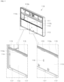
- FIG. 3 is a perspective view showing a door according to a first embodiment of the present invention
- FIG. 4 is a front exploded perspective view showing a disassembled state of the door as shown in FIG. 3 .
- a door 100 may include a door frame 110.
- the door frame 110 defines a framework of the door 100 and may constitute a top outer appearance, a bottom outer appearance, and a side outer appearance of the door 100.
- the door frame 110 may be formed in an approximately hexahedral shape.
- a hinge may be installed at a bottom of the door frame 110 to couple the door frame 110 to the body 10 so as to be pivotable.
- the hinge may be installed at a bottom of the door frame 110, but may be installed at each of both opposing sides of the door frame 110.
- the door 100 may further include a door glass G.
- the door glass G may be disposed in front of the door frame 110.
- the door glass G may be coupled to the door frame 110 while being disposed in front of the door frame 110 and may constitute a front outer appearance of the door 100.
- the door frame 110 may include a through-opening 112.
- the through-opening 112 may be formed to extend through the door frame 110 in a front-to-back direction.
- the door glass G may cover the through-opening 112 while being disposed in front thereof and may be coupled to the door frame 110. In this way, a state inside the receiving space 12 may be checked by a user in front of the door 100 through the door glass G provided on the door 100.
- the door 100 may further include a door panel 150.
- the door panel 150 may be disposed in front of the door frame 110 and may be coupled to the door frame 110 while being disposed in front of the door frame 110 and may constitute the front outer appearance of the door 100.
- the door glass G and the door panel 150 may be arranged in a vertical direction.
- the door panel 150 is illustrated as being disposed under the door glass G.
- the door panel 150 arranged in this way together with the door glass G may constitute the front outer appearance of the door 100.
- the door panel 150 may be detachably coupled to the door frame 110. Details regarding a coupling structure between the door panel 150 and the door frame 110 will be described later.
- the door 100 may further include a rear panel (not shown).
- the rear panel may be coupled to a rear side of the door frame 110 to constitute a rear portion of the door 100.
- a space surrounded with the door frame 110 and the rear panel may be defined.
- this inner space at least a portion of the hinge may be accommodated, and a damper, etc. to reduce a rotational speed of the door 100 may be accommodated.
- FIG. 5 is a front perspective view showing the separated door frame as shown in FIG. 4 .
- the door frame 110 may include a frame body 111.
- the frame body 111 may constitute the framework of the door frame 110.
- the frame body 111 may be formed in a substantially flat hexahedral shape.
- the through-opening 112 may be formed to extend through in the forward and backward directions.
- the frame body 111 may be formed in a rectangular ring shape.
- the door frame 110 may further include a panel support surface portion 113.
- the panel support surface portion 113 may constitute a front portion of the door frame 110.
- the panel support surface portion 113 may constitute a lower half of the front portion of the door frame 110.
- This panel support surface portion 113 may be disposed in front side of the frame body 111 and may be disposed under the through-opening 112.
- the panel support surface portion 113 may be disposed in rear of the door panel 150. This panel support surface portion 113 may support the door panel 150 while being in rear of the door panel 150. In one example, the panel support surface portion 113 may be formed in a rectangular plate shape.
- the door frame 110 may include a first fitting hole 114 and a second fitting hole 116.
- Each of the first fitting hole 114 and the second fitting hole 116 may be formed to extend through the panel support surface portion 113 in the forward and backward directions.
- the first fitting hole 114 may be constructed so that a second fitting protrusion 180 which will be described later may be inserted therein.
- the second fitting hole 116 may be constructed so that a third fitting protrusion 185, which will be described later may be inserted therein.
- first fitting hole 114 is disposed at each of both opposing ends of the panel support surface portion 113, and the second fitting hole 116 is disposed approximately in a center of the panel support surface portion 113. Moreover, in this embodiment, a plurality of first fitting holes 114 are arranged in a vertical direction at each end of the panel support surface portion 113.
- the door frame 110 may further include a door glass mount.
- the door glass mount may be disposed along a vertical outer edge of the panel support surface portion 113.
- the door glass mount includes a plurality of edge protrusions.
- Each edge protrusion may be formed to protrude from a vertical edge of the door frame 110 in a frontward direction.
- the door glass mount may include a lower edge protrusion 110a, an upper edge protrusion 110b, and a pair of side edge protrusions 1 10c.
- the lower edge protrusion 110a and the upper edge protrusion 110b may be arranged to be spaced apart from each other in a vertical direction while the through-opening 112 is disposed therebetween.
- the pair of side edge protrusions 110c may be arranged to be spaced apart from each other in a horizontal direction while the through-opening 112 is disposed therebetween.
- Each side edge protrusion 110c may extend in the vertical direction and connect the lower edge protrusion 110a and the upper edge protrusion 110b to each other.
- the upper edge protrusion 110b may be formed to protrude from an upper edge of the door frame 110 in the frontward direction.
- the pair of side edge protrusions 110c may be formed to respectively protrude from both opposing side edges of the door frame 110 in the frontward direction.
- the lower edge protrusion 110a may be disposed between the through-opening 112 and the panel support surface portion 113 and may be formed to protrude from a lower edge of the panel support surface portion 113 in the frontward direction Accordingly, a step may be formed between the door glass mount 110a and the panel support surface portion 113.
- the door glass G may be disposed in an inner area inwardly of the door glass mount, that is, an area surrounded with the lower edge protrusion 110a, the upper edge protrusion 110b, and the pair of side edge protrusions 110c. This door glass G may be installed into the door frame 110 so as to be fitted into the door glass mount in the inner area inwardly of the door glass mount.
- a bottom of the door glass G may be supported on a top of the door panel 150.
- the lower end of the door glass G may be supported on a rearwardly-extending protrusion portion 172 of a first fitting protrusion 170 which will be described later.
- the bottom of the door glass G may be supported on the lower edge protrusion 110a.
- the door frame 110 may further include a top protrusion 115.
- the top protrusion 115 may be disposed on a protrusion formed on an upper edge of the panel support surface portion 113, that is, the lower edge protrusion 110a. This top protrusion 115 may protrude downwardly from the lower edge protrusion 110a.
- the top protrusion 115 formed to protrude in this way may be disposed in front of the panel support surface portion 113.
- This top protrusion 115 may be spaced apart from the panel support surface portion 113 by a predetermined distance in the front and rear direction.
- a spacing between the top protrusion 115 and the panel support surface portion 113 may be set to correspond to a front-to-back thickness of an upwardly-extending protrusion portion 171 which will be described later.
- a fitting groove may be formed between the panel support surface 113 and the upper protrusion 115.
- the fitting groove is formed in the shape of a groove open downward, and the upper protrusion 171 is fitted into the fitting groove.
- the door frame 110 may include a plurality of top protrusions 115.
- the plurality of top protrusions 115 may be disposed on the door frame 110 and arranged horizontally and spaced from each other by at a predetermined spacing.
- the door frame 110 may further include a first fastening groove 117.
- the first fastening groove 117 may be disposed in a bottom of the door frame 110.
- the first fastening groove 117 may be constructed so that a fastening protrusion 190 which will be described later may be inserted therein.
- the first fastening groove 117 may be formed in a depressed shape in a bottom of a front portion of the door frame 110.
- the first fastening groove 117 may be concavely recessed rearwardly and may be formed to be concavely recessed upwardly in the bottom of the door frame 110.
- the first fastening groove 117 may be formed so as to be open downwardly and in a frontward direction.
- FIG. 6 is a rear perspective view showing a rear surface of the door panel as shown in FIG. 4 .
- the door panel 150 may include a panel body 160.
- the panel body 160 may constitute a framework and an outer appearance of the door panel 150.
- the panel body 160 may be coupled to the door frame 110 while being disposed in front of the door frame 110, and may be coupled to the panel support surface portion 113 while being disposed in front of the panel support surface portion 113.
- the panel body 160 is provided to cover the door frame 110 while being disposed in front thereof. More specifically, the panel body 160 is provided to cover the panel support surface portion 113 while being disposed in front thereof.
- This panel body 160 may be formed in a shape corresponding to a shape of the panel support surface portion 113. In one example, the panel body 160 may be formed in a rectangular plate shape.
- the panel body 160 may be formed to have various materials, colors, and designs.
- the door panel 150 having the panel body 160 may be constructed to be easily attached and detached to and from the front surface of the door frame 110. In other words, the door panel 150 may be easily replaced from the door 100, and thus, a material, a color, and a design of the front surface of the door 100 may be changed simply and efficiently.
- the door panel 150 may include a fastening structure to removably couple the door panel 150 and the door frame 110 to each other.
- this fastening structure may include the first fitting protrusion 170.
- the first fitting protrusion 170 may be disposed at a top of the door panel 150.
- the first fitting protrusion 170 may include the upwardly-extending protrusion portion 171 formed at the top of the door panel 150.
- the upwardly-extending protrusion portion 171 may be formed to protrude upwardly from the top of the door panel 150.
- the upwardly-extending protrusion portion 171 may be disposed at a position closer to a rear surface of the panel body 160 rather than to a front surface thereof. This upwardly-extending protrusion portion 171 may be formed to protrude backwardly from the top of the panel body 160 in a stepped shape.
- the upwardly-extending protrusion portion 171 may protrude upwardly and may be disposed at a position closer to a rear surface of the panel body 160 rather than to a front surface thereof. This upwardly-extending protrusion portion 171 and the panel body 160 may be connected to each other via the rearwardly-extending protrusion portion 172.
- the rearwardly-extending protrusion portion 172 may be formed to protrude rearwardly from the panel body 160.
- the upwardly-extending protrusion portion 171 may be formed to protrude upwardly from the rear end of the rearwardly-extending protrusion portion 172.
- the rearwardly-extending protrusion portion 172 connects the upper end of the panel body 160 and the lower end of the upwardly-extending protrusion portion 171 to each other.
- the rearwardly-extending protrusion portion 172 and the upwardly-extending protrusion portion 171 may be connected to each other in a "L" shape and may be disposed at the top of the panel body 160.
- the upwardly-extending protrusion portion 171 may be coupled to the top protrusion 115. This upwardly-extending protrusion portion 171 may be inserted into between the top protrusion 115 and the panel support surface portion 113 and may be coupled to the top protrusion 115.
- the door panel 150 may include a plurality of first fitting protrusions 170.
- the plurality of first fitting protrusions 170 may be arranged in a horizontal direction and may be spaced from each other by at a predetermined spacing and may be disposed on the door panel 150.
- the plurality of first fitting protrusions 170 may be arranged so as to be spaced from each other by a spacing corresponding to a spacing between adjacent ones of the plurality of top protrusions 115.
- the fastening structure for detachably coupling the door panel 150 and the door frame 110 to each other may further include the second fitting protrusion 180 on the door panel 150.
- the second fitting protrusion 180 may be disposed adjacent to a side of the door panel 150.
- the second fitting protrusion 180 may include a protrusion body 181 formed on the rear surface of the door panel 150.
- the protrusion body 181 may be formed to protrude rearwardly from the panel body 160.
- the second fitting protrusion 180 may further include a stopper portion 183.
- the stopper portion 183 may be formed to protrude upwardly or downwardly from a rear end of the protrusion body 181. In this embodiment, the stopper portion 183 is illustrated as protruding upwardly from the protrusion body 181.
- the second fitting protrusion 180 including the protrusion body 181 and the stopper portion 183 as described on top of may protrude backwardly from the panel body 160 and may extend in an approximately "L" shape.
- the second fitting protrusion 180 may be fitted with the door frame 110 through the first fitting hole 114 defined in the door frame 110.
- a plurality of second fitting protrusions 180 may be formed.
- the second fitting protrusions 180 are disposed at each of both opposing ends in a horizontal direction of the panel body 160, and are arranged vertically.
- the fastening structure for removably coupling the door panel 150 and the door frame 110 to each other may further include a third fitting protrusion 185 on the door panel 150.
- the second fitting protrusions 180 are disposed at each of both opposing ends of the door panel 150, and the third fitting protrusion 185 is disposed approximately at a center in the horizontal direction of the door panel 150.
- the third fitting protrusion 185 may be formed in a shape that protrudes rearwardly from the panel body 160, and may be formed in a shape similar to the second fitting protrusion 180.
- the third fitting protrusion 185 may be fitted with the door frame 110 through the second fitting hole 116 defined in the door frame 110.
- the second fitting protrusion 180 may be disposed at each of four corners of the door panel 150, and the third fitting protrusion 185 may be disposed approximately at the center in the horizontal direction of the door panel 150. That is, the third fitting protrusion 185 may be disposed between a pair of second fitting protrusions 180 spaced apart from each other in the horizontal direction, and at the same time, may be disposed between a pair of second fitting protrusions 180 spaced apart from each other in the vertical direction.
- the second fitting protrusion 180 and the third fitting protrusion 185 may be fitted with the door frame 110 through the first fitting hole 114 and the second fitting hole 116, respectively. Accordingly, the door panel 150 may be coupled to the door frame 110.
- the door panel 150 may be coupled to the door frame 110 at multiple points. That is, at the four corners and a central point of the door panel 150, the door panel 150 may be coupled to the door frame 110, so that the door panel 150 may be stably coupled to the door frame 110.
- the fastening structure for removably coupling the door panel 150 and the door frame 110 to each other may further include a fastening protrusion 190 on the door panel 150.
- the fastening protrusion 190 may be disposed at the bottom of the door panel 150.
- a fastening hole may be formed to extend through the fastening protrusion 190 in the vertical direction.
- the door panel 150 may further include a rib 161.
- the rib 161 may be formed to protrude rearwardly from the rear surface of the panel body 160.
- the ribs 161 are illustrated as being formed in a stripe shape and on the rear surface of the panel body 160. The rib 161 provided in this way may increase strength of the door panel 150 and may prevent the door panel 150 from being bent.
- the rib 161 may be disposed between the rear surface of the panel body 160 and the panel support surface portion 113 of the door frame 110.
- an anteroposterior length of the rib 161 may be set to a length corresponding to an anteroposterior spacing between the panel body 160 and the panel support surface portion 113.
- the rib 161 is in contact with the panel support surface portion 113 to maintain the spacing between the panel body 160 and the panel support surface portion 113.
- the rib 161 may support the door frame 150 so as to prevent the door panel 150 from being deformed in a depressed manner when the door panel 150 is pressed against the door frame 110 in order to couple the door panel 150 to the door frame 110.
- the rib 161 may stably support the door panel 150 to prevent the door panel 150 from being deformed in a depressed manner when the door panel 150 is pressed against the door frame 110.
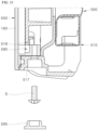
- FIG. 7 is a cross-sectional view showing a disassembled state of the door frame and the door panel as shown in FIG. 4
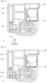
- FIG. 8 and FIG. 9 are cross-sectional views showing a first coupled state of the door frame and the door panel as shown in FIG. 7
- FIG. 10 and FIG. 11 are cross-sectional views showing a coupling-completed state of the door frame and the door panel as shown in FIG. 9 .
- the coupling between the door frame 110 and the door panel 150 may be achieved via coupling between the first fitting protrusion 170, the second fitting protrusion 180, the third fitting protrusion 185, and the fastening protrusion 190 of the door panel 150 and the door frame 110.
- the door panel 150 from a position in front of the door frame 110 may be displaced toward and coupled to the door frame 110.
- the second fitting protrusion 180 may pass through the panel support surface portion 113 in the forward and backward direction through the first fitting hole 114
- the third fitting protrusion 185 may pass through the panel support surface portion 113 in the forward and backward direction through the second fitting hole 116.
- the panel body 160 may be disposed in front of the panel support surface portion 113. While the rib 161 is in contact with the panel support surface portion 113, the door panel 150 may be seated on a front surface of the panel support surface portion 113. Further, the rear end of the protrusion body 181 and the stopper portion 183 may protrude rearwardly beyond the rear surface of the panel support surface portion 113, and the rear end of the third fitting protrusion 185 may protrude rearwardly beyond the rear surface of the panel support surface portion 113.
- the door panel 150 In a state in which the door panel 150 has been first coupled to the door frame 110, the door panel 150 is pushed upwardly as shown in FIG. 9 , such that the first fitting protrusion 170, the second fitting protrusion 180, and the third fitting protrusion 185 may be fitted into and coupled to the door frame 110.
- the stopper portion 183 of the second fitting protrusion 180 moves upwardly of the first fitting hole 114, such that the stopper portion 183 may face the rear surface of the panel support surface portion 113 in the front-to-back direction.
- the panel support surface portion 113 may be inserted into between the panel body 160 and the stopper portion 183, more specifically, between the rib 161 and the stopper portion 183. Accordingly, the fitting coupling between the door frame 110 and the protrusion body 181 may be achieved. In addition, the fitting coupling as shown above between the door frame 110 and the third fitting protrusion 185 may be achieved.
- the second fitting protrusion 180 may have a recess 182 defined therein.
- the recess 182 may be defined at a connection portion between the protrusion body 181 and the stopper portion 183.
- the recess 182 may be formed in a shape in which a front surface of the stopper portion 183 facing the rear surface of the panel body 160 is concavely recessed rearwardly.
- the recess 182 may be formed in a shape in which a top surface of the protrusion body 181 is concavely recessed downwardly. In still another example, the recess 182 may be formed in a shape in which a front surface of the stopper portion 183 is concavely recessed backwardly and at time same time, the top surface of the protrusion body 181 is concavely recessed downwardly.
- the stopper portion 183 is connected to the protrusion body 181 at a right angle relative to the protrusion body 181, and the stopper portion 183 may constitute a vertical wall extending parallel to the rib 181.
- the panel support surface portion 113 may be inserted into between the stopper portion 183 and the rib 161.
- the second fitting protrusion 180 is formed such that an angle defined between the stopper portion 183 and the protrusion body 181 is slightly larger or smaller than the right angle.
- the recess 182 is formed in the second fitting protrusion 180.
- the recess 182 defined in the second fitting protrusion 180 may allow an amount by which the stopper portion 183 is bent around the connection portion between the protrusion body 181 and the stopper portion 183 to be increased. That is, an elastic bent deformation amount of the stopper portion 183 may be increased due to the recess 182 defined in the second fitting protrusion 180.
- interference may occur between the panel support surface portion 113 and a portion of the protrusion body 181 when the second fitting protrusion 180 passes through the first fitting hole 114.
- the stopper portion 183 is elastically bent, such that the second fitting protrusion 180 may easily pass through the first fitting hole 114.
- a gap between the stopper portion 183 and the rib 161 may be smaller than the thickness of the panel support surface portion 113.
- the stopper portion 183 is bent elastically, such that the panel support surface portion 113 may be inserted into between the stopper portion 183 and the rib 161.
- the stopper portion 183 may have a curved portion 184.
- the curved portion 184 may be disposed along an edge connecting the rear surface and the top surface of the stopper portion 183 to each other, and an adjacent area to the edge.
- This curved portion 184 may constitute a curved surface connecting the rear surface and the top surface of the stopper portion 183 to each other in a rounded manner.
- the curved portion 184 formed in this way may allow the stopper portion 183 to smoothly pass through the first fitting hole 114 when the second fitting protrusion 180 passes through the panel support surface portion 113 through the first fitting hole 114.
- the features such as the recess 182 and the curved portion 184 as described on top of may be applied only to the second fitting protrusion 180 and/or may also be equally applied to the third fitting protrusion 185. In this embodiment, it is illustrated that the features such as the recess 182 and the curved portion 184 are applied to the third fitting protrusion 185 as well as the second fitting protrusion 180.
- an anteroposterior position of the door panel 150 with respect to the door frame 110 may be restrained.
- the coupling of the second fitting protrusion 180 and the third fitting protrusion 185 to the door frame 110 may be achieved in a press-fitting manner. In this case, a vertical directional movement of the door panel 150 relative to the door frame 110 may be restrained.
- first fitting protrusion 170 and the top protrusion 115 may be coupled to each other at the top of the door panel 150. As shown in FIG. 9 and FIG. 10 , when the door panel 150 is pushed upwardly while the door panel 150 has been first coupled to the door frame 110, the upwardly-extending protrusion portion 171 of the first fitting protrusion 170 may be positioned so as to face the rear surface of the top protrusion 115 in the anteroposterior direction.
- the upwardly-extending protrusion portion 171 may be inserted into the fitting groove formed between the panel support surface portion 113 and the top protrusion 115, and thus the fitting coupling between the door frame 110 and the upwardly-extending protrusion portion 171 may be achieved. Due to the fitting coupling between the door frame 110 and the upwardly-extending protrusion portion 171 as described above, the upper end of the door panel 150 may be detachably coupled to the door frame 110.
- a coupling between the fastening protrusion 190 and the first fastening groove 117 may be achieved.
- the fastening protrusion 190 may be inserted into the first fastening groove 117.
- the first fastening groove 117 may be formed in an upwardly recessed manner from a bottom, that is, may be open downwardly, and further, may be open in the frontward direction.
- the fastening protrusion 190 positioned under the first fastening groove 117 may move upwardly along the door panel 150 when the door panel 150 is pushed upwardly and then may be inserted into the first fastening groove 117.
- a portion of the first fastening groove 117 open in the frontward direction may provide a passage necessary for upward movement of a connection portion between the fastening protrusion 190 and the panel body 160.
- the first fastening groove 117 may be formed so as to be open toward a position in front of the door frame 110, that is, in the frontward direction.
- the portion of the first fastening groove 117 formed in the door frame 110 is open in the frontward direction, such that the fastening protrusion 190 and the first fastening groove 117 may be engaged with each other via the upward movement of the door panel 150.
- the coupling between the fastening protrusion 190 and the first fastening groove 117 in this embodiment may be achieved via the upward movement of the door panel 150.
- the door panel 150 does not need to pivot forwardly or backwardly around the top of the door panel 150.
- the fastening protrusion 190 may be inserted into the first fastening groove 117 and may be coupled to the bottom of the door frame 110. In this regard, the fastening protrusion 190 may be in contact with a top surface of the first fastening groove 117.
- the door frame 110 may have a fastening boss 118.
- the fastening boss 118 may be disposed on top of the first fastening groove 117.
- This fastening boss 118 may have a fastening hole defined therein so as to extend through the boss 118 in the vertical direction.
- the fastening hole formed in the fastening protrusion 190 and the fastening hole formed in the fastening boss 118 may communicate with each other in the vertical direction.
- the fastening protrusion 190 and the door frame 110 may be fastened to each other via a fastener S such as a screw
- the fastener S may extend through the fastening protrusion 190, the first fastening groove 117, and the fastening boss 118 and may fasten the fastening protrusion 190 and the door frame 110 to each other. A portion of the fastener S protruding out of the fastening protrusion 190 may be received in the second fastening groove 192.
- the fastener S may be embodied as a screw including a body and a head.
- the body of the screw may pass through the first fastening groove 117 and the fastening boss 118.
- the head may be a portion connected to the body and protruding downwardly beyond the fastening boss 118.
- the door panel 150 may be removably coupled to the door frame 110 using the first fitting protrusion 170, the second fitting protrusion 180, the third fitting protrusion 185, and the fastening protrusion 190.
- This door panel 150 may be first coupled to the door frame 110 using the first fitting protrusion 170, the second fitting protrusion 180, and the third fitting protrusion 185. Then, the door panel 150 may be firmly fixed to the door frame 110 by fastening the fastening protrusion 190 to the door frame 110 using the fastener S.
- the door panel 150 may be easily and quickly coupled to the door frame 110 by an operator pushing the door panel 150 backwards and fitting the door panel 150 into the door frame 110 and then pushing the door panel 150 upwardly.
- the door panel 150 may be stably coupled to the door frame 110 in various ways using various types of protrusions and fasteners.
- the door panel 150 may be stably fitted with the door frame 110 by fitting the door panel into the door frame 110 in the front and rear direction and then simply moving the door panel upwardly without having to pivot the door panel in the front and rear direction.
- the door panel 150 may be installed efficiently even in a narrow space where it is difficult to pivot the door panel 150 forwards and backwards.
- the door panel 150 may be installed simply on the door frame 110 by simply fastening the fastener S to the door frame in a state in which the door panel 150 has been easily and efficiently first fitted into the door frame 110.
- the door panel 150 may be easily removed from the door frame 110 by simply unscrewing the fastener S that has screw-coupled the door panel 150 and the door frame 110 to each other.
- the outer appearance design of the door 100 may be changed simply and efficiently.
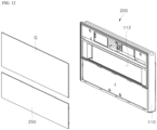
- FIG. 12 is an exploded perspective view showing a disassembled state of the door according to the second embodiment of the present invention
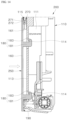
- FIG. 13 is a cross-sectional view showing a disassembled state of the door frame and the door panel as shown in FIG. 12
- FIG. 14 and FIG. 15 are cross-sectional views showing a first coupled state of the door frame and the door panel as shown in FIG. 13
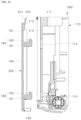
- FIG. 16 and FIG. 17 are cross-sectional views showing a coupling-completed state of the door frame and the door panel as shown in FIG. 15 .
- a main difference between the door illustrated in the preceding embodiment and a door 200 according to the second embodiment of the present invention relates to a first fitting protrusion 270 of a door panel 250.
- the first fitting protrusion 270 is disposed on the rear surface of the panel body 160 and does not protrude upwardly beyond the panel body 160.
- the first fitting protrusion 270 may include a L-shape portion 271 protruding rearwardly and then upwardly while being disposed in rear of the panel body 160.
- a first fastening groove 272 may be defined by the first fitting protrusion 270.
- the first fastening groove 272 may be defined as a space surrounded with the L-shaped portion 271 formed as described on top of and the panel body 160.
- the top protrusion 115 may be inserted into the first fastening groove 272, such that the door panel 250 may be coupled to the top protrusion 115 in a fitting manner.
- the door panel 250 may cover the top protrusion 115 while being disposed in front of the top protrusion 115 and may be coupled to the top protrusion 115. That is, in this embodiment, when the door panel 250 is coupled to the door frame 110, the door panel 250 may cover the top protrusion 115 while being disposed in front of the top protrusion 115 to prevent the top protrusion 115 from being exposed to an outside out of the door 200.
- the door panel 250 of this embodiment configured in this way may prevent a structure for installing the door panel 110 to the door 200, such as the top protrusion 115, from being exposed to the outside out of the door, thereby improving aesthetics of the door 200.
- FIG. 18 is an exploded perspective view showing a disassembled state of the door according to the third embodiment of the present invention.
- FIG. 19 is a perspective view showing the separated door panel as shown in FIG. 18 .
- FIG. 20 is a cross-sectional view showing a disassembled state of the door frame and the door panel as shown in FIG. 18 .
- FIG. 21 and FIG. 22 are cross-sectional views showing a first coupled state of the door frame and the door panel as shown in FIG. 20 .
- FIG. 23 and FIG. 24 are cross-sectional views of a coupling-completed state of the door frame and the door panel as shown in FIG. 22 .
- a main difference between the door illustrated in the preceding embodiments and a door 300 according to the third embodiment of the present invention relates to a first fitting protrusion 370 of a door panel 350.
- the first fitting protrusion 370 of this embodiment may include a L-shaped portion 371 protruding upwardly beyond the top of the panel body 160.
- the L-shaped portion 371 of this embodiment is different from the first upwardly-extending protrusion portion 171 (see FIG. 7 ) illustrated in the first embodiment of the present invention in that the L-shaped portion 371 of this embodiment has an integrated structure.
- the L-shaped portion 371 provided in this way may contribute to allowing the top of the door panel 350 to be more stably supported on the door frame 110 and to allowing the door panel 350 to be stably coupled to the door frame 110.
- FIG. 25 is a front perspective view showing the door according to the fourth embodiment of the present invention.
- FIG. 26 is a front exploded perspective view showing a disassembled state of the door as shown in FIG. 25 .
- FIG. 27 is a front perspective view showing a separated door frame as shown in FIG. 25 .
- FIG. 28 is a rear perspective view showing a rear surface of the door panel as shown in FIG. 25 .
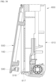
- FIG. 29 is a cross-sectional view showing a coupled state of the door frame and the door panel as shown in FIG. 25 .
- FIG. 30 is an enlarged view showing a top coupled state of the door frame and the door panel as shown in FIG. 29 .
- FIG. 31 is an enlarged view showing a bottom coupled state of the door frame and the door panel as shown in FIG. 29 .
- a main difference between the door illustrated in the above-described embodiments and a door 400 according to the fourth embodiment of the present invention relates to a top protrusion 415 of a door frame 410, and a first fitting protrusion 470 and 470a and a third fitting protrusion 185 of a door panel 450.
- top protrusion 415 of this embodiment has an integrated structure.
- the top protrusion 415 of the present embodiment may more stably support the first fitting protrusion 470 and 470a inserted into between the panel support surface portion 113 and the top protrusion 415, such that the top of the door panel 450 may be more stably supported on the door panel 410 and the door panel 450 may be stably coupled to the door frame 410.
- first fitting protrusion 470 and 470a of this embodiment may be disposed at the top of the door panel 450, like the first fitting protrusion 170 (see FIG. 6 ) illustrated in the first embodiment of the present invention. Moreover, at the top of the door panel 450, a plurality of first fitting protrusions 470 and 470a may be arranged so as to be spaced from each other by at a predetermined spacing along the horizontal direction.
- the first fitting protrusion 470a (hereinafter referred to as "central protrusion") disposed at a horizontal center of the door panel 450 among the plurality of first fitting protrusions 470 and 470a may have a length in the horizontal direction larger than that of the first fitting protrusion 470 disposed at a position other than the horizontal center of the door panel 450 among the plurality of first fitting protrusions 470 and 470a.
- central protrusion 470a which has the horizontal length larger than that of the first fitting protrusion 470 is disposed at the horizontal center of the door panel 450, a center of the top of the door panel 450 may be supported more stably on the door frame 410.
- each of both horizontally opposing ends of the door panel 450 may be coupled to the door frame 410 via the first fitting protrusion 470, and further, via the plurality of second fitting protrusions 180 arranged in the vertical direction. That is, each of both horizontally opposing ends the door panel 450 may coupled to the door frame 410 via the fitting protrusions at three or more points and the fastening protrusion 490 and thus be firmly supported on the door frame 410.
- the horizontal center of the door panel 450 may be coupled to the door frame 410 only via the central protrusion 470a. That is, the horizontal center of the door panel 450 may be coupled to the door frame 410 at only one point, except for a coupling point corresponding to the fastening protrusion 190.
- the horizontal center of the door panel 450 may be likely to be less firmly supported on the door frame 410 than each of the both horizontally opposing ends of the door panel 450 may be.
- the central protrusion 470a having the larger horizontal length than that of the first fitting protrusion 470 is disposed at the horizontal center of the door panel 450.
- the central protrusion 470a having this feature may contribute to allowing the center of the top of the door panel 450 to be more stably supported on the door frame 410.
- the door frame 410 of this embodiment may include a plurality of third fitting protrusions 185.
- the plurality of third fitting protrusions 185 may be arranged horizontally and spaced from each other by a predetermined spacing.
- Each of the third fitting protrusions 185 may be disposed between the first fitting protrusion 470 and 470a and the fastening protrusion 190 in the vertical direction. In the horizontal direction, each of the third fitting protrusions 185 may be disposed between the first fitting protrusions 470 and 470a adjacent to each other. For example, in a specific area of the door frame 410, the first fitting protrusions 470 and 470a and the third fitting protrusions 185 may be arranged alternately with each other along the horizontal direction.
- a pair of third fitting protrusions 185 may be disposed under the central protrusion 470a, and may be arranged so as to be spaced from each other by a predetermined spacing horizontally while the central protrusion 470a is disposed therebetween.
- the plurality of third fitting protrusion 185 arranged as above may allow the central area of the door panel 450 to be coupled to the door panel 450 at multiple points, so that the central area of the door panel 450 may be supported more stably on the door frame 410.
- the plurality of third fitting protrusions 185 as described on top of may be arranged so as to be spaced from each other by a predetermined spacing horizontally while the central protrusion 470a is disposed therebetween.
- Each of the plurality of third fitting protrusions 185 may be coupled to the door frame 410 at a point between a point where the central protrusion 470a and the door frame 410 are coupled to each other and a point where the second fitting protrusion 180 and the door frame 410 are coupled to each other.
- the third fitting protrusions 185 may be respectively disposed at a point between the horizontal center of the door panel 450 and each of both horizontally opposing ends of the door panel 450 where the coupling between the door panel 450 and the door frame 410 is stable, and a point between each of the first fitting protrusions 470 and 470a and the fastening protrusion 190, and may be coupled to the door frame 410.
- the third fitting protrusions 185 coupled to the door frame 410 in this way may contribute to allowing an entire area of the door panel 450 including a central area in the vertical direction of the door panel 450 to be more stably supported on the door frame 410. support.
- FIG. 32 is a front perspective view showing a door according to a fifth embodiment of the present invention.
- FIG. 33 is a cross-sectional view showing a first coupled state of a door frame and a door panel as shown in FIG. 32 .
- FIG. 34 is a cross-sectional view showing a coupling-completed state of the door frame and the door panel as shown in FIG. 33 .
- FIG. 35 is a front perspective view showing a door according to a sixth embodiment of the present invention.
- FIG. 36 is a cross-sectional view showing a first coupled state of a door frame and a door panel as shown in FIG. 35 .
- FIG. 37 is a cross-sectional view showing a coupling-completed state of the door frame and the door panel as shown in FIG. 36 .
- FIG. 38 to FIG. 40 are cross-sectional views showing a coupling process of the door frame and the door panel to each other.
- a door panel 550 may include a fastening protrusion 590.
- the door panel 550 of this embodiment may further include the first fitting protrusion, the second fitting protrusion, and the third fitting protrusion illustrated in the above-described embodiment.
- the door panel 550 may include any one of the various types of first fitting protrusions illustrated in the above-described embodiments.
- the fastening protrusion 590 may protrude rearwardly from the panel body 160, and may be disposed at a position slightly spaced upwardly from the bottom of the panel body 160. This fastening protrusion 590 may be disposed on top of a first fastening groove 517.
- the fastening protrusion 590 may be disposed on top of the first fastening groove 517 and may face the first fastening groove 517 in the vertical direction when the door panel 550 has been first coupled to the door frame 510.
- a third fitting hole 518 may be defined in the door frame 510.
- the third fitting hole 518 may be formed to extend through the panel support surface portion 113 in the front-to-back direction.
- the third fitting hole 518 may be constructed so that the fastening protrusion 590 may be inserted therein.
- the number of the third fitting holes 518 may correspond to the number of the fastening protrusions 590.
- the third fitting holes 518 may be arranged so as to be spaced from each other by a spacing corresponding to a spacing between the fastening protrusions 590.
- Each of the third fitting holes 518 may be disposed adjacent to a bottom of the panel support surface portion 113.
- the third fitting hole 518 is illustrated as being disposed on top of the first fastening groove 517.
- Each fastening protrusion 590 may be fitted with the door frame 510 through the third fitting hole 518 and may be disposed so as to face the first fastening groove 517 in the vertical direction and in the door frame 510.
- fastening protrusion 590 and the first fastening groove 517 face each other in the vertical direction
- fastening protrusion 590 and the door frame 110 may be fastened to each other via a fastener S.
- a portion (for example, a head of a screw) of the fastener S exposed to an outside out of the fastening protrusion 590 may be accommodated in the first fastening groove 517.
- the door 500 of this embodiment may further include a cap 595.
- the cap 595 may be inserted into the first fastening groove 517 through an open bottom of the first fastening groove 517, as shown in FIG. 34 .
- the cap 595 inserted into the first fastening groove 517 may cover the head of the fastener S while being disposed thereunder and may be inserted into the first fastening groove 517.
- the cap 595 may be provided as a finishing material that covers an area in which the fastening protrusion 590 and the door frame 110 are coupled to each other. Due to the cap 595, the aesthetics of the door 500 may be more effectively improved.
- a first fastening groove 617 provided at the bottom of the door frame 610 may be provided in a depressed form having a relatively shallow depth compared to a depth of the fastening groove 517 illustrated in the fifth embodiment of the present invention.
- a door 600 may be free of a cap.
- the door panel 550 may be installed on the door frame 510 in a following manner.
- the door panel 550 may be coupled to the door frame 510 while being in front of the door frame 510.
- first fitting protrusion For the coupling between the door frame 510 and the door panel 550, a coupling between the first fitting protrusion and the top protrusion 115 (see FIG. 10 ) may first be achieved.
- the first fitting protrusion may be selected as one of the first fitting protrusions as illustrated in the first to third embodiments of the present invention.
- the coupling between the first fitting protrusion and the top protrusion 115 may be achieved by moving the first fitting protrusion in an inclined manner toward the top protrusion 115 so as to be fitted with the top protrusion 115.
- the first fitting protrusion fitted with the top protrusion 115 in the inclined manner may pivot backwards around a top thereof fitted with the top protrusion 115 such that the first fitting protrusion is inserted into between the panel support surface portion 113 and the top protrusion 115. Accordingly, a fitting coupling between the door frame 510 and the first fitting protrusion may be achieved.
- the door panel 550 may pivot rearwardly around the first fitting protrusion, such that the second fitting protrusion 180 and the third fitting protrusion 185 are inserted into the first fitting hole 114 (see FIG. 5 ) and the second fitting hole 116 (see FIG. 5 ), respectively.
- the couplings between the second fitting protrusion 180 and the third fitting protrusion 185 and the door frame 510 may be achieved together.
- a coupling between the fastening protrusion 590 and the first fastening groove 117 may be made.
- the coupling between the fastening protrusion 590 and the first fastening groove 117 may be achieved using the fastener S.
Landscapes
- Engineering & Computer Science (AREA)
- Chemical & Material Sciences (AREA)
- Combustion & Propulsion (AREA)
- Mechanical Engineering (AREA)
- General Engineering & Computer Science (AREA)
- Civil Engineering (AREA)
- Structural Engineering (AREA)
- Securing Of Glass Panes Or The Like (AREA)
Applications Claiming Priority (2)
| Application Number | Priority Date | Filing Date | Title |
|---|---|---|---|
| KR20230021763 | 2023-02-17 | ||
| KR1020230173655A KR20240128555A (ko) | 2023-02-17 | 2023-12-04 | 가전기기 |
Publications (1)
| Publication Number | Publication Date |
|---|---|
| EP4417879A1 true EP4417879A1 (de) | 2024-08-21 |
Family
ID=89983878
Family Applications (1)
| Application Number | Title | Priority Date | Filing Date |
|---|---|---|---|
| EP24158034.9A Pending EP4417879A1 (de) | 2023-02-17 | 2024-02-16 | Haushaltsgerät |
Country Status (2)
| Country | Link |
|---|---|
| US (1) | US20240279981A1 (de) |
| EP (1) | EP4417879A1 (de) |
Citations (4)
| Publication number | Priority date | Publication date | Assignee | Title |
|---|---|---|---|---|
| JP2016156556A (ja) * | 2015-02-24 | 2016-09-01 | シャープ株式会社 | 冷却室用扉 |
| WO2020213861A1 (en) * | 2019-04-15 | 2020-10-22 | Samsung Electronics Co., Ltd. | Refrigerator |
| KR20220068124A (ko) * | 2020-11-18 | 2022-05-25 | 삼성전자주식회사 | 냉장고 |
| WO2022142287A1 (zh) * | 2020-12-31 | 2022-07-07 | Tcl家用电器(合肥)有限公司 | 门体结构、及其安装方法 |
Family Cites Families (6)
| Publication number | Priority date | Publication date | Assignee | Title |
|---|---|---|---|---|
| GB8510241D0 (en) * | 1985-04-22 | 1985-05-30 | Int Computers Ltd | Equipment cabinets & housings |
| US6736470B2 (en) * | 2001-10-05 | 2004-05-18 | Maytag Corporation | Molded plastic dishwasher door assembly |
| CN107328161A (zh) * | 2017-08-25 | 2017-11-07 | 合肥联宝信息技术有限公司 | 安装组件、冰箱门及冰箱 |
| KR102312667B1 (ko) * | 2019-04-15 | 2021-10-15 | 삼성전자주식회사 | 냉장고 |
| EP4621329A3 (de) * | 2020-05-28 | 2025-10-29 | LG Electronics Inc. | Kühlschrank |
| EP3926271B1 (de) * | 2020-06-17 | 2023-05-03 | LG Electronics Inc. | Kühlschrank |
-
2024
- 2024-02-16 EP EP24158034.9A patent/EP4417879A1/de active Pending
- 2024-02-16 US US18/444,076 patent/US20240279981A1/en active Pending
Patent Citations (4)
| Publication number | Priority date | Publication date | Assignee | Title |
|---|---|---|---|---|
| JP2016156556A (ja) * | 2015-02-24 | 2016-09-01 | シャープ株式会社 | 冷却室用扉 |
| WO2020213861A1 (en) * | 2019-04-15 | 2020-10-22 | Samsung Electronics Co., Ltd. | Refrigerator |
| KR20220068124A (ko) * | 2020-11-18 | 2022-05-25 | 삼성전자주식회사 | 냉장고 |
| WO2022142287A1 (zh) * | 2020-12-31 | 2022-07-07 | Tcl家用电器(合肥)有限公司 | 门体结构、及其安装方法 |
Also Published As
| Publication number | Publication date |
|---|---|
| US20240279981A1 (en) | 2024-08-22 |
Similar Documents
| Publication | Publication Date | Title |
|---|---|---|
| KR102280927B1 (ko) | 오븐 | |
| KR101602666B1 (ko) | 세탁물 처리기기 | |
| CN113100639B (zh) | 烹饪设备 | |
| CN111519409B (zh) | 衣物处理装置 | |
| EP3658825B1 (de) | Ofen | |
| EP2634494B1 (de) | Kochvorrichtung | |
| EP4417879A1 (de) | Haushaltsgerät | |
| EP3819573B1 (de) | Kühlschrank | |
| KR102351995B1 (ko) | 냉장고 | |
| CN211818667U (zh) | 一种用于烹饪设备门体上的把手组件及门体 | |
| KR20230010887A (ko) | 에어벤트의 윙 노브 장치 | |
| EP4317791B1 (de) | Gargerät | |
| CN111411486A (zh) | 衣物处理设备 | |
| CN115404664B (zh) | 一种壁挂式衣物处理设备及其前封门组件 | |
| CN118517214A (zh) | 家用电器 | |
| CN111411849B (zh) | 炉门组件和烹饪器具 | |
| CN216517559U (zh) | 一种家用电器门结构及烹饪设备 | |
| CN210931013U (zh) | 食物处理器基座和料理机 | |
| KR20240128555A (ko) | 가전기기 | |
| CN207963098U (zh) | 空调器的壳体组件及空调器 | |
| CN218763927U (zh) | 空调器 | |
| CN113905473B (zh) | 烹饪器具 | |
| KR102329141B1 (ko) | 전기 가열조리기의 뚜껑열림 버튼 어셈블리 | |
| CN215687073U (zh) | 烹饪器具 | |
| EP4474715A1 (de) | Kochgerät |
Legal Events
| Date | Code | Title | Description |
|---|---|---|---|
| PUAI | Public reference made under article 153(3) epc to a published international application that has entered the european phase |
Free format text: ORIGINAL CODE: 0009012 |
|
| STAA | Information on the status of an ep patent application or granted ep patent |
Free format text: STATUS: REQUEST FOR EXAMINATION WAS MADE |
|
| 17P | Request for examination filed |
Effective date: 20240316 |
|
| AK | Designated contracting states |
Kind code of ref document: A1 Designated state(s): AL AT BE BG CH CY CZ DE DK EE ES FI FR GB GR HR HU IE IS IT LI LT LU LV MC ME MK MT NL NO PL PT RO RS SE SI SK SM TR |