EP4417932A1 - Guidage sécurisé d'un câble sur un sous-marin - Google Patents
Guidage sécurisé d'un câble sur un sous-marin Download PDFInfo
- Publication number
- EP4417932A1 EP4417932A1 EP24156600.9A EP24156600A EP4417932A1 EP 4417932 A1 EP4417932 A1 EP 4417932A1 EP 24156600 A EP24156600 A EP 24156600A EP 4417932 A1 EP4417932 A1 EP 4417932A1
- Authority
- EP
- European Patent Office
- Prior art keywords
- underwater
- floating body
- connection
- connection unit
- submarine
- Prior art date
- Legal status (The legal status is an assumption and is not a legal conclusion. Google has not performed a legal analysis and makes no representation as to the accuracy of the status listed.)
- Granted
Links
Images

Classifications
-
- F—MECHANICAL ENGINEERING; LIGHTING; HEATING; WEAPONS; BLASTING
- F41—WEAPONS
- F41F—APPARATUS FOR LAUNCHING PROJECTILES OR MISSILES FROM BARRELS, e.g. CANNONS; LAUNCHERS FOR ROCKETS OR TORPEDOES; HARPOON GUNS
- F41F3/00—Rocket or torpedo launchers
- F41F3/08—Rocket or torpedo launchers for marine torpedoes
- F41F3/10—Rocket or torpedo launchers for marine torpedoes from below the surface of the water
-
- F—MECHANICAL ENGINEERING; LIGHTING; HEATING; WEAPONS; BLASTING
- F41—WEAPONS
- F41G—WEAPON SIGHTS; AIMING
- F41G7/00—Direction control systems for self-propelled missiles
- F41G7/20—Direction control systems for self-propelled missiles based on continuous observation of target position
- F41G7/30—Command link guidance systems
- F41G7/32—Command link guidance systems for wire-guided missiles
Definitions
- the invention relates to an underwater connection unit which enables communication between a submarine and an underwater moving body, wherein protection is provided against damage to a connection enabling communication.
- a connection is now usually maintained by means of a cable. To do this, part of the cable is usually unwound from the submarine and another part from the torpedo or underwater vehicle.
- the cable remains relatively static in the water / floats. This means that when the submarine moves, there is a high risk of damaging the cable with the propulsor or other mechanical boat structures.
- a stable hose can be used, for example, in which the cable from the gun barrel is guided around the submarine. Such a hose must therefore have a length that is in the same order of magnitude as the boat. This in turn means that the hose is heavy due to its size and the required mechanical robustness and requires considerable integration space.
- the aim of the invention is to save space and weight while still ensuring a secure connection via the cable.
- the underwater connection unit serves for communication between a submarine and an underwater moving body.
- Underwater moving bodies are self-propelled underwater vehicles and include, for example and in particular, torpedoes, unmanned autonomous underwater vehicles, remote-controlled underwater vehicles and submerged launch missiles with cable connection.
- the underwater connection unit can be inserted into a weapon barrel together with an underwater moving body. This means that they are arranged in the weapon barrel at the same time and before the underwater moving body is deployed.
- a communication connection is established between the submarine and the underwater connection unit and between the underwater connection unit and the underwater moving body, so that communication from the submarine to the underwater moving body is possible.
- the underwater connection unit has a connection element, an underwater floating body and a connection element arranged between the connection element and the underwater floating body.
- connection element is rigidly connected to the weapon barrel. connected.
- a rigid connection means that the connecting element remains stationary in the weapon barrel and is thus designed to transmit power between the underwater floating body (via the connecting element) and the weapon barrel and thus to the submarine.
- the connecting element is preferably detachably connected to the weapon barrel so that, for example, the connecting element can be removed from the weapon barrel beforehand to load a new underwater moving body. It is intended to remain in the weapon barrel for the duration of the mission. It also enables both the mechanical connection to the submarine and the communicative connection to the submarine.
- the connecting element forms a connection for transmitting power between the connecting element and the underwater floating body.
- the connecting element can be designed in the form of a hose which is stable enough to be able to tow the underwater floating body.
- the underwater floating body has buoyancy (or positive buoyancy) or downforce (or negative buoyancy). If the submarine is at rest, the underwater floating body moves away from the submarine by rising due to buoyancy or sinking due to downforce. This creates a spatial distance between the submarine and a cable emerging from the underwater floating body.
- Cable in the sense of the invention is a wired device for data connection, thus comprising, for example, copper cables or optical fibers.
- the underwater floating body preferably has buoyancy.
- the underwater floating body has at least one hydrodynamic element.
- a hydrodynamic element in the sense of the invention is to be understood as a component or assembly that serves to influence or change the course of a body under water.
- a hydrodynamic element can be a static functional surface that is flowed against during the forward movement of the submarine.
- a static functional surface can be a fin that is attached to the underwater floating body at an angle to the expected flow direction.
- a hydrodynamic element can also have an adjustable, in particular controllable, dynamic functional surface.
- the dynamic functional surface can be constructed like a rudder and its angle can be adjustable in relation to the expected flow.
- the hydrodynamic element can also produce its effect through the interaction of different components.
- the external shape of the underwater floating body can achieve the desired effect in conjunction with changeable connecting elements, similar to a kite and the ropes leading to a kite.
- the hydrodynamic element is used to create a distance from the submarine when moving, in particular a lateral distance from the submarine.
- the interplay of buoyancy for the static case and the hydrodynamic element for the dynamic case always ensures that there is sufficient distance between the submarine and the underwater floating body, ensuring that the cable released by the underwater floating body is also laid out at a safe distance from the submarine. This means that the connecting element can be comparatively short and thus saves space and weight in contrast to conventional systems.
- the hydrodynamic element causes a lateral drift when traveling, either to starboard or to port.
- the hydrodynamic element can, for example, be designed as a fixed fin or as an active rudder. It is important that the shape and arrangement of the hydrodynamic element and the water flowing in during travel achieve a lateral pivoting relative to the submarine, thus creating a safe distance between the submarine and the underwater floating body and thus the cable.
- the lateral drift is particularly preferably adjustable or can be selected by suitable selection of the underwater connection unit. In particular, a drift to starboard is selected or controlled if the deployment takes place through a weapon barrel that is arranged on the starboard side.
- a drift to port is selected or controlled if the deployment takes place through a weapon barrel that is arranged on the port side. Control can take place, for example, if the underwater floating body has an actively controllable rudder.
- a selection is made when two basically identical underwater connection units are carried, which For example, they can have a fixed drifting behavior via fins, with one underwater connection unit being designed to drift to starboard and the other underwater connection unit being designed to drift to port. If there is only one underwater connection unit (still), a gun barrel is selected that is on the side to which the underwater floating body drifts.
- lateral drifting when moving can be achieved through the shape of the underwater floating body, whereby the underwater floating body itself also forms the hydrodynamic element.
- the lateral drift is achieved by the combination of propulsion (by the underwater vehicle), the connecting element and the hydrodynamic element.
- the connecting element transfers the force of propulsion to the underwater float and thus to the hydrodynamic element, thus generating a lateral adjustment force that leads to lateral drift.
- the hydrodynamic element is adjustable. Adjustable in this sense can be dynamically changeable or can also be rigidly adjustable before being inserted into the gun barrel. It is essential that the control effect and thus the drift of the underwater floating body can be changed by the adjustment. This makes it possible, for example, to adjust a drift to starboard or port by the adjustment.
- an output for a gun barrel on port or starboard can be adjusted.
- the adjustment can be made by setting a rudder position.
- the adjustment can be made, for example, by opening or closing opening elements.
- an adjustment can alternatively be made by adjusting the connecting element, in particular if the connecting element is connected to the underwater floating body at at least two points and by the different lengths of the connecting element at the at least two The flow and thus the drift can be adjusted at the connection points of the underwater floating body.
- the underwater connection unit has a reel for a cable.
- the reel is arranged in the underwater floating body.
- the underwater floating body usually has a second reel from which the cable is also unwound. This avoids a tensile force on the cable when the submarine and underwater floating body are moving.
- the underwater connection unit has a coil for the cable.
- the coil is arranged in the connection element.
- the connection element has a recess for guiding the cable.
- the connection element is designed as a hose, inside of which the cable can be guided.
- the underwater running body usually has a second coil, from which the cable is also unwound. This avoids a tensile force on the cable when the submarine and underwater running body are moving.
- the underwater floating body can be detachably connected to the underwater running body.
- This connection exists in the weapon barrel and preferably for the deployment of the underwater running body together with the underwater floating body up to a distance predefined by the length of the connecting element.
- the connection can be released, for example, by the propulsive force of the underwater running body, for example by an appropriate mechanism or a predetermined breaking point.
- the connection can also be released electronically, for example.
- the hydrodynamic element is extendable or unfoldable. This is advantageous in order to enable a compact design in the gun barrel. Extendable rudders are known from submarines, for example.
- the hydrodynamic element can also be unfoldable and can be unfolded by the water flow, for example like a sail or kite.
- the unfoldable hydrodynamic element generates a force to drift in the desired direction through its shape and, if necessary, through its orientation via the connecting element. This can be achieved, for example, by means of a functional surface, for example an extendable rudder similar to a submarine's rudder, or, as with a stunt kite, by controlling it via the lines.
- the underwater floating body has buoyancy. This means positive buoyancy, i.e. the underwater floating body would float to the water surface without a connecting element.
- the underwater floating body also has a sinking device to reduce the buoyancy.
- a sinking device is to be understood very broadly in this sense. If the buoyancy is generated by an air tank, the opening of a valve or flap can cause the air to escape and water to enter, causing the underwater floating body to gain downforce and sink to the bottom.
- a sinking device can therefore already be a device that is able to open such a flap or valve.
- the reduction in buoyancy can also be generated by cutting off the connecting element itself, for example by cutting off a hose-shaped connecting element so that ambient water can penetrate into the underwater floating body through the inside of the hose. This serves to prevent the underwater floating body from reaching the water surface and thereby revealing the position of the submarine or at least its presence.
- the connecting element has a length which is less than the length of the submarine.
- the connecting element has a length of less than 40 m.
- the connecting element has a length which corresponds to the sum of the length of the gun barrel plus the length of the lead plus 5 to 15 m. If the gun barrel plus the lead were, for example, 15 m long, the length of the connecting element would be between 20 and 30 m.
- the connecting element has a length which corresponds to the sum of the length of the weapon barrel plus the length of the lead plus the width of the submarine ⁇ 5 m.
- the connecting element is designed as a hose.
- the connecting element is therefore flexible, hollow on the inside and preferably consists of a plastic that is insensitive to the forces that occur due to a layered structure.
- the hose can be fabric or fiber reinforced.
- Corresponding hoses are already in use today, but as already mentioned, their length is significantly longer in order to route the cable that is routed inside behind the propulsor.
- the underwater floating body means that the hose can be significantly shorter and thus lighter and smaller.
- the connecting element is designed to be torsionally rigid.
- torsionally rigid means that the connecting element has a resistance to twisting that is at least so great that either the cable can still be guided movably inside the hose, i.e. it is not jammed or constricted, or a twisting of the underwater floating body by more than 720°, preferably more than 360°, more preferably more than 180°, particularly preferably more than 90°, is prevented.
- This can be achieved, for example, by a plastic spiral or a layer of glass or carbon fibers in the structure of the hose.
- This design ensures that, on the one hand, the underwater floating body cannot twist arbitrarily in an unfavorable hydrodynamic situation and, on the other hand, the cable routing remains unrestricted.
- connection element has a release device.
- the release device is designed to separate the connection between the connection element and the connecting element.
- the release device is a cutting device.
- the attachment element or the connecting element has a safety separating element.
- the safety separating element serves to release the connecting element if too great a force is applied. This can be the case, for example, if the underwater floating body has become caught in the ground, in a fishing net or in some other way.
- the safety separating element can be implemented, for example, by means of tension/torsion pins, which results in the connecting element being released or severed if too great a force is applied.
- connection of the underwater floating body to the underwater running body in step a) can be done, for example, by connecting the cable.
- the underwater moving body is deployed in step b), for example, by running off, i.e. by driving the underwater moving body itself.
- a pressurized water discharge or a compressed air discharge can be used to eject the underwater moving body and the underwater floating body.
- the underwater moving body and the underwater floating body can be ejected by mechanical ejection, together or one after the other.
- the unwinding of a cable in step c) is usually done on both sides, one coil is located in the underwater running body and one coil is located in the underwater connection unit.
- the subsequent communication can be unidirectional or bidirectional.
- the underwater running body in step b) also deploys the underwater floating body through a mechanical connection with the underwater floating body.
- the underwater floating body is then separated from the underwater running body.
- the mechanical connection can be made, for example, in the same way as the connection between a torpedo and the connected coil element (remaining in the gun barrel), namely via a coupling to the rudder.
- the unwinding in step c) takes place both in the underwater connection unit and the underwater running body.
- This allows movements of both the underwater running body and the submarine to be compensated.
- the cable therefore lies in the water without any force.
- the unwinding can take place within the underwater connection unit in the connection element or in the underwater floating body. Both variants have their advantages. If the unwinding takes place in the connection element, the underwater floating body can be smaller and more compact, but the connecting element is more complex because the cable must be able to move securely. On the other hand, if the unwinding takes place in the underwater floating body, the connecting element is simpler, but the underwater floating body must be larger and more complex.
- the underwater connection unit more precisely the underwater floating body, has at least one hydrodynamic element.
- the hydrodynamic element is extended or unfolded after deployment and after the optional separation.
- the hydrodynamic element can be, for example, an extendable rudder.
- the hydrodynamic element can unfold like a sail, for example. The advantage of this is that the underwater floating body is smaller and more compact in the weapon barrel.
- the connection between the attachment element and the connecting element is released. This includes severing, in particular cutting, the connecting element. This is necessary in order to subsequently close the weapon barrel again.
- the underwater floating body has a buoyancy, whereby the buoyancy can be positive (rising) or negative (sinking). After the communication has ended, the buoyancy of the The underwater float is lowered. This ensures that the underwater float does not float up but sinks to the bottom. This prevents an underwater float floating on the water surface from revealing the presence of the submarine.
- the buoyancy can be reduced, for example, by flooding a tank.
- the at least one hydrodynamic element causes the underwater floating body to drift sideways relative to the submarine when the submarine moves forward. This creates a lateral distance while the submarine is traveling, so that the cable can be guided past the propulsor particularly reliably.
- the lateral drifting thus serves to create a lateral distance between the underwater floating body and the submarine when traveling, while when the submarine is stationary the distance is created solely by the buoyancy or downforce of the underwater floating body.
- this alone would be shortened when traveling forward, since the travel causes the towed underwater floating body to move backwards in the direction of travel and thus closer to the submarine and thus the cable to move closer to the propulsor.
- the lateral drifting of the underwater floating body changes this distance between the cable and the propulsor in such a way that the distance also has a lateral component and is thus guided past the tower and, for example, the depth rudders arranged on a tower.
- This preferably creates a lateral drift of the underwater floating body relative to the submarine when the submarine moves forward, which corresponds to the displacement from the central axis.
- a gun barrel is used on the port side of the submarine, then a lateral drift to port is preferred.
- a gun barrel is used on the starboard side of the submarine, then a lateral drift to starboard is preferred. This achieves the greatest possible distance between the underwater floating body and the submarine.
- connection element 10 is connected mechanically and via a data connection 80 to the submarine 90.
- the connection element 10 remains in place even after the underwater running body 40 has been deployed and holds the data connection 80.
- the connection element 20 is designed as a hose, for example, and has a length of, for example, 18 m, with the connection element 20 advantageously being wound up in the weapon barrel.
- the underwater floating body 30 is connected to the underwater running body 40 via a coupling element 70, so that the underwater running body 40 takes the underwater floating body 30 out of the weapon barrel 50 when the latter itself leaves the weapon barrel 50. Furthermore, the underwater floating body 30 has a reel 31 for a cable 60 and the underwater running body 40 has a reel 41 for a cable 60. This allows the cable 60 to be unwound from both sides and thus remain in the water without tensile forces.
- the coil 31 for the cable 60 can also be arranged in the connection element 10 instead of in the underwater floating body 30.
- the cable 60 is guided through the connection element 20, for example the inside of a hose.
- Fig. 2 shows the entire system with submarine 90 after deployment of the underwater floating body 40.
- the connecting element 10 remains in the weapon barrel 50 and is therefore not visible here. Due to the buoyancy, the underwater floating body 30 rises upwards and due to the movement of the submarine 90 and a hydrodynamic element of the underwater floating body 30 not shown here, a lateral
- Drifting for example to starboard. This allows the cable 60 to lie safely in the water without being sucked in and damaged by the propulsor or damaged by other structures on the outer skin of the submarine.
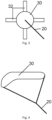
- FIG. 3 and Fig. 4 Two different exemplary underwater floating bodies 30 are shown to illustrate drifting caused by the hydrodynamic element using selected examples. Both examples are shown in the front view, so that drifting to starboard can be seen from the direction of the connecting element 20.
- a first exemplary underwater floating body 30 is shown.
- the underwater floating body 30 has a cruise rudder 32 as a hydrodynamic element.
- the advantage is that the drifting can be specifically adjusted with the cruise rudder 32, for example the drifting to port or, as here, to starboard can be specifically adjusted, for example selected according to the position of the gun barrel from which the ejection occurred.
- the cruise rudder can also prevent twisting if all four rudder blades of the cruise rudder 32 are controlled in a suitable manner.
- Fig.4 shows, however, a purely static hydrodynamic element, which is formed by the shape of the underwater floating body 30 in interaction with the connecting element 20.
- the underwater floating body 30 therefore behaves like a kite in the air and always drifts to starboard when traveling.
Landscapes
- Engineering & Computer Science (AREA)
- General Engineering & Computer Science (AREA)
- Chemical & Material Sciences (AREA)
- Combustion & Propulsion (AREA)
- Ocean & Marine Engineering (AREA)
- Laying Of Electric Cables Or Lines Outside (AREA)
- Electric Cable Installation (AREA)
Applications Claiming Priority (1)
| Application Number | Priority Date | Filing Date | Title |
|---|---|---|---|
| DE102023103889.3A DE102023103889B3 (de) | 2023-02-16 | 2023-02-16 | Sichere Führung eines Kabels an einem Unterseeboot |
Publications (3)
| Publication Number | Publication Date |
|---|---|
| EP4417932A1 true EP4417932A1 (fr) | 2024-08-21 |
| EP4417932C0 EP4417932C0 (fr) | 2026-01-14 |
| EP4417932B1 EP4417932B1 (fr) | 2026-01-14 |
Family
ID=89897562
Family Applications (1)
| Application Number | Title | Priority Date | Filing Date |
|---|---|---|---|
| EP24156600.9A Active EP4417932B1 (fr) | 2023-02-16 | 2024-02-08 | Guidage sécurisé d'un câble sur un sous-marin |
Country Status (2)
| Country | Link |
|---|---|
| EP (1) | EP4417932B1 (fr) |
| DE (1) | DE102023103889B3 (fr) |
Citations (9)
| Publication number | Priority date | Publication date | Assignee | Title |
|---|---|---|---|---|
| DE977844C (de) * | 1963-06-30 | 1971-09-02 | Licentia Gmbh | Einrichtung zum Abspreizen eines aus einem Torpedorohr austretenden, flexiblen Schutzrohres fuer den Steuerdraht eines drahtgesteuerten Torpedos |
| FR2654204A1 (fr) | 1989-11-09 | 1991-05-10 | France Etat Armement | Dispositif de deroulement de cable de filotransmission d'un engin se deplacant a grande vitesse dans un fluide. |
| EP0504049A1 (fr) * | 1991-03-14 | 1992-09-16 | ETAT FRANCAIS Représenté par le délégué général pour l'armement | Procédé et dispositif de déploiement d'un câble de filotransmission d'un engin sous-marin à partir d'une plate-forme de lancement |
| DE3818840C1 (de) | 1988-06-03 | 1994-01-20 | Deutsche Aerospace | Einrichtung zur Zugkraftentlastung von Lichtwellenleiter |
| DE4440150C2 (de) | 1994-11-10 | 1997-05-15 | Bundesrep Deutschland | Aufklärungsfahrzeug für Uboote |
| US20050224614A1 (en) | 2002-06-12 | 2005-10-13 | Dcn | Device for unwinding a wire providing data transmission of any type between two mobile elements operating in a fluid |
| DE202004021039U1 (de) | 2004-07-15 | 2006-12-21 | Lfk-Lenkflugkörpersysteme Gmbh | Hydrodynamische Einrichtung an einem Spulenaufschwimmkörper |
| DE102007053103B3 (de) | 2007-11-07 | 2009-04-09 | Atlas Elektronik Gmbh | Verfahren zur Aufklärung eines Seegebiets |
| DE102009053742A1 (de) * | 2009-11-18 | 2011-05-19 | Atlas Elektronik Gmbh | Unbemanntes Unterwasserfahrzeug und Einrichtung zum Anschluss eines Lichtwellenleiterkabels an ein unbemanntes Unterwasserfahrzeug |
-
2023
- 2023-02-16 DE DE102023103889.3A patent/DE102023103889B3/de active Active
-
2024
- 2024-02-08 EP EP24156600.9A patent/EP4417932B1/fr active Active
Patent Citations (11)
| Publication number | Priority date | Publication date | Assignee | Title |
|---|---|---|---|---|
| DE977844C (de) * | 1963-06-30 | 1971-09-02 | Licentia Gmbh | Einrichtung zum Abspreizen eines aus einem Torpedorohr austretenden, flexiblen Schutzrohres fuer den Steuerdraht eines drahtgesteuerten Torpedos |
| DE3818840C1 (de) | 1988-06-03 | 1994-01-20 | Deutsche Aerospace | Einrichtung zur Zugkraftentlastung von Lichtwellenleiter |
| FR2654204A1 (fr) | 1989-11-09 | 1991-05-10 | France Etat Armement | Dispositif de deroulement de cable de filotransmission d'un engin se deplacant a grande vitesse dans un fluide. |
| EP0504049A1 (fr) * | 1991-03-14 | 1992-09-16 | ETAT FRANCAIS Représenté par le délégué général pour l'armement | Procédé et dispositif de déploiement d'un câble de filotransmission d'un engin sous-marin à partir d'une plate-forme de lancement |
| DE69203011T2 (de) | 1991-03-14 | 1996-01-25 | France Etat | Verfahren und Vorrichtung zum Entfalten eines Faserübertragungskabels für ein Gerät aus einer Unterwasserstartrampe. |
| DE4440150C2 (de) | 1994-11-10 | 1997-05-15 | Bundesrep Deutschland | Aufklärungsfahrzeug für Uboote |
| US20050224614A1 (en) | 2002-06-12 | 2005-10-13 | Dcn | Device for unwinding a wire providing data transmission of any type between two mobile elements operating in a fluid |
| US7156042B2 (en) * | 2002-06-12 | 2007-01-02 | Dcn | Device for unwinding a wire providing data transmission of any type between two mobile elements operating in a fluid |
| DE202004021039U1 (de) | 2004-07-15 | 2006-12-21 | Lfk-Lenkflugkörpersysteme Gmbh | Hydrodynamische Einrichtung an einem Spulenaufschwimmkörper |
| DE102007053103B3 (de) | 2007-11-07 | 2009-04-09 | Atlas Elektronik Gmbh | Verfahren zur Aufklärung eines Seegebiets |
| DE102009053742A1 (de) * | 2009-11-18 | 2011-05-19 | Atlas Elektronik Gmbh | Unbemanntes Unterwasserfahrzeug und Einrichtung zum Anschluss eines Lichtwellenleiterkabels an ein unbemanntes Unterwasserfahrzeug |
Also Published As
| Publication number | Publication date |
|---|---|
| EP4417932C0 (fr) | 2026-01-14 |
| EP4417932B1 (fr) | 2026-01-14 |
| DE102023103889B3 (de) | 2024-04-18 |
Similar Documents
| Publication | Publication Date | Title |
|---|---|---|
| EP2054295B1 (fr) | Dispositif de demarrage et de recuperation pour element profile aerodynamique et element profile aerodynamique | |
| DE69906646T2 (de) | Vorrichtung zur Treibstoffaufnahme während des Fluges eines Flugzeuges mit verschiebbarer Sonde | |
| DE2245791C3 (de) | Unterwasserfahrzeug | |
| DE60019304T2 (de) | Schlepper | |
| DE102004018814A1 (de) | Setzsystem für ein ausfliegendes drachenartiges Windangriffselement bei einem Wasserfahrzeug mit Windantrieb | |
| DE2831472C2 (fr) | ||
| DE3437824A1 (de) | Unbemannter flugkoerper mit einem fallschirmbergesystem | |
| EP3652062A1 (fr) | Corps sous-marin à volume modulable et procédé permettant de faire fonctionner un tel corps sous-marin | |
| DE10023016B4 (de) | Luftfahrzeug sowie Antriebssystem und Steuerungsverfahren | |
| DE69203011T2 (de) | Verfahren und Vorrichtung zum Entfalten eines Faserübertragungskabels für ein Gerät aus einer Unterwasserstartrampe. | |
| EP1507311B1 (fr) | Dispositif de largage pour une antenne remarquée ou une cable remarqée | |
| EP4298016B1 (fr) | Véhicule aérien avec mécanisme d'ailes repliables | |
| DE102023103889B3 (de) | Sichere Führung eines Kabels an einem Unterseeboot | |
| EP0124133A2 (fr) | Dispositif d'emmagasinage d'antennes traînantes pour sous-marins | |
| DE102019206795B4 (de) | Unterwasserfahrzeug | |
| DE69601799T2 (de) | Geschleppter akustischer sender | |
| EP4444615B1 (fr) | Dispositif et procédé pour recevoir de l'eau dans un aéronef en vol | |
| WO2011095178A1 (fr) | Navire à corps profilé disposé en proue | |
| DE102017004420A1 (de) | Verfahren zum Betrieb eines unbemannten, kabelgebundenen Starrflüglers | |
| DE102004024858A1 (de) | Verfahren zur Steuerung eines Lenkflugkörpers, Lenkflugkörper und Datenleitungsbehälter | |
| DE102016006746A1 (de) | Antriebseinrichtung für ein Wasserfahrzeug sowie Wasserfahrzeug | |
| DE102019203090A1 (de) | Wasserfahrzeug mit einem Schleppsonar | |
| DE19940396A1 (de) | Verfahren zum Zuwasserlassen, zum Schleppen und zur Bergung eines drahtgelenkten Untersee-Geräts und Vorrichtung zur Umsetzung dieses Verfahrens | |
| EP3995391B1 (fr) | Embarcation et procédé | |
| DE102019128097B4 (de) | Steuervorrichtung für eine Drohne |
Legal Events
| Date | Code | Title | Description |
|---|---|---|---|
| PUAI | Public reference made under article 153(3) epc to a published international application that has entered the european phase |
Free format text: ORIGINAL CODE: 0009012 |
|
| STAA | Information on the status of an ep patent application or granted ep patent |
Free format text: STATUS: THE APPLICATION HAS BEEN PUBLISHED |
|
| AK | Designated contracting states |
Kind code of ref document: A1 Designated state(s): AL AT BE BG CH CY CZ DE DK EE ES FI FR GB GR HR HU IE IS IT LI LT LU LV MC ME MK MT NL NO PL PT RO RS SE SI SK SM TR |
|
| STAA | Information on the status of an ep patent application or granted ep patent |
Free format text: STATUS: REQUEST FOR EXAMINATION WAS MADE |
|
| 17P | Request for examination filed |
Effective date: 20250221 |
|
| GRAP | Despatch of communication of intention to grant a patent |
Free format text: ORIGINAL CODE: EPIDOSNIGR1 |
|
| STAA | Information on the status of an ep patent application or granted ep patent |
Free format text: STATUS: GRANT OF PATENT IS INTENDED |
|
| RIC1 | Information provided on ipc code assigned before grant |
Ipc: F41F 3/10 20060101AFI20250710BHEP Ipc: F41G 7/32 20060101ALI20250710BHEP |
|
| INTG | Intention to grant announced |
Effective date: 20250731 |
|
| RAP3 | Party data changed (applicant data changed or rights of an application transferred) |
Owner name: TKMS GMBH Owner name: THYSSENKRUPP AG |
|
| GRAS | Grant fee paid |
Free format text: ORIGINAL CODE: EPIDOSNIGR3 |
|
| GRAA | (expected) grant |
Free format text: ORIGINAL CODE: 0009210 |
|
| STAA | Information on the status of an ep patent application or granted ep patent |
Free format text: STATUS: THE PATENT HAS BEEN GRANTED |
|
| AK | Designated contracting states |
Kind code of ref document: B1 Designated state(s): AL AT BE BG CH CY CZ DE DK EE ES FI FR GB GR HR HU IE IS IT LI LT LU LV MC ME MK MT NL NO PL PT RO RS SE SI SK SM TR |
|
| REG | Reference to a national code |
Ref country code: CH Ref legal event code: F10 Free format text: ST27 STATUS EVENT CODE: U-0-0-F10-F00 (AS PROVIDED BY THE NATIONAL OFFICE) Effective date: 20260114 Ref country code: GB Ref legal event code: FG4D Free format text: NOT ENGLISH |
|
| REG | Reference to a national code |
Ref country code: DE Ref legal event code: R096 Ref document number: 502024000588 Country of ref document: DE |
|
| REG | Reference to a national code |
Ref country code: IE Ref legal event code: FG4D Free format text: LANGUAGE OF EP DOCUMENT: GERMAN |
|
| U01 | Request for unitary effect filed |
Effective date: 20260204 |
|
| U07 | Unitary effect registered |
Designated state(s): AT BE BG DE DK EE FI FR IT LT LU LV MT NL PT RO SE SI Effective date: 20260210 |
|
| PGFP | Annual fee paid to national office [announced via postgrant information from national office to epo] |
Ref country code: NO Payment date: 20260220 Year of fee payment: 3 |
|
| PGFP | Annual fee paid to national office [announced via postgrant information from national office to epo] |
Ref country code: AT Payment date: 20260301 Year of fee payment: 3 |
|
| U20 | Renewal fee for the european patent with unitary effect paid |
Year of fee payment: 3 Effective date: 20260326 |