EP4418005A1 - Procédé et circuit pour déterminer la distance d'un objet à partir d'un dispositif de mesure optique de temps de vol et utilisation de ce procédé et dudit circuit pour un dispositif lidar - Google Patents
Procédé et circuit pour déterminer la distance d'un objet à partir d'un dispositif de mesure optique de temps de vol et utilisation de ce procédé et dudit circuit pour un dispositif lidar Download PDFInfo
- Publication number
- EP4418005A1 EP4418005A1 EP24157676.8A EP24157676A EP4418005A1 EP 4418005 A1 EP4418005 A1 EP 4418005A1 EP 24157676 A EP24157676 A EP 24157676A EP 4418005 A1 EP4418005 A1 EP 4418005A1
- Authority
- EP
- European Patent Office
- Prior art keywords
- input
- time interval
- event
- detection radiation
- imax
- Prior art date
- Legal status (The legal status is an assumption and is not a legal conclusion. Google has not performed a legal analysis and makes no representation as to the accuracy of the status listed.)
- Pending
Links
Images

Classifications
-
- G—PHYSICS
- G01—MEASURING; TESTING
- G01S—RADIO DIRECTION-FINDING; RADIO NAVIGATION; DETERMINING DISTANCE OR VELOCITY BY USE OF RADIO WAVES; LOCATING OR PRESENCE-DETECTING BY USE OF THE REFLECTION OR RERADIATION OF RADIO WAVES; ANALOGOUS ARRANGEMENTS USING OTHER WAVES
- G01S7/00—Details of systems according to groups G01S13/00, G01S15/00, G01S17/00
- G01S7/48—Details of systems according to groups G01S13/00, G01S15/00, G01S17/00 of systems according to group G01S17/00
- G01S7/483—Details of pulse systems
- G01S7/486—Receivers
- G01S7/4865—Time delay measurement, e.g. time-of-flight measurement, time of arrival measurement or determining the exact position of a peak
-
- G—PHYSICS
- G01—MEASURING; TESTING
- G01S—RADIO DIRECTION-FINDING; RADIO NAVIGATION; DETERMINING DISTANCE OR VELOCITY BY USE OF RADIO WAVES; LOCATING OR PRESENCE-DETECTING BY USE OF THE REFLECTION OR RERADIATION OF RADIO WAVES; ANALOGOUS ARRANGEMENTS USING OTHER WAVES
- G01S17/00—Systems using the reflection or reradiation of electromagnetic waves other than radio waves, e.g. lidar systems
- G01S17/88—Lidar systems specially adapted for specific applications
- G01S17/93—Lidar systems specially adapted for specific applications for anti-collision purposes
- G01S17/931—Lidar systems specially adapted for specific applications for anti-collision purposes of land vehicles
Definitions
- the invention relates to a method for determining the distance of an object from an optical ToF measuring device by evaluating a distance recording of the object obtained by means of the ToF measuring device, wherein the ToF measuring device has a pulsed transmitting unit for detection radiation, a photodiode array having photodiodes for receiving detection radiation reflected from an object and a signal processing unit.
- the invention relates to an optimal interpolation filter for evaluating histograms and in particular to a method for interpolation or extrapolation between adjacent classes of a histogram.
- the invention also relates to a device for carrying out the aforementioned methods as well as the application of these methods and the device for determining the distance of an object from an optical ToF measuring device.
- the invention also relates to the use of the aforementioned methods and devices for a LIDAR device, in particular of a vehicle.
- a histogram describes the frequency distribution of cardinally scaled features, with the data being divided into classes (BINS) that can have a constant or variable width. If a more detailed investigation is to be carried out, interpolation or extrapolation between neighboring classes may be necessary.
- BINS classes
- the object of the invention is therefore to provide a simplified method for determining the statistically most probable result of a defined event of a process, e.g. the statically most probable time for the occurrence of a defined event of a process.
- This method can be used in particular for determining the distance of an object from an optical ToF measuring device.
- a LIDAR system for the distance measurement in this application according to the invention, for example, a LIDAR system can be used, as is exemplified in WO-A-2021/140160
- a pulsed transmission unit for preferably invisible detection radiation sends detection radiation pulses into an observation area in which an object is potentially located. Detection radiation reflected from the observation area is received by means of a photodiode array as a receiving unit.
- the procedure is such that the rows or columns of the typically two-dimensional photodiode array are sequentially exposed, ie activated, and pulsed several times within a measurement interval (up to to 1000 times). After each detection radiation pulse, each exposed photodiode is examined to determine whether it has generated an amount of electrical charge that exceeds a noise threshold.
- the reference time can be, for example, the start of the respective detection radiation pulse.
- the time at which the photodiode in question generated the amount of electrical charge is therefore determined.
- This time is then assigned to one of several time intervals, i.e. one of several classes or bins, and registered accordingly as an event.
- the statistical evaluation of the measurement results can be carried out by examining which class (which time interval) has the largest number of events (hereinafter referred to as maximum event time interval).
- the index Imax of this time interval (class or bin) is registered and the time T Imax is determined in relation to the reference time that is assigned to the center of the maximum event time interval.
- This point in time which has been determined on the basis of an interpolation or extrapolation, represents the propagation speed of the detection radiation as well as the reference point in time (for example, the beginning of the detection radiation pulse) and the Relative arrangement of the transmitter unit or its detection radiation source and photodiode array in relation to their distances from the object the distance of the ToF measuring device from the detection radiation reflection point of the object from which the relevant photodiode has received detection radiation.
- the distance is equal to half the time difference between the reference time (start of the detection radiation pulse) and the calculated, statistically most probable reception time T A multiplied by the propagation speed of the detection radiation. In simple terms, this gives the distance of the object from the ToF measuring device, which typically combines both the transmitter unit and the receiver unit (photodiode array) in one device.
- the "distance recording" of the object can be created.
- the time period within which the reception of reflected radiation is expected from the reference time (this time period is calculated, for example, based on the propagation speed of the detection radiation and the maximum detectable distance of the object from the ToF measuring device) is divided into individual adjacent and consecutive time intervals (classes). Each time interval is characterized by an index that, starting from the reference time, represents the time corresponding to the center of the time interval.
- the time intervals can be of the same or different lengths (or, more generally, the classes can include value ranges of the same or different sizes).
- the index 1 for the first time interval represents the time 5 ms and the index 2 of the second time interval represents the time 15 ms after the reference time.
- the statistically most probable point in time calculated according to the invention is therefore an interpolated new index which is to be converted into the point in time corresponding to this position based on its position on the time axis.
- the amount of data that has to be processed according to the invention is very high. Therefore, hardware is required that can process this large amount of data, preferably in real time. This is achieved because the method according to the invention only requires a small amount of computing power for the mathematical operations and this small amount of computing power can also be carried out with high performance, so that these large amounts of data can be processed in the shortest possible time.
- the statistically most probable time T A is calculated within the maximum event time interval and the next time interval before and after this, to which the larger number of events is assigned.
- the class in which the largest number of results fall is determined based on the statistically analyzed results of a process event, which are assigned to individual classes of the histogram and registered for these classes. For the subsequent calculation, only the order number, i.e. the index of the class or bin, is required.
- the calculation requires the numbers of events that have been assigned to four further classes, namely the two classes with the next smallest and second smallest indices compared to the maximum event class and with the next highest and second smallest indices compared to the maximum event class.
- the difference between the number of events in the two classes with the next smallest and next largest indices compared to the index of the maximum event class is calculated and then this difference is multiplied by the coefficient k 1 . Furthermore, the difference between the number of events in the two classes with the second smallest and second largest indices compared to the maximum event class is calculated and this difference is multiplied by the coefficient k 2 .
- the value ranges or concrete values for the coefficients k 0 , k 1 and k 2 arise from empirical studies and theoretical considerations.
- the coefficients k 1 and k 2 are preferably the reciprocals of powers of 2.
- the coefficient k 1 can lie between the reciprocal of 2 9 and 2 5 or between 1/256 and 1/64 or between 1/192 and 1/96 and in particular be equal to 1/128, i.e. equal to the reciprocal of 2 7 .
- the coefficient k 2 can lie between the reciprocal of 2 13 and 2 9 or between 1/4096 and 1/1024 or between 1/3072 and 1/1536 and in particular be equal to 1/2048, i.e. equal to the reciprocal of 2 11 .
- the calculation can be implemented very easily as hardware in semiconductor material. All operations are based on shift operations, which means that the calculation can be carried out very quickly.
- the invention further proposes the use of the methods and circuits for a LIDAR device, in particular of a vehicle, wherein the LIDAR device is provided with the transmitting unit for pulsed detection radiation and the one- or two-dimensional photodiode array and a transmitting optics assigned to the transmitting unit for the detection radiation pulses as well as a receiving optics assigned to the photodiode array for detection radiation pulses reflected from an object and with the signal processing unit, When using the circuit, it is part of the signal processing unit.
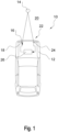
- Fig.1 shows schematically the main components of a device 10 for determining the distance of a vehicle 12 from an object 14.
- the device 10 has a transmitting unit 16 with a detection radiation source 18, which emits individual detection radiation pulses (in this embodiment into the area 20 in front of the vehicle 12). After reflection from an object 14 potentially located in the area 20, the reflected detection radiation reaches a receiving unit 22, which has a photodiode array 24 with a large number of one- or two-dimensionally arranged photodiodes.
- a signal processing unit 26 with a computer unit, memories, analog/digital converters and I/O interfaces controls the transmitting unit 16 on the one hand and evaluates the signals coming from the receiving unit 22 on the other.
- the measurement is carried out within several consecutive measuring intervals.
- the detection radiation source 18 emits up to 1000 detection radiation pulses per measuring interval.
- the receiving unit 22 detects up to up to 1000 events, namely up to 1000 times the generation of electrical charge by the photodiodes. Different photodiodes of the photodiode array are activated for each measurement interval.
- FIG. 2 A typical example of the frequency distribution of the results occurring in a measurement interval, ie the distribution of the number of results over time, is shown in Fig. 2 shown.
- the index or bin is plotted on the X-axis.
- Each index represents a time interval within which the active photodiodes have generated electrical charge after the emission of a detection radiation pulse.
- the number of events i.e. the number of times electrical charge is generated by more than a threshold value, is shown on the Y-axis.
- Each index represents the center point of a time interval.
- the statistically most probable time for receiving the detection reflection radiation is the index of the time interval in which most events occur. Rather, however, this statistically most probable reception time is obtained by interpolating or extrapolating the events that are distributed across several indices. According to the invention, the index with the largest number of events is determined. Furthermore, the numbers of events that fall into the two next smaller and the two next larger indices (time intervals) are determined.
- T A N + 1 ⁇ N ⁇ 1 ⁇ k 1 + N + 2 ⁇ N ⁇ 2 ⁇ k 2 + T Imax ⁇ k 0
- Imax is the maximum event time interval
- N +1 is the number of events in the next largest time interval
- N +2 is the number of events in the second smallest time interval
- N -1 is the number of events in the next smallest time interval
- N -2 is the number of events in the second smallest time interval
- k 0 1
- k 1 is 1/128
- k 2 is 1/2048.
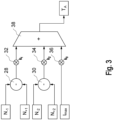
- FIG.3 A possible hardware implementation for calculating the above formula is described in Fig.3 shown.
- the difference between the numbers N -1 and N +1 is calculated in a first subtraction unit 28, while the difference between N -2 and N +2 is determined in a second subtraction unit 30.
- the result provided by the subtraction unit 28 is multiplied by the coefficient k 1 in the first multiplication unit 32, while the result of the second subtraction unit 30 is multiplied by the coefficient k 2 in a second multiplication unit 34.
- the index Imax is multiplied by the coefficient k 0 in a third multiplication unit 36.
- the three product results are added in an addition unit 38 and result in a new index which represents the statistically most probable reception time T A calculated by interpolation or extrapolation for the detection radiation received by the respectively activated photodiodes from a reflection point of the object.
Landscapes
- Engineering & Computer Science (AREA)
- Physics & Mathematics (AREA)
- Computer Networks & Wireless Communication (AREA)
- General Physics & Mathematics (AREA)
- Radar, Positioning & Navigation (AREA)
- Remote Sensing (AREA)
- Electromagnetism (AREA)
- Radar Systems Or Details Thereof (AREA)
Applications Claiming Priority (1)
| Application Number | Priority Date | Filing Date | Title |
|---|---|---|---|
| EP23156988 | 2023-02-16 |
Publications (1)
| Publication Number | Publication Date |
|---|---|
| EP4418005A1 true EP4418005A1 (fr) | 2024-08-21 |
Family
ID=85277977
Family Applications (1)
| Application Number | Title | Priority Date | Filing Date |
|---|---|---|---|
| EP24157676.8A Pending EP4418005A1 (fr) | 2023-02-16 | 2024-02-14 | Procédé et circuit pour déterminer la distance d'un objet à partir d'un dispositif de mesure optique de temps de vol et utilisation de ce procédé et dudit circuit pour un dispositif lidar |
Country Status (1)
| Country | Link |
|---|---|
| EP (1) | EP4418005A1 (fr) |
Citations (3)
| Publication number | Priority date | Publication date | Assignee | Title |
|---|---|---|---|---|
| US20190056497A1 (en) | 2017-03-01 | 2019-02-21 | Ouster, Inc. | Accurate photo detector measurements for lidar |
| WO2021026241A1 (fr) | 2019-08-05 | 2021-02-11 | Ouster, Inc. | Système de traitement pour mesures lidar |
| WO2021140160A1 (fr) | 2020-01-07 | 2021-07-15 | Elmos Semiconductor Se | Module lumineux et appareil lidar possédant au moins un module lumineux de ce type |
-
2024
- 2024-02-14 EP EP24157676.8A patent/EP4418005A1/fr active Pending
Patent Citations (3)
| Publication number | Priority date | Publication date | Assignee | Title |
|---|---|---|---|---|
| US20190056497A1 (en) | 2017-03-01 | 2019-02-21 | Ouster, Inc. | Accurate photo detector measurements for lidar |
| WO2021026241A1 (fr) | 2019-08-05 | 2021-02-11 | Ouster, Inc. | Système de traitement pour mesures lidar |
| WO2021140160A1 (fr) | 2020-01-07 | 2021-07-15 | Elmos Semiconductor Se | Module lumineux et appareil lidar possédant au moins un module lumineux de ce type |
Similar Documents
| Publication | Publication Date | Title |
|---|---|---|
| EP3683599B1 (fr) | Procédé et dispositif de mesure de distance optique | |
| DE4133196C2 (de) | Entfernungsmessvorrichtung | |
| EP3161517B1 (fr) | Procédé de localisation d'objets au moyen d'un radar fmcw | |
| EP0748454B1 (fr) | Procede permettant de determiner de maniere ultrasonore la position d'un objet par rapport a un arriere-plan | |
| EP0269902B1 (fr) | Procédé et dispositif pour mesurer la distance entre deux objets, en particulier entre deux véhicules à moteur | |
| EP0742450A2 (fr) | Procédé et dispositif de mesure du temps de vol de lumière le long d'une trajectoire de mesure entre un dispositif de mesure et un objet réfléchissant | |
| EP0573034A2 (fr) | Méthode et appareil de télémétrie au moyen de mesure de temps de parcours d'impulsions | |
| DE102018130022B4 (de) | Verfahren zur Bestimmung einer Ankunftszeit eines eine physikalische Messgröße repräsentierenden, digitalisierten Signalpulses, Auswerteeinheit, Vorrichtung, Auswertsystem und Strahlendetektionssystem | |
| EP3435114A1 (fr) | Procédé de transmission de données représentant des signaux de mesure par ultrasons, en particulier dans un véhicule | |
| EP3599485B1 (fr) | Procédé et dispositif de mesure de distance optique | |
| DE69818380T2 (de) | Verfahren zur Überwachung eines mit Beschleunigungssensoren versehenen Planetengetriebes in einem Fortbewegungsmittel, insbesondere in einem Helikopter | |
| DE102004035715B4 (de) | Schalllaufzeitmessvorrichtung | |
| DE102017220774A1 (de) | Vorrichtung und Verfahren zum Bestimmen einer Distanz zu einem Objekt | |
| EP4418005A1 (fr) | Procédé et circuit pour déterminer la distance d'un objet à partir d'un dispositif de mesure optique de temps de vol et utilisation de ce procédé et dudit circuit pour un dispositif lidar | |
| DE102018201735B4 (de) | Vorrichtung und Verfahren zum Ermitteln eines Abstandes eines bewegten Objekts | |
| EP0777130A2 (fr) | Procédé digital de détection d'impulsions courtes et appareil pour la mise en oeuvre du procédé | |
| DE69906640T2 (de) | Verfahren zur Wiederherstellung der Radarempfindlichkeit bei gepulster elektromagnetischer Störung | |
| DE102018221285A1 (de) | Verfahren zur Interferenzunterdrückung und Verfahren zur Signalwiederherstellung | |
| DE69131194T2 (de) | Unterdrückung des Überfaltungsartefaktes in Puls-Dopplersystemen | |
| EP3938804B1 (fr) | Dispositif de balayage laser et procédé de mesure tridimensionnelle d'une scène à une distance élevée | |
| WO2002063247A2 (fr) | Procede et dispositif de detection grossiere d'une matiere de remplissage dans un recipient dans du liquide ou une matiere deversable | |
| WO2002071016A1 (fr) | Procede de comptage de photons dans des systemes de balayage laser | |
| DE19616594A1 (de) | Vorrichtung und Verfahren zum Testen einer optischen Strecke | |
| DE102023119216B3 (de) | FMCW-Verfahren | |
| EP4411325B1 (fr) | Procédé de fonctionnement d'un débitmètre à induction magnétique et débitmètre à induction magnétique correspondant |
Legal Events
| Date | Code | Title | Description |
|---|---|---|---|
| PUAI | Public reference made under article 153(3) epc to a published international application that has entered the european phase |
Free format text: ORIGINAL CODE: 0009012 |
|
| STAA | Information on the status of an ep patent application or granted ep patent |
Free format text: STATUS: THE APPLICATION HAS BEEN PUBLISHED |
|
| AK | Designated contracting states |
Kind code of ref document: A1 Designated state(s): AL AT BE BG CH CY CZ DE DK EE ES FI FR GB GR HR HU IE IS IT LI LT LU LV MC ME MK MT NL NO PL PT RO RS SE SI SK SM TR |
|
| STAA | Information on the status of an ep patent application or granted ep patent |
Free format text: STATUS: REQUEST FOR EXAMINATION WAS MADE |
|
| 17P | Request for examination filed |
Effective date: 20241118 |
|
| RBV | Designated contracting states (corrected) |
Designated state(s): AL AT BE BG CH CY CZ DE DK EE ES FI FR GB GR HR HU IE IS IT LI LT LU LV MC ME MK MT NL NO PL PT RO RS SE SI SK SM TR |
|
| RAP3 | Party data changed (applicant data changed or rights of an application transferred) |
Owner name: ELMOS SEMICONDUCTOR SE |