EP4418432A1 - Cellule de batterie, batterie et dispositif électrique - Google Patents
Cellule de batterie, batterie et dispositif électrique Download PDFInfo
- Publication number
- EP4418432A1 EP4418432A1 EP22928110.0A EP22928110A EP4418432A1 EP 4418432 A1 EP4418432 A1 EP 4418432A1 EP 22928110 A EP22928110 A EP 22928110A EP 4418432 A1 EP4418432 A1 EP 4418432A1
- Authority
- EP
- European Patent Office
- Prior art keywords
- battery cell
- pressure relief
- hole segment
- relief mechanism
- wall
- Prior art date
- Legal status (The legal status is an assumption and is not a legal conclusion. Google has not performed a legal analysis and makes no representation as to the accuracy of the status listed.)
- Pending
Links
Images


Classifications
-
- H—ELECTRICITY
- H01—ELECTRIC ELEMENTS
- H01M—PROCESSES OR MEANS, e.g. BATTERIES, FOR THE DIRECT CONVERSION OF CHEMICAL ENERGY INTO ELECTRICAL ENERGY
- H01M50/00—Constructional details or processes of manufacture of the non-active parts of electrochemical cells other than fuel cells, e.g. hybrid cells
- H01M50/10—Primary casings; Jackets or wrappings
- H01M50/102—Primary casings; Jackets or wrappings characterised by their shape or physical structure
- H01M50/103—Primary casings; Jackets or wrappings characterised by their shape or physical structure prismatic or rectangular
-
- H—ELECTRICITY
- H01—ELECTRIC ELEMENTS
- H01M—PROCESSES OR MEANS, e.g. BATTERIES, FOR THE DIRECT CONVERSION OF CHEMICAL ENERGY INTO ELECTRICAL ENERGY
- H01M10/00—Secondary cells; Manufacture thereof
- H01M10/60—Heating or cooling; Temperature control
- H01M10/61—Types of temperature control
- H01M10/613—Cooling or keeping cold
-
- H—ELECTRICITY
- H01—ELECTRIC ELEMENTS
- H01M—PROCESSES OR MEANS, e.g. BATTERIES, FOR THE DIRECT CONVERSION OF CHEMICAL ENERGY INTO ELECTRICAL ENERGY
- H01M10/00—Secondary cells; Manufacture thereof
- H01M10/60—Heating or cooling; Temperature control
- H01M10/65—Means for temperature control structurally associated with the cells
- H01M10/655—Solid structures for heat exchange or heat conduction
- H01M10/6554—Rods or plates
-
- H—ELECTRICITY
- H01—ELECTRIC ELEMENTS
- H01M—PROCESSES OR MEANS, e.g. BATTERIES, FOR THE DIRECT CONVERSION OF CHEMICAL ENERGY INTO ELECTRICAL ENERGY
- H01M50/00—Constructional details or processes of manufacture of the non-active parts of electrochemical cells other than fuel cells, e.g. hybrid cells
- H01M50/10—Primary casings; Jackets or wrappings
- H01M50/131—Primary casings; Jackets or wrappings characterised by physical properties, e.g. gas permeability, size or heat resistance
-
- H—ELECTRICITY
- H01—ELECTRIC ELEMENTS
- H01M—PROCESSES OR MEANS, e.g. BATTERIES, FOR THE DIRECT CONVERSION OF CHEMICAL ENERGY INTO ELECTRICAL ENERGY
- H01M50/00—Constructional details or processes of manufacture of the non-active parts of electrochemical cells other than fuel cells, e.g. hybrid cells
- H01M50/10—Primary casings; Jackets or wrappings
- H01M50/147—Lids or covers
- H01M50/148—Lids or covers characterised by their shape
- H01M50/15—Lids or covers characterised by their shape for prismatic or rectangular cells
-
- H—ELECTRICITY
- H01—ELECTRIC ELEMENTS
- H01M—PROCESSES OR MEANS, e.g. BATTERIES, FOR THE DIRECT CONVERSION OF CHEMICAL ENERGY INTO ELECTRICAL ENERGY
- H01M50/00—Constructional details or processes of manufacture of the non-active parts of electrochemical cells other than fuel cells, e.g. hybrid cells
- H01M50/20—Mountings; Secondary casings or frames; Racks, modules or packs; Suspension devices; Shock absorbers; Transport or carrying devices; Holders
- H01M50/204—Racks, modules or packs for multiple batteries or multiple cells
- H01M50/207—Racks, modules or packs for multiple batteries or multiple cells characterised by their shape
- H01M50/209—Racks, modules or packs for multiple batteries or multiple cells characterised by their shape adapted for prismatic or rectangular cells
-
- H—ELECTRICITY
- H01—ELECTRIC ELEMENTS
- H01M—PROCESSES OR MEANS, e.g. BATTERIES, FOR THE DIRECT CONVERSION OF CHEMICAL ENERGY INTO ELECTRICAL ENERGY
- H01M50/00—Constructional details or processes of manufacture of the non-active parts of electrochemical cells other than fuel cells, e.g. hybrid cells
- H01M50/20—Mountings; Secondary casings or frames; Racks, modules or packs; Suspension devices; Shock absorbers; Transport or carrying devices; Holders
- H01M50/233—Mountings; Secondary casings or frames; Racks, modules or packs; Suspension devices; Shock absorbers; Transport or carrying devices; Holders characterised by physical properties of casings or racks, e.g. dimensions
- H01M50/242—Mountings; Secondary casings or frames; Racks, modules or packs; Suspension devices; Shock absorbers; Transport or carrying devices; Holders characterised by physical properties of casings or racks, e.g. dimensions adapted for protecting batteries against vibrations, collision impact or swelling
-
- H—ELECTRICITY
- H01—ELECTRIC ELEMENTS
- H01M—PROCESSES OR MEANS, e.g. BATTERIES, FOR THE DIRECT CONVERSION OF CHEMICAL ENERGY INTO ELECTRICAL ENERGY
- H01M50/00—Constructional details or processes of manufacture of the non-active parts of electrochemical cells other than fuel cells, e.g. hybrid cells
- H01M50/20—Mountings; Secondary casings or frames; Racks, modules or packs; Suspension devices; Shock absorbers; Transport or carrying devices; Holders
- H01M50/244—Secondary casings; Racks; Suspension devices; Carrying devices; Holders characterised by their mounting method
-
- H—ELECTRICITY
- H01—ELECTRIC ELEMENTS
- H01M—PROCESSES OR MEANS, e.g. BATTERIES, FOR THE DIRECT CONVERSION OF CHEMICAL ENERGY INTO ELECTRICAL ENERGY
- H01M50/00—Constructional details or processes of manufacture of the non-active parts of electrochemical cells other than fuel cells, e.g. hybrid cells
- H01M50/30—Arrangements for facilitating escape of gases
-
- H—ELECTRICITY
- H01—ELECTRIC ELEMENTS
- H01M—PROCESSES OR MEANS, e.g. BATTERIES, FOR THE DIRECT CONVERSION OF CHEMICAL ENERGY INTO ELECTRICAL ENERGY
- H01M50/00—Constructional details or processes of manufacture of the non-active parts of electrochemical cells other than fuel cells, e.g. hybrid cells
- H01M50/30—Arrangements for facilitating escape of gases
- H01M50/317—Re-sealable arrangements
-
- H—ELECTRICITY
- H01—ELECTRIC ELEMENTS
- H01M—PROCESSES OR MEANS, e.g. BATTERIES, FOR THE DIRECT CONVERSION OF CHEMICAL ENERGY INTO ELECTRICAL ENERGY
- H01M50/00—Constructional details or processes of manufacture of the non-active parts of electrochemical cells other than fuel cells, e.g. hybrid cells
- H01M50/30—Arrangements for facilitating escape of gases
- H01M50/342—Non-re-sealable arrangements
-
- H—ELECTRICITY
- H01—ELECTRIC ELEMENTS
- H01M—PROCESSES OR MEANS, e.g. BATTERIES, FOR THE DIRECT CONVERSION OF CHEMICAL ENERGY INTO ELECTRICAL ENERGY
- H01M50/00—Constructional details or processes of manufacture of the non-active parts of electrochemical cells other than fuel cells, e.g. hybrid cells
- H01M50/30—Arrangements for facilitating escape of gases
- H01M50/342—Non-re-sealable arrangements
- H01M50/3425—Non-re-sealable arrangements in the form of rupturable membranes or weakened parts, e.g. pierced with the aid of a sharp member
-
- H—ELECTRICITY
- H01—ELECTRIC ELEMENTS
- H01M—PROCESSES OR MEANS, e.g. BATTERIES, FOR THE DIRECT CONVERSION OF CHEMICAL ENERGY INTO ELECTRICAL ENERGY
- H01M10/00—Secondary cells; Manufacture thereof
- H01M10/60—Heating or cooling; Temperature control
- H01M10/62—Heating or cooling; Temperature control specially adapted for specific applications
- H01M10/625—Vehicles
-
- H—ELECTRICITY
- H01—ELECTRIC ELEMENTS
- H01M—PROCESSES OR MEANS, e.g. BATTERIES, FOR THE DIRECT CONVERSION OF CHEMICAL ENERGY INTO ELECTRICAL ENERGY
- H01M2200/00—Safety devices for primary or secondary batteries
- H01M2200/20—Pressure-sensitive devices
-
- H—ELECTRICITY
- H01—ELECTRIC ELEMENTS
- H01M—PROCESSES OR MEANS, e.g. BATTERIES, FOR THE DIRECT CONVERSION OF CHEMICAL ENERGY INTO ELECTRICAL ENERGY
- H01M2220/00—Batteries for particular applications
- H01M2220/20—Batteries in motive systems, e.g. vehicle, ship, plane
-
- H—ELECTRICITY
- H01—ELECTRIC ELEMENTS
- H01M—PROCESSES OR MEANS, e.g. BATTERIES, FOR THE DIRECT CONVERSION OF CHEMICAL ENERGY INTO ELECTRICAL ENERGY
- H01M2220/00—Batteries for particular applications
- H01M2220/30—Batteries in portable systems, e.g. mobile phone, laptop
-
- Y—GENERAL TAGGING OF NEW TECHNOLOGICAL DEVELOPMENTS; GENERAL TAGGING OF CROSS-SECTIONAL TECHNOLOGIES SPANNING OVER SEVERAL SECTIONS OF THE IPC; TECHNICAL SUBJECTS COVERED BY FORMER USPC CROSS-REFERENCE ART COLLECTIONS [XRACs] AND DIGESTS
- Y02—TECHNOLOGIES OR APPLICATIONS FOR MITIGATION OR ADAPTATION AGAINST CLIMATE CHANGE
- Y02E—REDUCTION OF GREENHOUSE GAS [GHG] EMISSIONS, RELATED TO ENERGY GENERATION, TRANSMISSION OR DISTRIBUTION
- Y02E60/00—Enabling technologies; Technologies with a potential or indirect contribution to GHG emissions mitigation
- Y02E60/10—Energy storage using batteries
Definitions
- the present application relates to the technical field of batteries, and in particular to a battery cell, a battery and an electricity-consuming apparatus.
- Batteries are widely used in electricity-consuming apparatus, such as mobile phones, laptops, electric vehicles, electric cars, electric planes, electric ships, electric toy cars, electric toy ships, electric toy planes and electric tools.
- Embodiments of the present application provide a battery cell, a battery and an electricity-consuming apparatus, so that the safety performance of the battery cell can be improved.
- a battery cell including a casing and a pressure relief mechanism.
- the casing includes a first wall provided with a through hole; the pressure relief mechanism is arranged on the first wall, and at least a portion of the pressure relief mechanism is located in the through hole.
- the through hole in the first wall of the casing by arranging the through hole in the first wall of the casing and placing at least a portion of the pressure relief mechanism in the through hole, it is beneficial to improving the support force and connecting strength of the casing to the pressure relief mechanism, reducing the risk of affecting the normal operation of the pressure relief mechanism due to the insufficient fixed strength, and improving the safety performance of the battery cell.
- the pressure relief mechanism is completely accommodated in the through hole.
- the through hole includes a first hole segment, a second hole segment and a first connecting face connecting the first hole segment with the second hole segment; a projection area of the first hole segment is smaller than a projection area of the second hole segment in a thickness direction of the first wall, the first hole segment is located at a side of the second hole segment close to an interior of the casing, and an inner wall of the second hole segment is configured to fit with a peripheral side face of the pressure relief mechanism.
- a size T1 of the first hole segment satisfies: T1 ⁇ 0.3mm.
- a size of the first hole segment is T1
- a size of the second hole segment is T2
- T1+T2 ⁇ 3mm T1+T2 ⁇ 3mm.
- the pressure relief mechanism includes a body and a connecting part, the connecting part is arranged around the body and abuts against the first connecting face, the body includes a basal region and a weak region, and a rupture stress of the weak region is smaller than a rupture stress of the basal region.
- the specific size of the rupture stress in the weak region can be set as needed to achieve the opening or rupture of the weak region when the internal pressure of the battery cell reaches the threshold, so as to discharge the gas in the battery cell timely.
- the specific shape of the weak region and the shape of a gas-exhausting channel when the pressure relief mechanism is opened can be set to discharge the gas in the battery cell quickly.
- a projection of the weak region in the thickness direction is located within the first hole segment, and the weak region is spaced apart from an inner wall of the second hole segment in a direction perpendicular to the thickness direction.
- a size of the connecting part is S1
- a width of the first connecting face is D1
- the first direction is a direction passing through a geometric center of the pressure relief mechanism and perpendicular to the thickness direction.
- the through hole further includes a third hole segment and a second connecting face connecting the third hole segment with the second hole segment; in the thickness direction, a projection area of the third hole segment is larger than a projection area of the second hole segment; in the first direction, a width D2 of the second connecting face satisfies: D2 ⁇ 0.5mm, and the first direction is a direction passing through a geometric center of the pressure relief mechanism and perpendicular to the thickness direction.
- a sufficient space for the pressure relief and the welding mark after the first wall welded can be reserved. It is beneficial to ensuring the normal welding operation of the pressure relief mechanism.
- D2 ⁇ 1.2mm D2 ⁇ 1.2mm.
- the battery cell further includes a protective member, the protective member is connected to the first wall and arranged at a side of the pressure relief mechanism close to an exterior of the casing, and in the thickness direction, the minimum distance h between the protective member and the pressure relief mechanism satisfies: h ⁇ 0.2mm.
- the protective member By arranging the protective member, the pressure relief mechanism can be protected to reduce the scratch and other injuries caused by the foreign objects outside the battery cell.
- the minimum distance h between the protective member and the pressure relief mechanism satisfies the above relationship, so that it is beneficial to achieving the normal actuation of the pressure relief mechanism when the pressure in the battery cell reaches the threshold.
- the through hole includes a third hole segment, a fourth hole segment and a third connecting face connecting the third hole segment and the fourth hole segment, the third hole segment is arranged between the second hole segment and the fourth hole segment, and a projection area of the third hole segment is smaller than a projection area of the fourth hole segment in the thickness direction.
- the protective member is connected to the third connecting face, and the maximum size of the protective member is smaller than or equal to a size of the fourth hole segment in the thickness direction.
- a distance h1 between an outer edge of the protective member and an inner wall of the third hole segment satisfies: h1 ⁇ 0.5mm.
- a distance w between the outer edge of the protective member and the inner wall of the fourth hole segment is 0.2mm ⁇ w ⁇ 3mm, in which the first direction is a direction passing through a geometric center of the pressure relief mechanism and perpendicular to the thickness direction.
- the casing includes a casing body and an end cover, the casing body is provided with an opening, and the end cover is configured to cover the opening.
- the pressure relief mechanism is arranged on the casing body, or the pressure relief mechanism is arranged on the end cover. According to actual needs, the specific position of the pressure relief mechanism can be flexibly arranged, so as to reserve the sufficient space for the integration of other related structures of the battery cell.
- the pressure relief mechanism is arranged on the casing body including the first wall, a second wall and two third walls, the first wall and the second wall are arranged opposite to each other, the two third walls are arranged opposite to each other, and each of the third walls connects the first wall and the second wall.
- the position of the pressure relief mechanism can be arranged reasonably according to the spatial layout of various parts in the battery cell.
- a surface area of the first wall is smaller than a surface area of the third wall.
- a side surface of the battery cell with a larger area such as a surface corresponding to the third wall, can be attached to the third wall, so as to improve the space utilization rate of the interior of the battery and the energy density of the battery.
- the casing body is provided with two openings opposite to each other, two end covers are provided, and the two end covers cover the two openings respectively.
- the assembly process of the battery cell can be more convenient and quick.
- embodiments of the present application provide a battery, including the battery cell according to any one of the embodiments as described above.
- the battery provided by the embodiments of the present application has the same technical effect due to using the battery cell provided by any one of the embodiments as described above, and the technical effect will not be repeated here.
- embodiments of the present application provide an electricity-consuming apparatus, including the battery according to the above embodiments, and the battery is configured to supply an electric power.
- the electricity-consuming apparatus provided by the embodiments of the present application has the same technical effect due to using the battery provided by the embodiments as described above, and the technical effect will not be repeated here.
- the battery cell, the battery and the electricity-consuming apparatus are provided by the present application.
- the terms “mount”, “communicate” and “connect” should be understood in a broad sense, for example, it can be a fixed connection, a detachable connection or an integral connection, it can be a direct connection, or it can be connected indirectly through an intermediary.
- the specific meaning of the above-mentioned terms in the present application can be understood according to specific situations.
- a battery cell may include a lithium-ion secondary battery cell, a lithium-ion primary battery cell, a lithium-sulfur battery cell, a sodium lithium ion battery cell, a sodium ion battery cell, a magnesium ion battery cell and the like, which is not limited in the embodiments of the present application.
- the battery cell can be in a shape of a cylinder, a flatten body, a cuboid or other shapes, which is not limited in the embodiments of the present application.
- the battery cell can be divided into three types in packaging: a cylindrical cell, a cuboid rectangle battery cell and soft pack battery cell, which is not limited in the embodiments of the present application.
- the battery mentioned in the embodiments of the present application refers to a single physical module that includes one or more battery cells to provide higher voltage and capacity.
- the battery mentioned in the present application may include a battery module, a battery pack or the like.
- the battery generally includes a housing for packaging one or more battery cells. The housing can prevent liquid or other foreign objects from affecting charging or discharging of the battery cell.
- the battery cell includes an electrode assembly and an electrolyte, and the electrode assembly includes a positive electrode sheet, a negative electrode sheet and a separator.
- the battery cell mainly relies on the movement of metal ions between the positive electrode sheet and the negative electrode sheet to work.
- the positive electrode sheet includes a positive electrode current collector and a positive electrode active material layer.
- the positive electrode active material layer is applied on a surface of the positive electrode current collector.
- a current collector uncoated with the positive electrode active material layer protrudes from the current collector coated with the positive electrode active material layer.
- the current collectors uncoated with the positive electrode active material layer are stacked as a positive electrode tab.
- the material of the positive electrode current collector may be aluminum, and the positive electrode active material may be lithium cobaltate, lithium iron phosphate, ternary lithium, lithium manganite or the like.
- the negative electrode sheet includes a negative electrode current collector and a negative electrode active material layer.
- the negative electrode active material layer is applied on a surface of the negative electrode current collector.
- a current collector uncoated with the negative electrode active material layer protrudes from the current collector coated with the negative electrode active material layer.
- the current collectors uncoated with the negative electrode active material layer are stacked as a negative electrode tab.
- the material of the negative electrode current collector may be copper, and the negative electrode active material may be carbon, silicon or the like.
- the material of the separator may be PP (polypropylene), PE (polyethylene) or the like.
- the electrode assembly may be a winding-type structure or a stack-type structure, which is not limited in the embodiments of the present application.
- a pressure relief mechanism is generally arranged on a casing body of the battery cell. The gas generated in the battery cell is discharged and the pressure is released through the pressure relief mechanism to ensure the safety of the battery cell.
- the inventors After the inventors discover the issue of low safety in the operation of battery cell, they conduct a systematic analysis and research on the structure and working process of the battery cell. The results show that a casing of the battery cell has no sufficient support force for the pressure relief mechanism. During the operation of the battery cell, the pressure relief mechanism may move and loosen relative to the casing, so that it can affect the normal operation of the pressure relief mechanism. In this way, after the gas pressure in the battery cell reaches the predetermined pressure of the pressure relief mechanism, the pressure relief mechanism of the battery cell fails to be activated yet, or when the pressure inside he battery cell does not reach the predetermined pressure, the pressure relief mechanism has already been activated, so that it may pose a certain safety hazard to the battery cell.
- the inventors have improved the structure of the battery cell.
- the technical solution described in embodiments of the present application is applicable to a battery cell, a battery including the battery cell and an electricity-consuming apparatus using the battery.
- the embodiments of the present application provide the battery cell including a casing and a pressure relief mechanism.
- the casing includes a first wall and the first wall is provided with a through hole.
- the pressure relief mechanism is arranged on the first wall, and at least a portion of the pressure relief mechanism is located in the through hole.
- the through hole is provided in the first wall of the casing and at least a portion of the pressure relief mechanism is placed in the through hole, so that it is beneficial to improving the support force and connecting strength of the casing to the pressure relief mechanism, reducing the risk of affecting the normal operation of the pressure relief mechanism due to the insufficient fixed strength, and improving the safety performance of the battery cell.
- the electricity-consuming apparatus may be a vehicle, a mobile phone, a portable device, a notebook computer, a ship, a spacecraft, an electric toy, an electric tool or the like.
- the vehicle may be a fuel car, a gas car or a new energy car, and the new energy car can be a pure electric car, a hybrid car, a range-extended car or the like;
- the spacecraft may include an airplane, a rocket, a space shuttle, a space ship or the like;
- the electric toy may include a fixed-type or mobile-type electric toy, such as a game player, an electric car toy, an electric ship toy, an electric airplane toy or the like;
- the power tool may include a metal cutting power tool, a grinding power tool, an assembly power tool and a railway power tools, such as an electric drill, an electric grinder, an electric wrench, an electric screwdriver, an electric hammer, an impact drill, a concrete vibrator, an electric planers or the like.
- a battery 10 may be arranged inside the vehicle 1, and the battery 10 may be arranged in the bottom, the front or the back of the vehicle 1.
- the battery 10 can be used to supply power to the vehicle 1, for example, the battery 10 can be used as an operating power source of the vehicle 1.
- the vehicle 1 may further include a controller 1b and a motor 1a.
- the controller 1b can be used to control the battery 10 to supply power to the motor 1a, for example, for satisfying the work electricity needs of the vehicle 1 during starting, navigating and driving.
- the battery 10 can not only serve as an operating power source for the vehicle 1, but also as a driving power source for the vehicle 1, so as to replace or partially replace the fuel or the natural gas and provide the driving power for the vehicle 1.
- the battery 10 includes a battery cell (not shown in Fig. 2 ).
- the battery 10 may further include a housing for accommodating the battery cell.
- the housing is used to accommodate the battery cell, and the housing can be of various structural forms.
- the housing may include a first housing body 11 and a second housing body 12.
- the first housing body 11 and the second housing body 12 cover each other.
- the first housing body 11 and the second housing body 12 jointly define an accommodating space for accommodating the battery cell.
- the second housing body 12 may be a hollow structure having an opening at an end, and the first housing body 11 may be a plate-like structure.
- the first housing body 11 is covered with an opening side of the second housing body 12 to form the housing having the accommodating space.
- each of the first housing body 11 and the second housing body 12 may be a hollow structure having an opening on a side.
- first housing body 11 with the opening is covered with the side of the second housing body 12 with the opening to form the housing having the accommodation space.
- first housing body 11 and the second housing body 12 can be in various shapes, such as a cylinder and a rectangular parallelepiped.
- a sealing member such as a sealant and a sealing ring, may be arranged between the first housing body 11 and the second housing body 12.
- first housing body 11 is covered with the second housing body 12, the first housing body 11 can be called an upper housing cover, and the second housing body 12 can be called a lower housing cover.
- the battery 10 there may be one or more battery cells. If there are a plurality of battery cells, the plurality of battery cells can be connected in series, in parallel or in hybrid.
- the hybrid connection means that the plurality of battery cells are connected in series and parallel in combination.
- the plurality of battery cells can be directly connected in series, in parallel or in hybrid together, and then a whole composed of the plurality of battery cells can be accommodated in the housing.
- the plurality of battery cells can be connected in series, parallel or hybrid to form the battery module 20.
- a plurality of battery modules 20 are connected in series, in parallel or in hybrid to form a whole and are accommodated in the housing.
- Fig. 3 is a structural schematic view of a battery module 20 shown in Fig. 2 .
- the battery module 20 has a plurality of battery cells 30.
- the plurality of battery cells 30 are connected in series, in parallel or in hybrid firstly to form the battery module 20.
- the plurality of battery modules 20 are connected in series, in parallel or in hybrid to form a whole and are accommodated in the housing.
- the plurality of battery cells 30 in the battery module 20 can be electrically connected through a busbar to realize the parallel connection, the series connection or the hybrid connection of the plurality of battery cells 30 in the battery module 20.
- Fig. 4 and Fig. 5 show exploded structural schematic views of different battery cells 30 provided by the embodiments of the present application respectively.
- the battery cell 30 provided by the embodiments of the present application includes a casing 31 and a pressure relief mechanism 34.
- the casing 31 includes a first wall 32, and the first wall 32 is provided with a through hole 32a.
- the pressure relief mechanism 34 is arranged on the first wall 32, and at least a portion of the pressure relief mechanism 34 is located in the through hole 32a.
- the battery cell 30 further includes an electrode assembly 33.
- the casing 31 is provided with an accommodating cavity 31a, and the electrode assembly 33 is accommodated in the accommodating cavity 31a.
- the casing 31 may include a casing body 311 and an end cover 312.
- the casing body 311 is a hollow structure with an opening on a side or openings on a plurality of sides (including two sides).
- the end cover 312 covers the opening 311a of the casing body 311 and forms a sealing connection to form a sealing space for accommodating the electrode assembly 33 and the electrolyte.
- the electrode assembly 33 can be placed into the casing body 311 firstly, then the end cover 312 covers the opening 311a of the casing body 311, and then the electrolyte is injected into the casing body 311 via an electrolyte injection port on the end cover 312.
- the casing 31 may also contain the electrolyte, such as electrolyte solution.
- the casing 31 may have various structural forms.
- the casing body 311 can be in various shapes, such as cylinder and cuboid.
- the shape of the casing body 311 can be determined according to the specific shape of the electrode assembly 33. For example, if the electrode assembly 33 has a cylindrical structure, the casing body 311 can be a cylindrical structure. If the electrode assembly 33 has a cuboid structure, the casing body 311 may be a cuboid structure. In Fig. 4 , exemplarily, each of the casing body 311 and the electrode assembly 33 is the cuboid structure.
- the casing body 311 can be made of a variety of materials, such as copper, iron, aluminum, stainless steel and aluminum alloy, which is not particularly limited in the embodiment of the present application.
- Electrodes assemblies 33 There may be one or more electrode assemblies 33 accommodated in the casing body 311. Exemplarily, in Fig. 4 , there is one electrode assembly 33 accommodated in the casing body 311.
- the electrode assembly 33 further includes a positive electrode sheet, a negative electrode sheet and a separator.
- the electrode assembly 33 may be a winding-type structure formed by winding the positive electrode sheet, the separator and the negative electrode sheet.
- the electrode assembly 33 may be a stack-type structure formed by a stacked arrangement of the positive electrode sheet, the separator and the negative electrode sheet.
- Tabs in the electrode assembly 33 are classified as a positive electrode tab and a negative electrode tab.
- the positive electrode tab may be a portion of the positive electrode current collector that is not coated with a positive electrode active material layer.
- the negative electrode tab may be a portion of the negative electrode current collector that is not coated with the negative electrode active material layer.
- the pressure relief mechanism 34 is arranged on the first wall 32 of the casing 31 and can be activated when the gas pressure inside the casing 31 reaches the threshold to discharge the gas to an exterior of the casing 31.
- the pressure relief mechanism 34 can be an burst-proof valve or the like. It can burst or open to discharge the gas to the exterior of the casing 31 when the pressure reaches the threshold.
- the pressure relief mechanism 34 and the first wall 32 of the casing 31 may be of an integrated structure, or they may be separately processed and then connected to each other as an integrated structure.
- the pressure relief mechanism 34 and the first wall 32 of the casing 31 may be connected to each other by welding, bonding, clamping or the like.
- the first wall 32 may be a flat plane on both sides in a thickness direction X, or may have a convex boss on either side in the thickness direction X.
- the through hole 32a can be located in a portion of the first wall 32 having the convex boss, that is, the through hole 32a is provided to penetrate through the convex boss.
- the first wall 32 may be the end cover 312 or a portion of the end cover 312, or the first wall 32 may be a portion of the casing body 311.
- the first wall 32 is a portion of a side wall of the casing body 311.
- the first wall 32 may be a side wall of the casing body 311 with a smaller area.
- the first wall 32 may be arranged toward a bottom of the housing of the battery 10, or the first wall 32 may be arranged toward a top of the housing of the battery 10, which is not limited here.
- Fig. 3 shows an embodiment in which the first wall 32 of the battery module 20 is the side wall of the casing body 311 with a smaller surface area, and the first wall 32 is arranged toward the bottom of the housing.
- a axial direction of the through hole 32a may be parallel to the thickness direction X of the first wall 32, or the axial direction of the through hole 32a may be inclined relative to the thickness direction, and an angle between the two is an acute angle.
- the through hole 32a may be cylindrical or elliptical, or the through hole 32a may be a waist-shaped hole or other irregular shape.
- the pressure relief mechanism 34 can be completely located in the through hole 32a, or can be partially located in the through hole 32a, which can be selected as needed, and is not limited here.
- the first wall 32 of the casing 31 is provided with the through hole 32a, and at least a portion of the pressure relief mechanism 34 is located in the through hole 32a, so that it is beneficial to improving the support force and connecting strength of the casing 31 to the pressure relief mechanism 34, reducing the risk of affecting the normal operation of the pressure relief mechanism 34 due to the insufficient fixed strength, and improving the safety performance of the battery cell 30.
- the pressure relief mechanism 34 is completely accommodated in the through hole 32a.
- the pressure relief mechanism 34 is completely accommodated in the through hole 32a, so no part of the pressure relief mechanism 34 will protrude from any one of two opposite surfaces of the first wall 32 in the thickness direction X.
- an orthographic projection of the pressure relief mechanism 34 in a direction perpendicular to the thickness direction X is located within an orthographic projection of the first wall 32 in a direction perpendicular to the thickness direction X.
- the through hole 32a is provided to penetrate through the convex part, and the pressure relief mechanism is completely accommodated in the through hole 32a.
- outer surfaces on two sides of the pressure relief mechanism 34 that are opposite to each other in the thickness direction X can be flush with outer surfaces on two sides of the first wall 32 that are opposite to each other in the thickness direction X.
- the two are spaced apart from each other, and the outer surfaces of the pressure relief mechanism 34 that are opposite to each other in the thickness direction X is located in the through hole 32a.
- the pressure relief mechanism 34 is arranged to be completely accommodated in the through hole 32a, so that it is further beneficial to providing the effective protection for the pressure relief mechanism 34, reducing the risk of affecting the normal operation of the pressure relief mechanism 34 due to the electrode assembly 33 at the interior or other parts at the exterior exerting the pressure on the pressure relief mechanism 34, maintaining the stability of the actuating pressure of the pressure relief mechanism 34, and further improving the safety performance of the battery cell 30.
- the pressure relief mechanism 34 is completely accommodated in the through hole 32a, so that the space in the battery cell 30, outside the battery cell 30 or inside the battery 10 occupied by the pressure relief mechanism 34 can be reduced, and it is beneficial to improving the energy density of the battery 10.
- Fig. 6 shows a front view of the battery cell 30 according to an embodiment of the present application
- Fig. 7 shows a structural schematic cross-sectional view of the battery cell omitting an electrode assembly in line A-A of Fig. 6
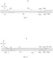
- Fig. 8 shows a partial enlarged view at part B of the Fig. 7 .
- the through hole 32a includes a first hole segment 321a, a second hole segment 322a and a first connecting face 323a connecting the first hole segment 321a and the second hole segment 322a.
- a projection area of the first hole segment 321a is smaller than a projection area of the second hole segment 322a in a thickness direction X, the first hole segment 321a is located at a side of the second hole segment 322a close to an interior of the casing 31, and an inner wall of the second hole segment 322a is configured to fit with a peripheral side face of the pressure relief mechanism 34.
- the projection area of the first hole segment 321a is smaller than the projection area of the second hole segment 322a in a thickness direction X.
- a radial size of the first hole segment 321a is smaller than a radial size of the second hole segment 322a.
- the "radial” here may be a direction that passes through a geometric center of the through hole 32a and is perpendicular to an axial direction of the through hole 32a. Therefore, a circular hole, a square hole, a runway-shaped hole, an elliptical holes, a waist-shaped hole and the like all have the radial sizes.
- first hole segment 321a is arranged on the side of the second hole segment 322a close to the interior of the casing 31, that is, the first hole segment 321a is arranged on the side of the second hole segment 322a close to the electrode assembly 33. Since the inner wall of the second hole segment 322a is used to fit with the peripheral side face of the pressure relief mechanism 34, the pressure relief mechanism 34 is spaced apart from the electrode assembly 33 with at least the first hole segment 321a therebetween.
- the pressure relief mechanism 34 and the electrode assembly 33 are arranged to be spaced apart from each other, so that it can reduce the risk of the electrode assembly 33 exerting the pressure on the pressure relief mechanism 34 due to the electrode assembly 33 contacting with the pressure relief mechanism 34 to be impacted or vibrated, and it is beneficial to reducing the risk of the electrode assembly 33 affecting the normal operation of the pressure relief mechanism 34.
- the pressure relief mechanism 34 can work normally, which is beneficial to ensuring the safety performance of the battery cell 30.
- the pressure relief mechanism 34 can be connected to the first connecting face 323a, the first hole segment 321a can be set to have a certain thickness, so that the first wall 32 can provide sufficient support for the pressure relief mechanism 34, and the working reliability of the pressure relief mechanism 34 can be further improved.
- the size of the first hole segment 321a in the thickness direction X is not limited, and the purpose of spacing the electrode assembly 33 from the pressure relief mechanism 34 can be achieved.
- the battery cell 30 provided by the above embodiments can improve the safety performance of the battery cell 30 to a certain extent, it is still unsatisfactory. For this reason, the inventors conducted further research and found that when the battery cell 30 is in operation, the internal electrode assembly 33 has the risk of contacting the pressure relief mechanism 34 and affecting the actuating pressure of the pressure relief mechanism 34. Thus, the working safety of the battery cell 30 will still be affected.
- the size T1 of the first hole segment 321a satisfies: T1 ⁇ 0.3mm.
- T1 may be 0.3mm, 0.5mm, 0.6mm, 0.8mm or the like.
- T1 ⁇ 0.3mm that is, setting the minimum distance between the pressure relief mechanism 34 and the electrode assembly 33 to be 0.3mm
- the size of the first hole segment 321a is T1
- the size of the second hole segment 322a is T2
- T1+T2 ⁇ 0.5mm
- the first hole segment 321a in order for the first hole segment 321a to have the function of isolating the pressure relief mechanism 34 from the electrode assembly 33, and due to the process restriction, for example, when the first hole segment 321a and the second hole segment 322a are formed by stamping or other processes, if the size of the first hole segment 321a in the thickness direction X is small, it cannot be guaranteed that the deformation of the first hole segment 321a meets the tolerance requirements, and thus, the minimum size T1 of the first hole segment 321a is 0.2mm.
- the minimum size of the pressure relief mechanism 34 in the thickness direction X is 0.3mm.
- the minimum size T2 of the second hole segment 322a is 0.3 mm.
- the maximum value of T1+T2 is not limited, as long as the impact of the relevant parts on the normal operation of the pressure relief mechanism 34 is reduced on the basis of meeting the relevant processing.
- T1+T2 ⁇ 3mm In some embodiments, T1+T2 ⁇ 3mm.
- T1+T2 can be 0.3mm, 0.5mm, 1mm, 2mm, 3mm or the like.
- each of the first hole segment 321a and the second hole segment 322a has the sufficient size, it is beneficial to reducing the thickness of the first wall 32 as much as possible, so as to achieve the lightweight of the battery cell 30 and improve the volume energy density of the battery cell 30.
- the pressure relief mechanism 34 includes a body 341 and a connecting part 342, the connecting part 342 is arranged around the body 341 and abuts against the first connecting face 323a.
- the body 341 includes a basal region 341a and a weak region 341b, and an burst stress of the weak region 341b is smaller than an burst stress of the basal region 341a.
- the connecting part 342 is used to achieve the connection between the pressure relief mechanism 34 and the first connecting face 323a, in order to improve the connection strength between the pressure relief mechanism 34 and the first wall 32.
- the connecting part 342 can be connected to the first connecting face 323a by means of bonding, welding, clamping or the like.
- the connecting part 342 is arranged around the body 341, a circumference of the pressure relief mechanism 34 is connected to the first connecting face 323a, so that it is conducive to ensuring the connection strength between the pressure relief mechanism 34 and the first connecting face 323a.
- the weak region 341b may be arranged in a circular shape, or the weak region 341b may be arranged as a portion of the circular shape.
- the rupture stress of the weak region 341b is smaller than the rupture stress of the basal region 341a, and then the maximum stress that weak region 341b can withstand is smaller than the maximum stress of the basal region 341a, which stress can be compressive stress, shear stress, or tensile stress, etc.
- the pressure of the gas inside battery cell 30 on the pressure relief mechanism 34 gradually increases.
- the weak region 341b ruptures firstly to achieve the pressure relief in the battery cell 30.
- the materials of weak region 341b and basal region 341a may be the same, but the size of weak region 341b in the thickness direction X is smaller than the size of basal region 341a in the thickness direction X, that is, a notch can be formed at a portion of the pressure relief mechanism 34 corresponding to the weak region 341b, and the weak region 341b is provided with an appropriate thickness according to the specific pressure threshold of the pressure relief mechanism 34 to ensure the timely rupture of the weak region 341b when the internal pressure of the battery cell 30 reaches the threshold.
- the materials of weak region 341b and basal region 341a are different, and the structural strength of the material of the weak region 341b is lower than the structural strength of the material of the basal region 341a. Still alternatively, both the materials and the sizes of the weak region 341b and the substrate region 341a in the thickness direction X are different. Specifically, it can be set according to the actual needs, as long as the rupture stress of the weak region 341b is lower than the rupture stress of the basal region 341a.
- the rupture stress of the weak region 341b is lower than he rupture stress of the basal region 341a, so that the specific value of the rupture stress of the weak region 341b can be set as needed to ensure that the weak region 341b opens or ruptures firstly when the internal pressure of the battery cell 30 reaches the threshold, in order to discharge the gas in the battery cell 30 in time.
- the shape of a gas-exhausting channel during the pressure relief mechanism 34 opening can be set, so as to achieve the purpose of discharging gas in the battery cell 30 quickly, which is conducive to further improving the working safety of the battery cell 30.
- a projection of the weak region 341b in the thickness direction X is located within the first hole segment 321a, and the weak region 341b is spaced apart from the inner wall of the second hole segment 322a in a direction perpendicular to the thickness direction X.
- the weak region 341b is located in the first hole segment 321a, so that the gas pressure in the battery cell 30 can affect the weak region 341b, thereby causing the weak region 341b to rupture or burst under the pressure.
- the weak region 341b is spaced apart from the inner wall of the second hole segment 322a, so that it is beneficial to reducing the negative impact of the inner wall of the second hole segment 322a on the normal rupture of the weak region 341b, reducing the risk of the weak region 341b not being able to rupture or burst normally, or reducing the risk of difficulty of discharge of the gas in the battery cell 30 due to the impact of the inner wall of the second hole segment 322a on the shape of the weak region 341b after rupture.
- a size of the connecting part 342 denoted as S1 and a width of the first connecting face 323a denoted as D1 satisfy S1 ⁇ D1, in which the first direction Y is a direction passing through the geometric center of the pressure relief mechanism 34 and perpendicular to the thickness direction X.
- Fig. 9 shows another partial enlarged view at part B of the Fig. 7 .
- the through hole 32a further includes a third hole segment 324a and a second connecting face 325a connecting the third hole segment 324a with the second hole segment 322a.
- a projection area of the third hole segment 324a is larger than a projection area of the second hole segment 322a.
- a width D2 of the second connecting face 325a satisfies: D2 ⁇ 0.5mm, and the first direction Y is a direction passing through the geometric center of the pressure relief mechanism 34 and perpendicular to the thickness direction X.
- the third hole segment 324a is located on a side of the second hole segment 322a away from the first hole segment 321a.
- a projection area of the third hole segment 324a is larger than a projection area of the second hole segment 322a
- a radial size of the third hole segment 324a is larger than a radial size of the second hole segment 322a.
- an orthographic projection of the second hole segment 322a in the thickness direction X can be completely located within an orthographic projection of the third hole segment 324a.
- the minimum size of the welding mark is 0.3mm.
- the width D2 of the third hole segment 324a satisfies: D2 ⁇ 0.5mm.
- the size of D2 can be reasonably set according to needs, and on the premise that the normal welding requirements of the pressure relief mechanism 34 and the first wall 32 can be met, the size of the through hole 32a can be set suitably size, which is not limited here
- D2 ⁇ 1.2mm In some optional embodiments, D2 ⁇ 1.2mm.
- D2 may be 0.5mm, 0.6mm, 0.8mm, 1mm, 1.2mm or the like.
- the width of the second connecting face 325a in the first direction Y can be reduced as small as possible, thereby reducing the space of the first wall 32 occupied by the pressure relief mechanism 34, so that it is beneficial to reducing the size of the first wall 32 and increasing the volume energy density of the battery cell 30.
- Fig. 10 shows another partial enlarged view at part B of the Fig. 7 .
- the battery cell 30 further includes a protective member 35, the protective member 35 is connected to the first wall 32 and arranged at a side of the pressure relief mechanism 34 close to an exterior of the casing 31, and in the thickness direction, the minimum distance h between the protective member 35 and the pressure relief mechanism 34 satisfies: h ⁇ 0.2mm.
- the protective member 35 can be in the shape of a film and include materials such as PET (Polyethylene terephthalate).
- the protective member 35 can be connected to an outer surface of a side of the first wall 32 away from the electrode assembly 33, or the protective member 35 can be arranged in the through hole 32a and cover the pressure relief mechanism 34.
- the minimum distance h between the protective member 35 and the pressure relief mechanism 34 may be 0.2mm, 0.3mm, 0.5mm or the like.
- the pressure relief mechanism 34 can be protected to reduce the scratch and other injuries of the pressure relief mechanism 34 caused by the foreign objects outside the battery cell 30.
- a cavity among the hole wall of the protective member 35, the through hole 32a and the pressure relief mechanism 34 is formed, so that it is beneficial to achieving the actuation of the pressure relief mechanism 34 when the pressure in the battery cell 30 reaches the threshold and reducing the risk of adverse effects of protective member 35 on the normal actuation of the pressure relief mechanism 34.
- the minimum distance h between the protective member 35 and the pressure relief mechanism 34 satisfies the above relationship, so that it is conducive to the normal actuation of the pressure relief mechanism 34 when the internal pressure of the battery cell 30 reaches the threshold, reducing the risk of adverse effects of protective member 35 on the normal actuation of the pressure relief mechanism 34 which may lead to the failure of the pressure relief mechanism 34 to actuate normally.
- the through hole 32a includes a third hole segment 324a, a fourth hole segment 326a and a third connecting face 327a connecting the third hole segment 324a and the fourth hole segment 326a.
- the third hole segment 324a is located between the second hole segment 322a and the fourth hole segment 326a.
- a projection area of the third hole segment 324a is smaller than a projection area of the fourth hole segment 326a.
- the protective member 35 is connected to the third connecting face 327a.
- the maximum size of the protective member 35 is smaller than or equal to a size of the fourth hole segment 326a.
- the projection area of the third hole segment 324a is smaller than the projection area of the fourth hole segment 326a, so that in the thickness direction X, an orthographic projection of the third hole segment 324a is completely located within an orthographic projection of the fourth hole segment 326a in the case that the axial direction of the through hole 32a is parallel to the thickness direction X, that is, a radial size of the third hole segment 324a is smaller than a radial size of the fourth hole segment 326a.
- the protective member 35 can be connected to the third connecting face 327a by bonding, clamping or hot melt, and the third connecting face 327a provides a certain support to the protective member 35.
- the maximum size of the protective member 35 is less than or equal to the size of the fourth hole segment 326a, and the protective member 35 is completely located within the fourth hole segment 326a.
- the protective member 35 is bonded to the third connecting face 327a.
- the bonding connection can ensure the connection strength between the protective member 35 and the third connecting face 327a, so that during the normal operation of the battery cell 30, the protective member 35 has a protective effect on the pressure relief mechanism 34.
- the actuating force can damage the bonding connection between the protective member 35 and the third connecting face 327a, so that the battery cell 30 can release the pressure normally.
- a distance h1 between an edge of the protective member 35 and an inner wall of the third hole segment 324a satisfies: h1 ⁇ 0.5mm.
- h1 may be 0.5mm, 0.8mm, 1mm, 1.2mm, 1.5mm, 2mm or the like.
- the distance between the edge of the protective member 35 and the inner wall of the third hole segment 324a can be equal to a bonding connection width between the protective member 35 and the third connecting face 327a. Therefore, by defining h1 ⁇ 0.5mm, that is, the bonding connection width between the protective member 35 and the third connecting face 327a satisfies the above relationship, so that it is beneficial to improving the connection reliability between the protective member 35 and the third connecting face 327a.
- a distance w between an outer edge of the protective member 35 and an inner wall of the fourth hole segment 326a satisfies: 0.2mm ⁇ w ⁇ 3mm, and the first direction Y is a distance passing through the geometric center of the pressure relief mechanism 34 and perpendicular to the thickness direction X.
- w may be 0.2mm, 0.5mm, 0.6mm, 0.8mm, 1mm, 1.2mm, 1.5mm, 1.8mm, 2mm, 2.5mm, 3mm or the like.
- a positioning tolerance being 0.2mm can be reserved for the positioning of the protective member 35 in the fourth hole segment 326a, so that the risk of the interference between the protective member 35 and the first wall 32 can be reduced.
- w ⁇ 3mm the risk of the interference between the protective member 35 and the first wall 32 can be reduced, and it is beneficial to reducing the space of the first wall 32 occupied by the fourth hole segment 326a in the first direction Y, thereby facilitating integrating other parts on the first wall 32, or ensuring a cooling area of a cooling member of the battery 10 on the first wall 32 of the battery cell 30 after the battery cells 30 are connected to form the battery 10.
- the casing 31 includes a casing body 311 and an end cover 312, the casing body 311 is provided with an opening 311a, and the end cover 312 is used to cover the opening 311a.
- the pressure relief mechanism 34 is arranged on the casing body 311, or the pressure relief mechanism 34 is arranged on the end cover 312.
- the pressure relief mechanism 34 is arranged on the end cover 312, or the pressure relief mechanism is arranged on the casing body 311, both of which can achieve the discharge of gas in the battery cell 30.
- the specific position of the pressure relief mechanism 34 can be flexibly arranged according to actual needs, so as to reserve a sufficient space for the integration of other related structures in the battery cell 30.
- the pressure relief mechanism is arranged on the casing body 311, and the casing body 311 includes the first wall 32, a second wall 3111 and two third walls 3112.
- the first wall 32 and the second wall 3111 are opposite to each other, and the two third walls 3112 are opposite to each other.
- Each of the third walls 3112 is connected to the first wall 32 and the second wall 3111.
- the structures or shapes of the first wall 32 and the second wall 3111 may be the same, or the second wall 3111 and the first wall 32 may have different structures and shapes respectively.
- the third walls 3112 are connected the first wall 32 and the second wall 3111, and the first wall 32, the second wall 3111 and the third walls 3112 are jointly enclosed on the peripheral side of the electrode assembly 33.
- the pressure relief mechanism 34 can be arranged at any position on the first wall 32, so that on the premise of ensuring the normal operation of the pressure relief mechanism 34, the position of the pressure relief mechanism 34 can be reasonably set according to the spatial layout of various parts in the battery cell 30.
- a surface area of the first wall 32 is smaller than a surface area of each of the third walls 3112.
- the pressure relief mechanism 34 is arranged on the wall of the casing body 311 with a smaller area. In this way, during the process of forming the battery 10 or battery module 20 from the battery cell 30, a side surface of the battery cell 30 with the larger area, such as a surface corresponding to the third wall 3112, can be attached to the third wall 3112, so as to improve the space utilization rate of the interior of the battery 10 and the energy density of the battery 10.
- the casing body 311 is provided with two openings 311a opposite to each other, two end covers 312 are provided, and the two end covers 312 cover the two openings 311a respectively.
- the casing body 311 is provided with two openings 311a, and two end covers 312 cover the two openings 311a respectively.
- the electrode assembly 33 is placed into the casing body 311 firstly, and then the two end covers 312 cover the openings 311a respectively, so that it can make the assembly process of battery cell 30 more convenient and efficient.
- the battery 10 provided by the embodiments of the present application includes the battery cell 30 according to any one of the embodiments as described above.
- the battery 10 provided by the embodiments of the present application has the same technical effect due to using the battery cell 30 according to any one of the embodiments as described above, which will not be repeated here.
- An electricity-consuming apparatus provided by the embodiments of the present application includes the battery 10 according to embodiments as described above, and the battery 10 is used to supply an electric power.
- the electricity-consuming apparatus provided by the embodiments of the present application has the same technical effect due to using the battery 10 according to the embodiments as described above, which will not be repeated here.
Landscapes
- Chemical & Material Sciences (AREA)
- Chemical Kinetics & Catalysis (AREA)
- Electrochemistry (AREA)
- General Chemical & Material Sciences (AREA)
- Engineering & Computer Science (AREA)
- Manufacturing & Machinery (AREA)
- Sealing Battery Cases Or Jackets (AREA)
- Gas Exhaust Devices For Batteries (AREA)
- Battery Mounting, Suspending (AREA)
- Secondary Cells (AREA)
Applications Claiming Priority (2)
| Application Number | Priority Date | Filing Date | Title |
|---|---|---|---|
| PCT/CN2022/078375 WO2023159588A1 (fr) | 2022-02-28 | 2022-02-28 | Élément de batterie, batterie et dispositif électrique |
| PCT/CN2022/102613 WO2023159840A1 (fr) | 2022-02-28 | 2022-06-30 | Cellule de batterie, batterie et dispositif électrique |
Publications (2)
| Publication Number | Publication Date |
|---|---|
| EP4418432A1 true EP4418432A1 (fr) | 2024-08-21 |
| EP4418432A4 EP4418432A4 (fr) | 2025-07-30 |
Family
ID=84133333
Family Applications (3)
| Application Number | Title | Priority Date | Filing Date |
|---|---|---|---|
| EP22927869.2A Pending EP4379928A4 (fr) | 2022-02-28 | 2022-02-28 | Élément de batterie, batterie et dispositif électrique |
| EP22928110.0A Pending EP4418432A4 (fr) | 2022-02-28 | 2022-06-30 | Cellule de batterie, batterie et dispositif électrique |
| EP22928117.5A Pending EP4425674A4 (fr) | 2022-02-28 | 2022-06-30 | Élément de batterie, batterie et appareil électrique |
Family Applications Before (1)
| Application Number | Title | Priority Date | Filing Date |
|---|---|---|---|
| EP22927869.2A Pending EP4379928A4 (fr) | 2022-02-28 | 2022-02-28 | Élément de batterie, batterie et dispositif électrique |
Family Applications After (1)
| Application Number | Title | Priority Date | Filing Date |
|---|---|---|---|
| EP22928117.5A Pending EP4425674A4 (fr) | 2022-02-28 | 2022-06-30 | Élément de batterie, batterie et appareil électrique |
Country Status (6)
| Country | Link |
|---|---|
| US (3) | US20240250347A1 (fr) |
| EP (3) | EP4379928A4 (fr) |
| JP (2) | JP7799034B2 (fr) |
| KR (1) | KR102951204B1 (fr) |
| CN (5) | CN116982205A (fr) |
| WO (3) | WO2023159588A1 (fr) |
Families Citing this family (11)
| Publication number | Priority date | Publication date | Assignee | Title |
|---|---|---|---|---|
| CN119404361A (zh) * | 2023-01-04 | 2025-02-07 | 宁德时代新能源科技股份有限公司 | 外壳部件、电池单体、电池及用电设备 |
| WO2024152293A1 (fr) * | 2023-01-19 | 2024-07-25 | 宁德时代新能源科技股份有限公司 | Élément de batterie, batterie et appareil électrique |
| CN118017144A (zh) * | 2023-03-24 | 2024-05-10 | 宁德时代新能源科技股份有限公司 | 电池单体、电池及用电设备 |
| CN220121962U (zh) * | 2023-04-18 | 2023-12-01 | 宁德时代新能源科技股份有限公司 | 电池单体、电池和用电装置 |
| CN116345057B (zh) * | 2023-05-26 | 2023-09-22 | 宁德时代新能源科技股份有限公司 | 电池单体、电池及用电装置 |
| CN116581466B (zh) * | 2023-07-11 | 2023-10-27 | 宁德时代新能源科技股份有限公司 | 泄压部件、电池单体、电池及用电装置 |
| EP4664645A4 (fr) * | 2023-11-21 | 2026-03-25 | Contemporary Amperex Technology Co Ltd | Élément de batterie, batterie et appareil électrique |
| CN117638254B (zh) * | 2024-01-26 | 2024-04-26 | 宁德新能源科技有限公司 | 一种电极组件及电池 |
| US20260005388A1 (en) * | 2024-06-26 | 2026-01-01 | GM Global Technology Operations LLC | Battery assembly including prismatic can battery cells having a side mounted vent cap |
| WO2026025389A1 (fr) * | 2024-07-31 | 2026-02-05 | 宁德时代新能源科技股份有限公司 | Élément de batterie, batterie et dispositif électrique |
| EP4726865A1 (fr) * | 2024-10-09 | 2026-04-15 | ABB Schweiz AG | Agencement de batterie et procédé de fabrication de l'agencement de batterie |
Family Cites Families (23)
| Publication number | Priority date | Publication date | Assignee | Title |
|---|---|---|---|---|
| CN101685850A (zh) * | 2008-09-26 | 2010-03-31 | 深圳市比克电池有限公司 | 一种锂电池缓冲防爆装置及防爆锂电池 |
| KR20110003866A (ko) * | 2009-07-06 | 2011-01-13 | 에스비리모티브 주식회사 | 리튬 이온 전지 |
| KR101101093B1 (ko) * | 2009-11-26 | 2012-01-03 | 삼성에스디아이 주식회사 | 이차전지용 케이스 및 이를 이용한 리튬 이차전지 |
| CN102136552B (zh) * | 2010-01-27 | 2015-11-25 | 深圳市比克电池有限公司 | 电池保护装置、电池及电池保护装置的制作方法 |
| JP2014216304A (ja) * | 2013-04-30 | 2014-11-17 | 栗田工業株式会社 | 蓄電デバイス用ガス吸収材及びこれを用いた蓄電デバイス、並びに当該蓄電デバイスを用いた電気機器及び電子機器 |
| JP6299384B2 (ja) * | 2014-04-24 | 2018-03-28 | 株式会社豊田自動織機 | 蓄電装置 |
| JP6686286B2 (ja) * | 2015-03-30 | 2020-04-22 | 三洋電機株式会社 | 角形二次電池及びそれを用いた組電池 |
| JP6816353B2 (ja) * | 2015-10-26 | 2021-01-20 | 株式会社Gsユアサ | 蓄電素子 |
| CN205657091U (zh) * | 2016-05-16 | 2016-10-19 | 宁德时代新能源科技股份有限公司 | 二次电池及其壳体 |
| CN206098459U (zh) * | 2016-07-08 | 2017-04-12 | 宁德时代新能源科技股份有限公司 | 二次电池及其电池壳体组件 |
| JP2018092726A (ja) | 2016-11-30 | 2018-06-14 | 株式会社豊田自動織機 | 蓄電装置 |
| JP6850208B2 (ja) | 2017-06-19 | 2021-03-31 | 株式会社Gsユアサ | 蓄電素子及び蓄電モジュール |
| CN108123084A (zh) * | 2018-02-02 | 2018-06-05 | 华霆(合肥)动力技术有限公司 | 软包电池安装结构及电池模组 |
| CN112259937B (zh) | 2019-07-05 | 2025-02-25 | 宁德时代新能源科技股份有限公司 | 电池包 |
| CN111009679A (zh) * | 2019-12-25 | 2020-04-14 | 天津荣盛盟固利新能源科技有限公司 | 一种三电极电芯、三电极软包电池及其制备方法 |
| JP2021190360A (ja) * | 2020-06-02 | 2021-12-13 | ブルースカイテクノロジー株式会社 | リチウムイオンバッテリーパック |
| WO2022006894A1 (fr) | 2020-07-10 | 2022-01-13 | 宁德时代新能源科技股份有限公司 | Batterie et appareil associé correspondant, procédé de préparation et dispositif de préparation |
| CN213546446U (zh) * | 2020-07-10 | 2021-06-25 | 宁德时代新能源科技股份有限公司 | 电池单体、电池和用电设备 |
| CN114175379B (zh) | 2020-07-10 | 2023-11-28 | 宁德时代新能源科技股份有限公司 | 电池及其相关装置、制备方法和制备设备 |
| CN212991189U (zh) * | 2020-07-10 | 2021-04-16 | 宁德时代新能源科技股份有限公司 | 电池盒、电池单体、电池和用电设备 |
| EP3965219B1 (fr) * | 2020-07-10 | 2023-06-07 | Contemporary Amperex Technology Co., Limited | Mécanisme de décompression, boîtier de batterie, cellule de batterie, batterie, procédé de préparation et dispositif |
| CN112736363B (zh) * | 2021-04-01 | 2021-07-20 | 江苏时代新能源科技有限公司 | 电池单体、电池、用电装置、制备电池单体的方法及设备 |
| CN216250905U (zh) * | 2021-09-10 | 2022-04-08 | 厦门海辰新能源科技有限公司 | 电池和用电设备 |
-
2022
- 2022-02-28 EP EP22927869.2A patent/EP4379928A4/fr active Pending
- 2022-02-28 WO PCT/CN2022/078375 patent/WO2023159588A1/fr not_active Ceased
- 2022-02-28 CN CN202280007965.6A patent/CN116982205A/zh active Pending
- 2022-02-28 JP JP2024509011A patent/JP7799034B2/ja active Active
- 2022-02-28 KR KR1020247004537A patent/KR102951204B1/ko active Active
- 2022-06-30 CN CN202280022583.0A patent/CN117044023A/zh active Pending
- 2022-06-30 CN CN202280016995.3A patent/CN116982207A/zh active Pending
- 2022-06-30 CN CN202221669813.6U patent/CN217903284U/zh active Active
- 2022-06-30 WO PCT/CN2022/102613 patent/WO2023159840A1/fr not_active Ceased
- 2022-06-30 CN CN202221655744.3U patent/CN218274967U/zh active Active
- 2022-06-30 WO PCT/CN2022/103094 patent/WO2023159847A1/fr not_active Ceased
- 2022-06-30 EP EP22928110.0A patent/EP4418432A4/fr active Pending
- 2022-06-30 EP EP22928117.5A patent/EP4425674A4/fr active Pending
-
2024
- 2024-03-04 US US18/594,020 patent/US20240250347A1/en active Pending
- 2024-05-21 US US18/669,558 patent/US20240313339A1/en active Pending
- 2024-05-28 US US18/675,724 patent/US20240322351A1/en active Pending
-
2025
- 2025-12-25 JP JP2025281975A patent/JP2026062831A/ja active Pending
Also Published As
| Publication number | Publication date |
|---|---|
| JP2026062831A (ja) | 2026-04-10 |
| CN117044023A (zh) | 2023-11-10 |
| CN116982205A (zh) | 2023-10-31 |
| EP4425674A4 (fr) | 2025-05-21 |
| US20240322351A1 (en) | 2024-09-26 |
| US20240250347A1 (en) | 2024-07-25 |
| CN217903284U (zh) | 2022-11-25 |
| EP4379928A1 (fr) | 2024-06-05 |
| EP4418432A4 (fr) | 2025-07-30 |
| CN116982207A (zh) | 2023-10-31 |
| WO2023159840A1 (fr) | 2023-08-31 |
| US20240313339A1 (en) | 2024-09-19 |
| WO2023159588A1 (fr) | 2023-08-31 |
| KR20240032987A (ko) | 2024-03-12 |
| WO2023159847A1 (fr) | 2023-08-31 |
| JP7799034B2 (ja) | 2026-01-14 |
| EP4425674A1 (fr) | 2024-09-04 |
| KR102951204B1 (ko) | 2026-04-10 |
| CN218274967U (zh) | 2023-01-10 |
| EP4379928A4 (fr) | 2025-07-23 |
| JP2024531286A (ja) | 2024-08-29 |
Similar Documents
| Publication | Publication Date | Title |
|---|---|---|
| EP4418432A1 (fr) | Cellule de batterie, batterie et dispositif électrique | |
| EP3965216B1 (fr) | Batterie et appareil associé correspondant, procédé de préparation et dispositif de préparation | |
| JP7419533B2 (ja) | 電池、その関連装置、製造方法及び製造機器 | |
| EP3965214B1 (fr) | Batterie et son appareil associé et son procédé de préparation et son dispositif de préparation | |
| US11699829B2 (en) | Box of battery, battery, power consumpiion apparatus, method for producing battery and apparatus for producing battery | |
| CN116171505B (zh) | 电池单体及其制造方法和制造系统、电池以及用电装置 | |
| CN216250985U (zh) | 电池单体、电池和用电设备 | |
| EP4485655B1 (fr) | Batterie et dispositif électrique | |
| US20220013855A1 (en) | Battery box, battery cell, battery, and method and apparatus for preparing battery box | |
| CN218513629U (zh) | 电池单体、电池及用电装置 | |
| EP4507117A1 (fr) | Batterie et appareil électrique | |
| US20240222783A1 (en) | Battery and electrical device | |
| US12548837B2 (en) | Battery cell, manufacturing method and manufacturing system thereof, battery, and powered device | |
| US20250079627A1 (en) | Battery cell, battery, and power consuming device | |
| US20250149743A1 (en) | Battery cell, battery and electrical apparatus | |
| CN218414923U (zh) | 电池单体的壳体、电池单体、电池和用电设备 | |
| JP7574429B2 (ja) | 圧力解放装置、電池セル、電池および電気設備 | |
| JP7536114B2 (ja) | 電池セル、電池、電力消費機器、電池セルの製造方法と機器 | |
| EP4415153A1 (fr) | Élément de batterie, batterie et dispositif électrique | |
| WO2024059963A1 (fr) | Élément de batterie, batterie et appareil électrique | |
| US20250337096A1 (en) | Battery cell, battery, and electric apparatus | |
| US11973243B2 (en) | Battery, power consumption device, and method and device for producing battery | |
| EP4300690B1 (fr) | Batterie, dispositif électrique, et procédé de fabrication de batterie | |
| EP4557467A1 (fr) | Élément de batterie, batterie et dispositif électrique | |
| EP4510350A1 (fr) | Appareil de libération de pression, élément de batterie, batterie, dispositif électrique et procédé de fabrication |
Legal Events
| Date | Code | Title | Description |
|---|---|---|---|
| STAA | Information on the status of an ep patent application or granted ep patent |
Free format text: STATUS: THE INTERNATIONAL PUBLICATION HAS BEEN MADE |
|
| PUAI | Public reference made under article 153(3) epc to a published international application that has entered the european phase |
Free format text: ORIGINAL CODE: 0009012 |
|
| STAA | Information on the status of an ep patent application or granted ep patent |
Free format text: STATUS: REQUEST FOR EXAMINATION WAS MADE |
|
| 17P | Request for examination filed |
Effective date: 20240515 |
|
| AK | Designated contracting states |
Kind code of ref document: A1 Designated state(s): AL AT BE BG CH CY CZ DE DK EE ES FI FR GB GR HR HU IE IS IT LI LT LU LV MC MK MT NL NO PL PT RO RS SE SI SK SM TR |
|
| RAP1 | Party data changed (applicant data changed or rights of an application transferred) |
Owner name: CONTEMPORARY AMPEREX TECHNOLOGY(HONG KONG) LIMITED |
|
| DAV | Request for validation of the european patent (deleted) | ||
| DAX | Request for extension of the european patent (deleted) | ||
| A4 | Supplementary search report drawn up and despatched |
Effective date: 20250630 |
|
| RIC1 | Information provided on ipc code assigned before grant |
Ipc: H01M 50/342 20210101AFI20250624BHEP Ipc: H01M 50/10 20210101ALI20250624BHEP Ipc: H01M 50/244 20210101ALI20250624BHEP |