EP4418488A1 - System zum laden, kühlen und erwärmen von akkumulatoren - Google Patents
System zum laden, kühlen und erwärmen von akkumulatoren Download PDFInfo
- Publication number
- EP4418488A1 EP4418488A1 EP23156735.5A EP23156735A EP4418488A1 EP 4418488 A1 EP4418488 A1 EP 4418488A1 EP 23156735 A EP23156735 A EP 23156735A EP 4418488 A1 EP4418488 A1 EP 4418488A1
- Authority
- EP
- European Patent Office
- Prior art keywords
- accumulator
- receiving
- designed
- charging
- receiving device
- Prior art date
- Legal status (The legal status is an assumption and is not a legal conclusion. Google has not performed a legal analysis and makes no representation as to the accuracy of the status listed.)
- Withdrawn
Links
Images

Classifications
-
- H—ELECTRICITY
- H02—GENERATION; CONVERSION OR DISTRIBUTION OF ELECTRIC POWER
- H02J—ELECTRIC POWER NETWORKS; CIRCUIT ARRANGEMENTS OR SYSTEMS FOR SUPPLYING OR DISTRIBUTING ELECTRIC POWER; SYSTEMS FOR STORING ELECTRIC ENERGY
- H02J7/00—Circuit arrangements for charging or discharging batteries or for supplying loads from batteries
- H02J7/70—Circuit arrangements for charging or discharging batteries or for supplying loads from batteries characterised by the mechanical construction
- H02J7/751—Circuit arrangements for charging or discharging batteries or for supplying loads from batteries characterised by the mechanical construction concerning the insertion or the connection of the batteries
-
- H—ELECTRICITY
- H01—ELECTRIC ELEMENTS
- H01M—PROCESSES OR MEANS, e.g. BATTERIES, FOR THE DIRECT CONVERSION OF CHEMICAL ENERGY INTO ELECTRICAL ENERGY
- H01M10/00—Secondary cells; Manufacture thereof
- H01M10/42—Methods or arrangements for servicing or maintenance of secondary cells or secondary half-cells
- H01M10/4207—Methods or arrangements for servicing or maintenance of secondary cells or secondary half-cells for several batteries or cells simultaneously or sequentially
-
- H—ELECTRICITY
- H01—ELECTRIC ELEMENTS
- H01M—PROCESSES OR MEANS, e.g. BATTERIES, FOR THE DIRECT CONVERSION OF CHEMICAL ENERGY INTO ELECTRICAL ENERGY
- H01M10/00—Secondary cells; Manufacture thereof
- H01M10/42—Methods or arrangements for servicing or maintenance of secondary cells or secondary half-cells
- H01M10/4221—Methods or arrangements for servicing or maintenance of secondary cells or secondary half-cells with battery type recognition
-
- H—ELECTRICITY
- H01—ELECTRIC ELEMENTS
- H01M—PROCESSES OR MEANS, e.g. BATTERIES, FOR THE DIRECT CONVERSION OF CHEMICAL ENERGY INTO ELECTRICAL ENERGY
- H01M10/00—Secondary cells; Manufacture thereof
- H01M10/42—Methods or arrangements for servicing or maintenance of secondary cells or secondary half-cells
- H01M10/48—Accumulators combined with arrangements for measuring, testing or indicating the condition of cells, e.g. the level or density of the electrolyte
-
- H—ELECTRICITY
- H01—ELECTRIC ELEMENTS
- H01M—PROCESSES OR MEANS, e.g. BATTERIES, FOR THE DIRECT CONVERSION OF CHEMICAL ENERGY INTO ELECTRICAL ENERGY
- H01M10/00—Secondary cells; Manufacture thereof
- H01M10/42—Methods or arrangements for servicing or maintenance of secondary cells or secondary half-cells
- H01M10/48—Accumulators combined with arrangements for measuring, testing or indicating the condition of cells, e.g. the level or density of the electrolyte
- H01M10/482—Accumulators combined with arrangements for measuring, testing or indicating the condition of cells, e.g. the level or density of the electrolyte for several batteries or cells simultaneously or sequentially
-
- H—ELECTRICITY
- H01—ELECTRIC ELEMENTS
- H01M—PROCESSES OR MEANS, e.g. BATTERIES, FOR THE DIRECT CONVERSION OF CHEMICAL ENERGY INTO ELECTRICAL ENERGY
- H01M10/00—Secondary cells; Manufacture thereof
- H01M10/42—Methods or arrangements for servicing or maintenance of secondary cells or secondary half-cells
- H01M10/48—Accumulators combined with arrangements for measuring, testing or indicating the condition of cells, e.g. the level or density of the electrolyte
- H01M10/486—Accumulators combined with arrangements for measuring, testing or indicating the condition of cells, e.g. the level or density of the electrolyte for measuring temperature
-
- H—ELECTRICITY
- H01—ELECTRIC ELEMENTS
- H01M—PROCESSES OR MEANS, e.g. BATTERIES, FOR THE DIRECT CONVERSION OF CHEMICAL ENERGY INTO ELECTRICAL ENERGY
- H01M10/00—Secondary cells; Manufacture thereof
- H01M10/60—Heating or cooling; Temperature control
- H01M10/61—Types of temperature control
- H01M10/613—Cooling or keeping cold
-
- H—ELECTRICITY
- H01—ELECTRIC ELEMENTS
- H01M—PROCESSES OR MEANS, e.g. BATTERIES, FOR THE DIRECT CONVERSION OF CHEMICAL ENERGY INTO ELECTRICAL ENERGY
- H01M10/00—Secondary cells; Manufacture thereof
- H01M10/60—Heating or cooling; Temperature control
- H01M10/61—Types of temperature control
- H01M10/615—Heating or keeping warm
-
- H—ELECTRICITY
- H01—ELECTRIC ELEMENTS
- H01M—PROCESSES OR MEANS, e.g. BATTERIES, FOR THE DIRECT CONVERSION OF CHEMICAL ENERGY INTO ELECTRICAL ENERGY
- H01M10/00—Secondary cells; Manufacture thereof
- H01M10/60—Heating or cooling; Temperature control
- H01M10/62—Heating or cooling; Temperature control specially adapted for specific applications
- H01M10/625—Vehicles
-
- H—ELECTRICITY
- H01—ELECTRIC ELEMENTS
- H01M—PROCESSES OR MEANS, e.g. BATTERIES, FOR THE DIRECT CONVERSION OF CHEMICAL ENERGY INTO ELECTRICAL ENERGY
- H01M10/00—Secondary cells; Manufacture thereof
- H01M10/60—Heating or cooling; Temperature control
- H01M10/63—Control systems
-
- H—ELECTRICITY
- H01—ELECTRIC ELEMENTS
- H01M—PROCESSES OR MEANS, e.g. BATTERIES, FOR THE DIRECT CONVERSION OF CHEMICAL ENERGY INTO ELECTRICAL ENERGY
- H01M10/00—Secondary cells; Manufacture thereof
- H01M10/60—Heating or cooling; Temperature control
- H01M10/63—Control systems
- H01M10/633—Control systems characterised by algorithms, flow charts, software details or the like
-
- H—ELECTRICITY
- H01—ELECTRIC ELEMENTS
- H01M—PROCESSES OR MEANS, e.g. BATTERIES, FOR THE DIRECT CONVERSION OF CHEMICAL ENERGY INTO ELECTRICAL ENERGY
- H01M10/00—Secondary cells; Manufacture thereof
- H01M10/60—Heating or cooling; Temperature control
- H01M10/63—Control systems
- H01M10/635—Control systems based on ambient temperature
-
- H—ELECTRICITY
- H01—ELECTRIC ELEMENTS
- H01M—PROCESSES OR MEANS, e.g. BATTERIES, FOR THE DIRECT CONVERSION OF CHEMICAL ENERGY INTO ELECTRICAL ENERGY
- H01M10/00—Secondary cells; Manufacture thereof
- H01M10/60—Heating or cooling; Temperature control
- H01M10/65—Means for temperature control structurally associated with the cells
- H01M10/657—Means for temperature control structurally associated with the cells by electric or electromagnetic means
- H01M10/6571—Resistive heaters
-
- H—ELECTRICITY
- H01—ELECTRIC ELEMENTS
- H01M—PROCESSES OR MEANS, e.g. BATTERIES, FOR THE DIRECT CONVERSION OF CHEMICAL ENERGY INTO ELECTRICAL ENERGY
- H01M50/00—Constructional details or processes of manufacture of the non-active parts of electrochemical cells other than fuel cells, e.g. hybrid cells
- H01M50/20—Mountings; Secondary casings or frames; Racks, modules or packs; Suspension devices; Shock absorbers; Transport or carrying devices; Holders
- H01M50/256—Carrying devices, e.g. belts
-
- H—ELECTRICITY
- H02—GENERATION; CONVERSION OR DISTRIBUTION OF ELECTRIC POWER
- H02J—ELECTRIC POWER NETWORKS; CIRCUIT ARRANGEMENTS OR SYSTEMS FOR SUPPLYING OR DISTRIBUTING ELECTRIC POWER; SYSTEMS FOR STORING ELECTRIC ENERGY
- H02J7/00—Circuit arrangements for charging or discharging batteries or for supplying loads from batteries
- H02J7/40—Circuit arrangements for charging or discharging batteries or for supplying loads from batteries characterised by the exchange of charge or discharge related data
- H02J7/44—Circuit arrangements for charging or discharging batteries or for supplying loads from batteries characterised by the exchange of charge or discharge related data between battery management systems and power sources
-
- H—ELECTRICITY
- H02—GENERATION; CONVERSION OR DISTRIBUTION OF ELECTRIC POWER
- H02J—ELECTRIC POWER NETWORKS; CIRCUIT ARRANGEMENTS OR SYSTEMS FOR SUPPLYING OR DISTRIBUTING ELECTRIC POWER; SYSTEMS FOR STORING ELECTRIC ENERGY
- H02J7/00—Circuit arrangements for charging or discharging batteries or for supplying loads from batteries
- H02J7/50—Circuit arrangements for charging or discharging batteries or for supplying loads from batteries acting upon multiple batteries simultaneously or sequentially
-
- H—ELECTRICITY
- H02—GENERATION; CONVERSION OR DISTRIBUTION OF ELECTRIC POWER
- H02J—ELECTRIC POWER NETWORKS; CIRCUIT ARRANGEMENTS OR SYSTEMS FOR SUPPLYING OR DISTRIBUTING ELECTRIC POWER; SYSTEMS FOR STORING ELECTRIC ENERGY
- H02J7/00—Circuit arrangements for charging or discharging batteries or for supplying loads from batteries
- H02J7/60—Circuit arrangements for charging or discharging batteries or for supplying loads from batteries including safety or protection arrangements
- H02J7/65—Circuit arrangements for charging or discharging batteries or for supplying loads from batteries including safety or protection arrangements against overtemperature
-
- H—ELECTRICITY
- H02—GENERATION; CONVERSION OR DISTRIBUTION OF ELECTRIC POWER
- H02J—ELECTRIC POWER NETWORKS; CIRCUIT ARRANGEMENTS OR SYSTEMS FOR SUPPLYING OR DISTRIBUTING ELECTRIC POWER; SYSTEMS FOR STORING ELECTRIC ENERGY
- H02J7/00—Circuit arrangements for charging or discharging batteries or for supplying loads from batteries
- H02J7/80—Circuit arrangements for charging or discharging batteries or for supplying loads from batteries including monitoring or indicating arrangements
-
- H—ELECTRICITY
- H01—ELECTRIC ELEMENTS
- H01M—PROCESSES OR MEANS, e.g. BATTERIES, FOR THE DIRECT CONVERSION OF CHEMICAL ENERGY INTO ELECTRICAL ENERGY
- H01M10/00—Secondary cells; Manufacture thereof
- H01M10/42—Methods or arrangements for servicing or maintenance of secondary cells or secondary half-cells
- H01M10/425—Structural combination with electronic components, e.g. electronic circuits integrated to the outside of the casing
- H01M2010/4278—Systems for data transfer from batteries, e.g. transfer of battery parameters to a controller, data transferred between battery controller and main controller
-
- H—ELECTRICITY
- H02—GENERATION; CONVERSION OR DISTRIBUTION OF ELECTRIC POWER
- H02J—ELECTRIC POWER NETWORKS; CIRCUIT ARRANGEMENTS OR SYSTEMS FOR SUPPLYING OR DISTRIBUTING ELECTRIC POWER; SYSTEMS FOR STORING ELECTRIC ENERGY
- H02J7/00—Circuit arrangements for charging or discharging batteries or for supplying loads from batteries
- H02J7/485—Circuit arrangements for charging or discharging batteries or for supplying loads from batteries with provisions for charging different types of batteries
-
- Y—GENERAL TAGGING OF NEW TECHNOLOGICAL DEVELOPMENTS; GENERAL TAGGING OF CROSS-SECTIONAL TECHNOLOGIES SPANNING OVER SEVERAL SECTIONS OF THE IPC; TECHNICAL SUBJECTS COVERED BY FORMER USPC CROSS-REFERENCE ART COLLECTIONS [XRACs] AND DIGESTS
- Y02—TECHNOLOGIES OR APPLICATIONS FOR MITIGATION OR ADAPTATION AGAINST CLIMATE CHANGE
- Y02E—REDUCTION OF GREENHOUSE GAS [GHG] EMISSIONS, RELATED TO ENERGY GENERATION, TRANSMISSION OR DISTRIBUTION
- Y02E60/00—Enabling technologies; Technologies with a potential or indirect contribution to GHG emissions mitigation
- Y02E60/10—Energy storage using batteries
Definitions
- the present invention relates to a system with at least one first receiving device for receiving at least one first accumulator, wherein the at least first accumulator contains a temperature sensor for detecting at least one temperature value of the accumulator.
- Accumulators also called batteries as a power supply for a machine tool are widely known in the state of the art. These accumulators usually contain a number of energy storage cells (also called battery cells) that are used and designed to absorb, store and release electrical energy. The absorption of electrical energy into the energy storage cells can also be referred to as charging. The release of electrical energy from the energy storage cells can also be referred to as discharging.
- energy storage cells also called battery cells
- the battery is usually connected to a charging device (also called a charger).
- the charging device supplies electrical energy to the individual energy storage cells of the battery according to a predetermined charging setting (also called charging mode) with fixed parameters for the actual charging process.
- the parameters of the battery should be between minimum and maximum threshold values.
- a battery outside of the threshold values can lead to significantly longer charging times, a lower capacity and/or a lower discharge current value.
- the object of the present invention is to solve the problem described above.
- the object is achieved in particular by a system with at least one first receiving device for receiving at least one first accumulator, wherein the at least first accumulator contains a temperature sensor for detecting at least one temperature value of the accumulator.
- the at least first receiving device contains a charging device for charging the accumulator with electrical energy, a cooling device for cooling the accumulator and a heating device for heating the accumulator.
- the accumulator contains at least one energy storage cell.
- the temperature sensor of the accumulator is designed in particular, but not exclusively, to detect the temperature of the at least one energy storage cell.
- the temperature sensor is designed and positioned such that it detects at least the temperature of the energy storage cell that is located furthest away from an outer wall of the accumulator.
- a diagnostic device may be included for determining at least one parameter of the accumulator.
- the parameters of the accumulator may be the electrical voltage, the capacity, the temperature, the electrical resistance and the like.
- the at least first receiving device may contain at least one display device for outputting at least one release signal or one blocking signal.
- the display device can be designed to output acoustic and/or visual signals.
- a user of the system can be given information about the status of the system and/or a battery with the aid of the display device.
- the receiving device may be designed as a chamber, wherein the chamber has at least one volume for receiving at least one accumulator and at least one resealable Opening for placing at least one accumulator inside the chamber.
- the chamber has at least one volume for receiving at least one accumulator and at least one resealable Opening for placing at least one accumulator inside the chamber.
- At least one second receiving device may be included for receiving at least one second accumulator. This allows several accumulators to be positioned in the system at the same time.
- an acceptance device and a first transport device may be included, wherein the acceptance device is designed to receive at least one accumulator and the first transport device is designed to transport the at least one accumulator to a receiving device.
- a storage device and a second transport device may be included, wherein the storage device is designed for at least temporarily storing at least one accumulator and the second transport device is designed for transporting the at least one accumulator from a receiving device to the storage device.
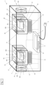
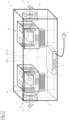
- Figure 1 and 2 shows a system 1 according to the invention with a first receiving device 2a and a second receiving device 2b as well as a control unit 3 according to a first embodiment.
- a first accumulator 4a is positioned in the first receiving device 2a and a second accumulator 4b is positioned in the second receiving device 2b.
- the two accumulators 4a, 4b are identical in the first embodiment. However, it is also possible that the accumulators 4a, 4b are not identical or are designed differently.
- the accumulator 4a, 4b can be releasably connected to a machine tool in order to supply the machine tool with electrical energy.
- the machine tool is not shown in the figures.
- the accumulator 4a, 4b essentially contains a battery housing 5, a number of energy storage cells 5a, a battery interface and a control device 6.
- the energy storage cells 5a can also be referred to as battery cells and are arranged inside the battery housing 5.
- the battery interface is not shown in the figures.
- the battery housing 5 essentially contains a cover element, four side walls and a base element.
- the battery interface is arranged on the outside of the cover element and serves for the electrical or electronic as well as mechanical connection of the battery 4a, 4b to the machine tool or the holding device 2a, 2b.
- the battery interface has a positive contact, a negative contact and a communication contact.
- the positive and negative contacts are used to create an electrical circuit when the battery 4a, 4b is connected to a machine tool or the holding device 2a, 2b.
- the communication contact is used to send and receive data and information in the form of electrical signals.
- the battery 4a, 4b can also contain radio communication (e.g. Bluetooth) or wireless communication.
- the energy storage cells 5a are used to absorb, store and release electrical energy. As indicated in the figures, the energy storage cells 5a are cylindrical in shape and are designed based on lithium-ion technology. Each Energy storage cell 5a contains a contact device at one end which serves to transmit electrical energy. The individual contact devices are connected to the control device 6 via corresponding lines.
- the energy storage cells 5a may also be based on another suitable technology.
- the contact devices are not shown in the figures.
- the cylindrical shape of the energy storage cells 5a is also exemplary, so that any other suitable shape or geometry can be selected.
- the energy storage cells 5a it is also possible for the energy storage cells 5a to be designed as pouch cells.
- the accumulator 4a, 4b may contain both cylindrical energy storage cells 5a and pouch cells.
- the accumulator 4a, 4b it is possible for the accumulator 4a, 4b to contain a single cylindrical energy storage cell 5a and a single pouch cell.
- the control device 6 regulates and controls various functions of the accumulator 4a, 4b. Furthermore, the control device 6 contains a temperature sensor 7 for detecting at least one temperature value of the accumulator 4a, 4b. As indicated in the figures, the temperature sensor 7 is positioned in the middle of the accumulator 4a, 4b, i.e. near the energy storage cell 5a that is furthest away from the walls of the battery housing 5. This energy storage cell 5a usually becomes the warmest during use of the accumulator 4a, 4b and is therefore most susceptible to heat-related damage.
- control device 6 is connected to the energy storage cells 5a and the battery interface via corresponding lines so that electrical energy can reach the battery interface from the energy storage cells 5a via the control device 6.
- a rail device is provided for the releasable mechanical coupling of the accumulator 4a, 4b to the machine tool.
- a locking device serves to releasably connect the accumulator 4a, 4b to the machine tool or the receiving device 2a, 2b.
- the control unit 3 of the system 1 serves to regulate and control the individual functions of the system 1 and in particular the functions of the recording device 2a, 2b. Furthermore
- the control unit 3 contains an input and output device 8, a mains connection 9 and a memory 10.
- the mains connection 9 is designed in the form of a power cable in order to releasably connect the system 1 to a mains power source (eg socket) for supplying electrical energy.
- a mains power source eg socket
- the mains power source is not shown in the figures.
- the first and second receiving devices 2a, 2b are designed essentially identically according to the first embodiment.
- Each receiving device 2a, 2b contains a chamber 11, a diagnostic device 12, a charging device 13, a cooling device 14 and a heating device 15.
- the system 1 contains a frame R.
- the two receiving devices 2a, 2b and the control unit 3 are positioned in the frame R.
- the cooling device 14 for the first receiving device 2a is positioned on one side of the frame R and the cooling device 14 for the second receiving device 2b is positioned on another side.
- a closed or almost closed box can also be provided.
- the chamber 11 essentially has a bottom, a lid, three side walls and an opening 16.
- the chamber 11 has a volume (or interior space) for accommodating a battery 2a, 2b.
- the opening 16 is designed in the form of a door 16a with a hinge 16b so that the chamber 11 can be closed. Furthermore, the opening 16 is at least large enough for an accumulator 2a, 2b to fit through. According to a further embodiment, the chamber 11 has no door so that the chamber 11 is always open on one side.
- two opposite side walls contain elongated ventilation openings 17.
- the lid can also contain at least one ventilation opening 17.
- the ventilation openings 17 serve to allow the cooling air to flow into the interior of the chamber 11 and out of the chamber 11 again.
- a display device 18 for outputting at least one release signal or one blocking signal is positioned on an outside of the lid of the chamber 11.
- the display device 18 is designed so that acoustic and/or visual signals can be output. It is also possible that further signals, in addition to a release signal or a blocking signal, can be emitted.
- the display device 18 is designed in the form of a first and second LED light 18a, 18b, wherein a green LED light 18a indicates the release signal and a red LED light 18b indicates the blocking signal.
- the diagnostic device 12 serves to determine at least one parameter of the accumulator 4a, 4b and is connected to the control unit 3 and the memory 10 of the system 1 such that data and information can be exchanged in the form of signals.
- the diagnostic device 12 therefore contains a detection device for the electrical voltage 19, a detection device for the electrical capacitance 20, a temperature sensor for detecting temperature values 21, a detection device for the electrical resistance 22 and a detection device for the electrical current 23.
- the diagnostic device 12 contains an interface 24, with the aid of which the accumulator 4a, 4b can be re-connected to the diagnostic device 12.
- the interface 24 essentially contains a positive contact, a negative contact and a communication contact. If the accumulator 4a, 4b is to come into contact with the diagnostic device 12, the communication contact of the diagnostic device 12 and the communication contact of the battery interface are connected to one another in such a way that data and information can be exchanged in the form of signals. In this way, when a connection is made, the parameters of the accumulator 4a, 4b are transmitted to the diagnostic device 12. In the alternative embodiment, the parameters of the accumulator 4a, 4b can also be transmitted wirelessly or by radio from the accumulator 4a, 4b to the diagnostic device 12.
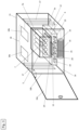
- the charging device 13 serves to charge the accumulator 4a, 4b with electrical energy and is connected to the diagnostic device 12, see in particular Figure 3 . Through the connection to the diagnostic device 12, the charging device 13 can conduct electrical energy to the accumulator 4a, 4b via the interface 24. Electrical energy can also be drawn from the accumulator 4a, 4b with the aid of the charging device 13.
- the cooling device 14 serves to cool the accumulator 4a, 4b with the aid of an air flow F and is designed in the present embodiments as a fan 14a with a fan wheel 14b.
- a fan 14a is positioned next to a side wall of the chamber 11, which has ventilation openings 17. If, as in Figure 2 As indicated, the cooling device 14 designed as a fan 14a generates an air flow F, this can be passed through the ventilation openings 17 at a first side wall into the chamber 11 and flow along the accumulator 4a, 4b and flow out of the chamber 11 again through the ventilation openings 17 on a second side wall.
- the heating device 15 serves to heat the accumulator 4a, 4b.
- the heating device 15 is designed in the form of a heating coil. It is possible for the heating device 15 to consist of more than a single heating coil. As shown in the figures, the heating device 15 designed as a heating coil is mounted in the bottom of the chamber 11 or below an accumulator 4a, 4b positioned in the chamber 11. Alternatively or additionally, a heating device 15 designed as a heating coil can be positioned in the lid and/or on a side wall of the chamber 11.
- Figure 4 shows a system 1 according to the invention according to a second embodiment with a first, second and third receiving device 2a, 2b, 2c and a control unit 3.
- the system 1 according to the second embodiment contains a third receiving device 2c, an acceptance device 25, a storage device 26, a first and second transport device 27a, 27b.
- the third receiving device 2c is substantially identical in construction to the first and/or second receiving device 2a, 2b in the first embodiment.
- the acceptance device 25 serves to receive or accept a first, second or third accumulator 4a, 4b, 4c and according to the second embodiment is essentially designed as a plate or platform.
- the main function of the acceptance device 25 is to create a safe storage option for an accumulator 4a, 4b, 4c, from which the accumulator 4a, 4b, 4c can be transported further.
- the first transport device 27a is designed as a conveyor belt in the second embodiment and is arranged between the acceptance device 25 and the receiving devices 2a, 2b, 2c so that an accumulator 4a, 4b, 4c can be transported from the acceptance device 25 to a receiving device 2a, 2b, 2c.
- the first transport device 27a can also be designed as a roller conveyor with a drive for the rollers.
- the storage device 26 serves, similarly to the acceptance device 25, to receive or accept a battery 4a, 4b, 4c and is designed according to the second embodiment essentially as a plate or platform.
- the essential function of the storage device 26 is a safe storage option for a battery 4a, 4b, 4c from which the accumulator 4a, 4b, 4c can be transported further.
- the second transport device 27b is also designed as a conveyor belt in the second embodiment and is arranged between the receiving devices 2a, 2b, 2c and the storage device 26 such that an accumulator 4a, 4b, 4c can be transported from a receiving device 2a, 2b, 2c to the storage device 26.
- the second transport device 27b can also be designed as a roller conveyor with its own drive for the rollers. Furthermore, the rollers of the second transport device 27b can also be driven by the drive of the first transport device 27a.
- a rechargeable battery 4a, 4b, 4c is positioned in the first receiving device 2a.
- the rechargeable battery 4a, 4b, 4c is connected to the interface 24 of the diagnostic device 12 using the rechargeable battery interface.
- the rechargeable battery 4a, 4b, 4c transmits the capacity values, the voltage value and the temperature value to the diagnostic device 12.
- the rechargeable battery 4a, 4b, 4c contains a temperature sensor 21 and records the temperature of the energy storage cells 5a. If the diagnostic device 12 determines, based on the detected and transmitted temperature value, that this temperature value is below a first predetermined threshold value, the heating device 15 is activated to heat the accumulator 4a, 4b, 4c.
- control device 6 of the accumulator 4a, 4b, 4c can determine, based on the temperature value detected by the temperature sensor 21 of the accumulator 4a, 4b, 4c, that this temperature value is below a first predetermined threshold value.
- the control device 6 of the accumulator 4a, 4b, 4c sends a corresponding signal to the control unit 3 of the system 1 so that the heating device 15 heats the accumulator 4a, 4b, 4c.
- the first temperature threshold is set specifically for the respective accumulator 4a, 4b, 4c and is stored in the memory 10 of the control unit 3 of the system 1.
- the first temperature threshold is set as a temperature value that is too low for an approximately optimal charging of the accumulator 4a, 4b, 4c with electrical energy.
- the first temperature threshold is 5°C.
- the first temperature threshold can also be higher or lower than 5°C.
- the temperature of the accumulator 4a, 4b, 4c is above the first temperature threshold (i.e. higher than 5°C) with the help of the heating device 15, this is detected by the temperature sensor 21 of the accumulator 4a, 4b, 4c and a corresponding signal is transmitted to the control unit 3.
- the accumulator 4a, 4b, 4c has a temperature above the first temperature threshold, which is better suited for a charging process with electrical energy, the actual charging process can start with the help of the charging device 13, so that electrical energy can reach the accumulator 4a, 4b, 4c from the control unit 3.
- the detection device 19 for the electrical voltage of the accumulator 4a, 4b, 4c detects or determines the voltage value of the energy storage cells 5a.
- a corresponding signal is sent from the control device 6 of the accumulator 4a, 4b, 4c to the control unit 3 of the system 1.
- the control unit 3 of the system 1 After receiving the signal, the control unit 3 of the system 1 sends electrical energy to the energy storage cells 5a.
- the desired voltage value (i.e. volts) for the charging process is transmitted from the accumulator 4a, 4b, 4c to the control unit 3 of the system 1 by the corresponding signal.
- a suitable or desired current value i.e. amperes
- the detection device 19 for the electrical voltage of the accumulator 4a, 4b, 4c detects the current voltage value of the energy storage cells 5a.
- the detection device for the electrical current 23 also detects the current (i.e. A or Ah) of the electrical energy transmitted for the charging process during the charging process. After reaching a predetermined voltage value for the energy storage cells 5a, i.e. for example 70 or 80% of the maximum voltage value or capacity of the accumulator 4a, 4b, 4c, the charging process is stopped.
- the cooling device 14 to cool the accumulator 4a, 4b, 4c in order to cool the accumulator 4a, 4b, 4c or the energy storage cells 5a to a temperature value that is below a second temperature threshold value.
- the second temperature threshold value is 60°C according to the exemplary embodiment.
- the second temperature threshold can also be higher or lower than 60°C.
- the heating device 15 to heat the accumulator 4a, 4b, 4c in order to heat the accumulator 4a, 4b, 4c or the energy storage cells 5a to a temperature value that is above a first temperature threshold.
- an accumulator 4a, 4b, 4c is positioned in the first receiving device 2a.
- An accumulator 4a, 4b, 4c is positioned on the receiving device 25.
- the control unit 3 of the system 1 determines which receiving device 2a, 2b, 2c is available, i.e. in which receiving device 2a, 2b, 2c there is currently no accumulator 4a, 4b, 4c. If the accumulator 4a, 4b, 4c is to be transported to the second receiving device 2b, the first transport device 27a transports the accumulator 4a, 4b, 4c from the receiving device 25 to the second receiving device 2b. When the accumulator 4a, 4b, 4c has arrived in the second receiving device 2b, the battery interface connects to the interface 24 of the diagnostic device 12.
- the charging process controlled by the accumulator 4a, 4b, 4c is carried out.
- the cooling device 14 and heating device 15, which are also controlled or regulated by the control device 6 of the accumulator 4a, 4b, 4c, are activated when the corresponding temperature threshold values are reached.
- the accumulator 4a, 4b, 4c is transported from the second receiving device 2b to the storage device 26 by means of the second transport device.
- the accumulator 4a, 4b, 4c charged with electrical energy can be removed from the storage device 26 by a user.
Landscapes
- Engineering & Computer Science (AREA)
- Chemical & Material Sciences (AREA)
- Chemical Kinetics & Catalysis (AREA)
- Electrochemistry (AREA)
- General Chemical & Material Sciences (AREA)
- Manufacturing & Machinery (AREA)
- Power Engineering (AREA)
- Automation & Control Theory (AREA)
- Physics & Mathematics (AREA)
- Electromagnetism (AREA)
- Secondary Cells (AREA)
- Charge And Discharge Circuits For Batteries Or The Like (AREA)
Abstract
System mit wenigstens einer ersten Aufnahmevorrichtung (2a) zum Aufnehmen wenigstens eines ersten Akkumulators (4a), wobei der wenigstens erste Akkumulator einen Temperatursensor (7) zum Erfassen mindestens eines Temperaturwertes des Akkumulators enthält, wobei die wenigstens erste Aufnahmevorrichtung eine Ladeeinrichtung (13) zum Laden des Akkumulators mit elektrischer Energie, eine Kühlungseinrichtung (14) zum Kühlen des Akkumulators sowie eine Wärmeeinrichtung (15) zum Erwärmen des Akkumulators enthält.
Description
- Die vorliegende Erfindung betrifft ein System mit wenigstens einer ersten Aufnahmevorrichtung zum Aufnehmen wenigstens eines ersten Akkumulators, wobei der wenigstens erste Akkumulator einen Temperatursensor zum Erfassen mindestens eines Temperaturwertes des Akkumulators enthält.
- Akkumulatoren (auch Akku genannt) als Energieversorgung für eine Werkzeugmaschine sind gemäß dem Stand der Technik weitgehend bekannt. Diese Akkumulator enthalten für gewöhnlich eine Anzahl an Energiespeicherzellen (auch Akkuzellen genannt), die zum Aufnehmen, Speichern sowie Abgeben von elektrischer Energie dienen und ausgestaltet sind. Das Aufnehmen von elektrischer Energie in die Energiespeicherzellen kann auch als Laden (bzw. Aufladen) bezeichnet werden. Das Abgeben von elektrischer Energie aus den Energiespeicherzellen kann auch als Entladen bezeichnet werden.
- Zum Aufladen bzw. Laden mit elektrischer Energie wird der Akkumulator für gewöhnlich mit einer Ladeeinrichtung (auch Lader oder Charger genannt) verbunden. Die Ladeeinrichtung leitet elektrische Energie gemäß einer vorbestimmten Ladeeinstellung (auch Lademodus genannt) mit festgelegten Parametern für den eigentlichen Ladevorgang an die einzelnen Energiespeicherzellen der Akkumulators.
- Um ein nahezu optimales Laden eines Akkumulators mit elektrischer Energie sowie ein nahezu bestmögliches Entladen des Akkumulators (d.h. die erneute Abgabe der in dem Akkumulator gespeicherten Energie an beispielsweise eine Werkzeugmaschine) zu erreichen, sollten die Parameter des Akkumulators zwischen minimalen und maximalen Schwellwerten befinden. Ein Betreiben, d.h. das Laden und auch Entladen, eines Akkumulators außerhalb der Schwellwerte kann dabei zu wesentlich längeren Ladezeiten, einer geringeren Kapazität und/oder einem niedrigeren Entladestromwert führen.
- Das Einhalten der Parameter des Akkumulators im Idealbereich bzw. zwischen den Schwellwerten ist insbesondere bei dem Außeneinsatz der Akkumulatoren und bei extremen Wetterverhältnissen nur schwer zu ermöglichen.
- Aufgabe der vorliegenden Erfindung ist das vorstehend beschriebene Problem zu lösen.
- Die Aufgabe wird ebenfalls gelöst durch den Gegenstand des Anspruchs 1. Weitere vorteilhafte Ausführungen der Erfindung sind in den entsprechenden Unteransprüchen beschrieben.
- Die Aufgabe wird insbesondere gelöst durch ein System mit wenigstens einer ersten Aufnahmevorrichtung zum Aufnehmen wenigstens eines ersten Akkumulators, wobei der wenigstens erste Akkumulator einen Temperatursensor zum Erfassen mindestens eines Temperaturwertes des Akkumulators enthält.
- Erfindungsgemäß ist vorgesehen, dass die wenigstens erste Aufnahmevorrichtung eine Ladeeinrichtung zum Laden des Akkumulators mit elektrischer Energie, eine Kühlungseinrichtung zum Kühlen des Akkumulators sowie eine Wärmeeinrichtung zum Erwärmen des Akkumulators enthält.
- Zum Speichern von elektrischer Energie enthält der Akkumulator wenigstens eine Energiespeicherzelle. Es ist zu beachten, dass der Temperatursensor des Akkumulators insbesondere, aber nicht ausschließlich dazu ausgestaltet ist, die Temperatur der wenigstens einen Energiespeicherzelle zu erfassen. Bei einer Ausführungsform, bei der der Akkumulator eine Vielzahl an Energiespeicherzellen enthält, ist der Temperatursensor so ausgestaltet und positioniert, dass wenigstens die Temperatur der Energiespeicherzelle erfasst, die von einer Außenwand des Akkumulators am weitesten entfernt angeordnet ist.
- Gemäß einem weiteren vorteilhaften Ausführungsbeispiel kann es möglich sein, dass eine Diagnoseeinrichtung zum Ermitteln wenigstens eines Parameters des Akkumulators enthalten ist. Bei den Parametern des Akkumulators kann es sich um die elektrische Spannung, die Kapazität, die Temperatur, den elektrischen Widerstand und dergleichen handeln.
- Entsprechend einem vorteilhaften Ausführungsbeispiel kann es möglich sein, dass an der wenigstens ersten Aufnahmevorrichtung mindestens eine Anzeigeeinrichtung zum Ausgeben wenigstens eines Freigabesignals oder eines Sperrsignals enthalten ist. Die Anzeigeeinrichtung kann dabei ausgestaltet sein, akustische und/oder visuelle Signale auszugeben. Einem Anwender des Systems kann mit Hilfe der Anzeigeeinrichtung Informationen über den Zustand des Systems und/oder eines Akkumulators gegeben werden.
- Gemäß einem weiteren vorteilhaften Ausführungsbeispiel kann es möglich sein, dass die Aufnahmevorrichtung als Kammer ausgestaltet ist, wobei die Kammer mindestens ein Volumen zum Aufnehmen wenigstens eines Akkumulators und wenigstens eine wiederverschließbare Öffnung zum Platzieren des wenigstens einen Akkumulators im Inneren der Kammer aufweist. Mit Hilfe der Kammer bzw. der Isolierenden Wirkung der Kammer kann eine angestrebte Temperatur für einen in der Kammer positionierten Akkumulator leichter erreicht und gehalten werden.
- Entsprechend einem vorteilhaften Ausführungsbeispiel kann es möglich sein, dass wenigstens eine zweite Aufnahmevorrichtung zur Aufnehmen wenigstens eines zweiten Akkumulators enthalten ist. Hierdurch können gleichzeitig mehrere Akkumulatoren in dem System positioniert werden.
- Gemäß einem weiteren vorteilhaften Ausführungsbeispiel kann es möglich sein, dass eine Annahmeeinrichtung sowie eine erste Transporteinrichtung enthalten ist, wobei die Annahmeeinrichtung zum Empfangen wenigstens eines Akkumulators und die erste Transporteinrichtung zum Transport des wenigstens einen Akkumulators zu einer Aufnahmevorrichtung ausgestaltet ist.
- Entsprechend einem vorteilhaften Ausführungsbeispiel kann es möglich sein, dass eine Lagereinrichtung sowie eine zweite Transporteinrichtung enthalten ist, wobei die Lagereinrichtung zum wenigstens zeitweiligen Lagern wenigstens eines Akkumulators und die zweite Transporteinrichtung zum Transport des wenigstens einen Akkumulators von einer Aufnahmevorrichtung zu der Lagereinrichtung ausgestaltet ist.
- Weitere Vorteile ergeben sich aus der folgenden Figurenbeschreibung. In der Figur ist ein besonders bevorzugtes Ausführungsbeispiel der vorliegenden Erfindung dargestellt. Die Figuren, die Beschreibung und die Ansprüche enthalten zahlreiche Merkmale in Kombination. Der Fachmann wird die Merkmale zweckmäßigerweise auch einzeln betrachten und zu sinnvollen weiteren Kombinationen zusammenfassen.
- In der Figur sind gleiche und gleichartige Komponenten mit gleichen Bezugszeichen beziffert.
- Es zeigt:
- Figur 1
- eine perspektivische Ansicht auf ein System mit einer ersten und zweiten Aufnahmevorrichtung gemäß einem ersten Ausführungsbeispiel;
- Figur 2
- eine perspektivische Ansicht auf das System mit der ersten und zweiten Aufnahmevorrichtung gemäß dem ersten Ausführungsbeispiel in einem aktivierten Zustand;
- Figur 3
- eine perspektivische Ansicht auf eine Aufnahmevorrichtung gemäß einem ersten Ausführungsbeispiel; und
- Figur 4
- perspektivische Ansicht auf ein System mit einer ersten, zweiten und dritten Aufnahmevorrichtung gemäß einem zweiten Ausführungsbeispiel.
-
Figur 1 und2 zeigt ein erfindungsgemäßes System 1 mit einer ersten Aufnahmevorrichtung 2a und zweiten Aufnahmevorrichtung 2b sowie einer Steuereinheit 3 gemäß einem ersten Ausführungsbeispiel. - In der ersten Aufnahmevorrichtung 2a ist ein erster Akkumulator 4a und in der zweiten Aufnahmevorrichtung 2b ist ein zweiter Akkumulator 4b positioniert.
- Die beiden Akkumulatoren 4a, 4b sind in dem ersten Ausführungsbeispiel baugleich. Es ist jedoch auch möglich, dass die Akkumulatoren 4a, 4b nicht baugleich bzw. unterschiedlich ausgestaltet sind.
- Der Akkumulator 4a, 4b kann mit einer Werkzeugmaschine wiederlösbar verbunden werden, um die Werkzeugmaschine mit elektrischer Energie zu versorgen. Die Werkzeugmaschine ist in den Figuren nicht dargestellt.
- Des Weiteren enthält der Akkumulator 4a, 4b im Wesentlichen ein Akku-Gehäuse 5, eine Anzahl an Energiespeicherzellen 5a, eine Akku-Schnittstelle sowie eine Steuerungseinrichtung 6.
- Die Energiespeicherzellen 5a können auch als Akku-Zellen bezeichnet werden und sind im Inneren des Akku-Gehäuses 5 angeordnet. Die Akku-Schnittstelle ist in den Figuren nicht gezeigt.
- Das Akku-Gehäuse 5 enthält dabei im Wesentlichen ein Deckelelement, vier Seitenwände und ein Bodenelement.
- Die Akku-Schnittstelle ist an der Außenseite des Deckelelements angeordnet und dient zum elektrischen bzw. elektronischen sowie mechanischen Verbinden des Akkumulators 4a, 4b mit der Werkzeugmaschine oder der Aufnahmevorrichtung 2a, 2b.
- Zum elektrischen bzw. elektronischen Verbinden weist die Akku-Schnittstelle einen Pluskontakt, einen Minuskontakt und einen Kommunikationskontakt auf. Der Plus- und Minuskontakt dient zur Erzeugen eines Stromkreises, wenn der Akkumulator 4a, 4b mit einer Werkzeugmaschine oder der Aufnahmevorrichtung 2a, 2b verbunden ist. Der Kommunikationskontakt dient zum Senden und Empfangen von Daten sowie Informationen in Form von elektrischen Signalen. Alternativ oder zusätzlich kann der Akkumulator 4a, 4b auch eine Funkkommunikation (z.B. Bluetooth) bzw. drahtlose Kommunikation enthalten.
- Die Energiespeicherzellen 5a dienen zum Aufnehmen, Speichern und erneuten Abgeben elektrischer Energie. Wie in den Figuren angedeutet, sind die Energiespeicherzellen 5a in zylindrischer Form und auf Basis einer Lithium-Ionen-Technologie ausgestaltet. Jede Energiespeicherzelle 5a enthält an einem Ende eine Kontakteinrichtung, die zur Übertragung elektrischer Energie dient. Die einzelnen Kontakteinrichtung sind über entsprechende Leitungen mit der Steuerungseinrichtung 6 verbunden.
- Alternativ können die Energiespeicherzellen 5a auch auf einer anderen geeigneten Technologie basieren.
- Die Kontakteinrichtung sind in den Figuren nicht gezeigt.
- Die zylindrische Form der Energiespeicherzellen 5a ist ebenfalls beispielhaft, sodass auch jede andere geeignete Form bzw. Geometrie gewählt werden kann. So ist es insbesondere auch möglich, dass die Energiespeicherzellen 5a als Pouchzellen ausgestaltet sind.
- Es ist zudem auch möglich, dass der Akkumulator 4a, 4b sowohl zylindrische Energiespeicherzellen 5a als auch Pouch-Zellen enthält. Es ist insbesondere möglich, dass der Akkumulator 4a, 4b eine einzige zylindrische Energiespeicherzelle 5a und eine einzige Pouchzelle enthält.
- Die Steuerungseinrichtung 6 regelt und steuert verschiedene Funktionen des Akkumulators 4a, 4b. Des Weiteren enthält die Steuerungseinrichtung 6 einen Temperatursensor 7 zum Erfassen mindestens eines Temperaturwertes des Akkumulators 4a, 4b. Wie in den Figuren angedeutet, ist der Temperatursensor 7 in der Mitte des Akkumulators 4a, 4b, d.h. in der Nähe der Energiespeicherzelle 5a positioniert, die von den Wänden des Akku-Gehäuses 5 am weitest entfernt ist. Für gewöhnlich wird diese Energiespeicherzelle 5a während der Verwendung des Akkumulators 4a, 4b am wärmsten und ist dadurch am ehesten anfällig für wärmebedingte Beschädigungen.
- Darüber hinaus ist die Steuerungseinrichtung 6 so mit den Energiespeicherzellen 5a und der Akku-Schnittstelle über entsprechende Leitungen verbunden, dass elektrische Energie von den Energiespeicherzellen 5a über die Steuerungseinrichtung 6 zu der Akku-Schnittstelle gelangen kann.
- Zum wiederlösbaren mechanischen Koppeln des Akkumulators 4a, 4b mit der Werkzeugmaschine ist eine Schienenvorrichtung vorgesehen.
- Eine (in den Figuren nicht gezeigte) Verriegelungsvorrichtung dient zum wiederlösbaren Verbinden des Akkumulators 4a, 4b mit der Werkzeugmaschine oder der Aufnahmevorrichtung 2a, 2b.
- Die Steuereinheit 3 des Systems 1 dient zum Regeln und Steuern der einzelnen Funktionen des Systems 1 und insbesondere der Funktionen der Aufnahmevorrichtung 2a, 2b. Des Weiteren enthält die Steuereinheit 3 ein Ein- und Ausgabeeinrichtung 8, einen Netzanschluss 9 sowie einen Speicher 10.
- Wie in den
Figuren 1 ,2 und4 angedeutet ist der Netzanschluss 9 in Form eines Stromkabel ausgestaltet, um das System 1 wiederlösbar mit einer Netzstromquelle (z.B. Steckdose) zur Versorgung mit elektrischer Energie zu verbinden. Die Netzstromquelle ist in den Figuren nicht gezeigt. - Die erste und zweite Aufnahmevorrichtung 2a, 2b sind gemäß dem ersten Ausführungsbeispiel im Wesentlichen baugleich ausgestaltet.
- Jede Aufnahmevorrichtung 2a, 2b enthält dabei eine Kammer 11, eine Diagnoseeinrichtung 12, eine Ladeeinrichtung 13, eine Kühlungseinrichtung 14 und eine Wärmeeinrichtung 15.
- Wie in
Figur 1 angedeutet, enthält das System 1 gemäß dem ersten Ausführungsbeispiel einen Rahmen R. In dem Rahmen R sind die beiden Aufnahmevorrichtungen 2a, 2b sowie die Steuereinheit 3 positioniert. Wie ebenfalls inFigur 1 angedeutet ist an einer Seite des Rahmens R die Kühlungseinrichtung 14 für die erste Aufnahmevorrichtung 2a und an einer anderen Seite die Kühlungseinrichtung 14 für die zweite Aufnahmevorrichtung 2b positioniert. Anstelle eines Rahmens R kann auch ein geschlossener oder nahezu geschlossener Kasten vorgesehen sein. - Wie den Figuren entnehmbar weist die Kammer 11 im Wesentlichen einen Boden, einen Deckel, drei Seitenwände und eine Öffnung 16 auf. Die Kammer 11 weist ein Volumen (oder Innenraum) zum Aufnehmen eines Akkumulators 2a, 2b auf.
- Die Öffnung 16 ist in Form einer Tür 16a mit einem Scharnier 16b ausgestaltet, sodass die Kammer 11 verschlossen werden kann. Des Weiteren ist die Öffnung 16 mindestens so groß, dass ein Akkumulator 2a, 2b hindurch passt. Entsprechend einem weiteren Ausführungsbeispiel weist die Kammer 11 keine Tür auf, sodass die Kammer 11 zu einer Seite hin stets geöffnet ist.
- Darüber hinaus enthalten zwei gegenüberliegende Seitenwände längliche Lüftungsöffnungen 17 auf. Alternativ oder zusätzlich kann auch der Deckel wenigstens eine Lüftungsöffnung 17 enthalten.
- Die Lüftungsöffnungen 17 dienen dazu, dass das Kühlluft in das Innere der Kammer 11 und wieder aus der Kammer 11 hinausströmen kann.
- Ferner ist, wie in den Figuren angedeutet, an einer Außenseite des Deckels der Kammer 11 eine Anzeigeeinrichtung 18 zum Ausgeben wenigstens eines Freigabesignals oder eines Sperrsignals positioniert. Die Anzeigeeinrichtung 18 ist dabei ausgestaltet, dass akustische und/oder visuelle Signale ausgegeben werden können. Es ist zudem möglich, dass weitere Signale, neben einem Freigabesignal oder Sperrsignal, ausgesendet werden können. In dem vorliegenden Ausführungsbeispiel ist die Anzeigeeinrichtung 18 in Form einer ersten und zweiten LED-Leuchte 18a, 18b ausgestaltet, wobei eine grüne LED-Leuchte 18a das Freigabesignal anzeigt und eine rote LED-Leuchte 18b das Sperrsignal anzeigt.
- Die Diagnoseeinrichtung 12 dient zum Ermitteln wenigstens eines Parameters des Akkumulators 4a, 4b und ist mit der Steuereinheit 3 sowie dem Speicher 10 des Systems 1 so verbunden, dass Daten und Informationen in Form von Signalen ausgetauscht werden können.
- Bei den Parameter handelt es sich um die elektrische Spannung, die Kapazität, die Temperatur, den elektrischen Widerstand und dergleichen. Wie in
Figur 3 angedeutet, enthält die Diagnoseeinrichtung 12 daher eine Erfassungseinrichtung für die elektrische Spannung 19, eine Erfassungseinrichtung für die elektrische Kapazität 20, einen Temperatursensor zum Erfassen von Temperaturwerten 21, eine Erfassungseinrichtung für den elektrischen Widerstand 22 und eine Erfassungseinrichtung für die elektrische Stromstärke 23. - Die Diagnoseeinrichtung 12 enthält eine Schnittstelle 24, mit dessen Hilfe der Akkumulator 4a, 4b wiederlösbar mit der Diagnoseeinrichtung 12 verbunden werden kann. Die Schnittstelle 24 enthält dabei im Wesentlichen einen Pluskontakt, einen Minuskontakt und einen Kommunikationskontakt. Wenn der Akkumulator 4a, 4b mit der Diagnoseeinrichtung 12 in Kontakt treten soll, stehen der Kommunikationskontakt der Diagnoseeinrichtung 12 und der Kommunikationskontakt der Akku-Schnittstelle miteinander so in Verbindung, dass Daten und Informationen in Form von Signalen ausgetauscht werden können. Auf diese Weise werden bei einer Verbindung die Parameter des Akkumulators 4a, 4b an die Diagnoseeinrichtung 12 übertragen. In dem alternativen Ausführungsbeispiel können die Parameter des Akkumulators 4a, 4b auch drahtlos bzw. per Funk von dem Akkumulator 4a, 4b zu der Diagnoseeinrichtung 12 übertragen werden.
- Die Ladeeinrichtung 13 dient zum Laden des Akkumulators 4a, 4b mit elektrischer Energie und steht mit der Diagnoseeinrichtung 12 in Verbindung, vgl. insbesondere
Figur 3 . Durch die Verbindung mit der Diagnoseeinrichtung 12 kann die Ladeeinrichtung 13 elektrische Energie über die Schnittstelle 24 zu dem Akkumulator 4a, 4b leiten. Ebenso kann auch von dem Akkumulator 4a, 4b elektrische Energie mit Hilfe der Ladeeinrichtung 13 entnommen. - Die Kühlungseinrichtung 14 dient zum Kühlen des Akkumulators 4a, 4b mit Hilfe einer Luftströmung F und ist in den vorliegenden Ausführungsbeispielen als Lüfter 14a mit einem Lüfterrad 14b ausgestaltet. In dem vorliegenden Ausführungsbeispiel ist jeweils ein Lüfter 14a neben einer Seitenwand der Kammer 11 positioniert, die Lüftungsöffnungen 17 aufweist. Wenn, wie in
Figur 2 angedeutet, die als Lüfter 14a ausgestaltete Kühlungseinrichtung 14 eine Luftströmung F erzeugt, kann dieser durch die Lüftungsöffnungen 17 an einer ersten Seitenwand in die Kammer 11 einströmen über sowie an dem Akkumulator 4a, 4b entlangströmen und durch die Lüftungsöffnungen 17 an einer zweiten Seitenwand aus der Kammer 11 wieder hinausströmen. - Die Wärmeeinrichtung 15 dient zum Erwärmen des Akkumulators 4a, 4b. In dem vorliegenden Ausführungsbeispiel ist die Wärmeeinrichtung 15 in Form einer Heizspule ausgestaltet. Es ist möglich, dass die Wärmeeinrichtung 15 aus mehr als einer einzigen Heizspule besteht. Wie in den Figuren gezeigt, ist die als Heizspule ausgestaltete Wärmeeinrichtung 15 in dem Boden der Kammer 11 bzw. unterhalb eines in der Kammer 11 positionierten Akkumulators 4a, 4b angebracht. Alternativ oder zusätzlich kann eine als Heizspule ausgestaltete Wärmeeinrichtung 15 in dem Deckel und/oder an einer Seitenwand der Kammer 11 positioniert sein.
-
Figur 4 zeigt ein erfindungsgemäßes System 1 gemäß einem zweiten Ausführungsbeispiel mit einer ersten, zweiten und dritten Aufnahmevorrichtung 2a, 2b, 2c sowie eine Steuereinheit 3. Im Unterschied zu dem ersten Ausführungsbeispiel enthält das System 1 gemäß dem zweiten Ausführungsbeispiel eine dritte Aufnahmevorrichtung 2c, eine Annahmeeinrichtung 25, eine Lagereinrichtung 26, eine erste und zweite Transporteinrichtung 27a, 27b. - Die dritte Aufnahmevorrichtung 2c ist im Wesentlichen baugleich mit der ersten und/oder zweiten Aufnahmevorrichtung 2a, 2b in dem ersten Ausführungsbeispiel.
- Die Annahmeeinrichtung 25 dient zum Empfangen bzw. Annehmen eines ersten, zweiten oder drittem Akkumulators 4a, 4b, 4c und ist gemäß dem zweiten Ausführungsbeispiel im Wesentlichen als Platte oder Plattform ausgestaltet. Die wesentliche Funktion der Annahmeeinrichtung 25 ist dabei eine sichere Ablagemöglichkeit für einen Akkumulator 4a, 4b, 4c zu schaffen, von dem aus der Akkumulator 4a, 4b, 4c weitergeführt werden kann. Die erste Transporteinrichtung 27a ist in dem zweiten Ausführungsbeispiel als Förderband ausgestaltet und so zwischen der Annahmeeinrichtung 25 und den Aufnahmevorrichtungen 2a, 2b, 2c angeordnet, dass ein Akkumulator 4a, 4b, 4c von der Annahmeeinrichtung 25 zu einer Aufnahmevorrichtung 2a, 2b, 2c transportiert werden kann.
- Alternativ kann die erste Transporteinrichtung 27a auch als Rollenförderer mit einem Antrieb für die Rollen ausgestaltet sein.
- Die Lagereinrichtung 26 dient, ähnlich wie die Annahmeeinrichtung 25, zum Empfangen bzw. Annehmen eines Akkumulators 4a, 4b, 4c und ist gemäß dem zweiten Ausführungsbeispiel im Wesentlichen als Platte oder Plattform ausgestaltet. Die wesentliche Funktion der Lagereinrichtung 26 ist dabei eine sichere Ablagemöglichkeit für einen Akkumulator 4a, 4b, 4c zu schaffen, von dem aus der Akkumulator 4a, 4b, 4c weitergeführt werden kann. Die zweite Transporteinrichtung 27b ist in dem zweiten Ausführungsbeispiel ebenfalls als Förderband ausgestaltet und so zwischen der Aufnahmevorrichtungen 2a, 2b, 2c und der Lagereinrichtung 26 angeordnet, dass ein Akkumulator 4a, 4b, 4c von einer Aufnahmevorrichtung 2a, 2b, 2c zu der Lagereinrichtung 26 transportiert werden kann.
- Alternativ kann auch die zweite Transporteinrichtung 27b auch als Rollenförderer mit einem eigenen Antrieb für die Rollen ausgestaltet sein. Des Weiteren können die Rollen der zweiten Transporteinrichtung 27b auch durch den Antrieb der ersten Transporteinrichtung 27a angetrieben werden.
- Zum Betreiben des erfindungsgemäßem Systems 1 gemäß dem ersten Ausführungsbeispiel wird ein Akkumulator 4a, 4b, 4c in die erste Aufnahmevorrichtung 2a positioniert. Der Akkumulator 4a, 4b, 4c wird mit Hilfe der Akku-Schnittstelle mit der Schnittstelle 24 der Diagnoseeinrichtung 12 verbunden. Durch die Verbindung des Akkumulators 4a, 4b, 4c mit der Diagnoseeinrichtung 12 können Daten und Informationen zwischen dem Akkumulator 4a, 4b, 4c und der Diagnoseeinrichtung 12 ausgetauscht werden. Der Akkumulator 4a, 4b, 4c überträgt dabei die Kapazitätswerte, den Spannungswert und den Temperaturwert an die Diagnoseeinrichtung 12. Der Akkumulator 4a, 4b, 4c enthält dabei einen Temperatursensor 21 und erfasst die Temperatur der Energiespeicherzellen 5a. Wenn die Diagnoseeinrichtung 12 anhand des erfassten und übermittelten Temperaturwerts ermittelt, dass dieser Temperaturwert unterhalb eines ersten vorbestimmten Schwellwert liegt, wird die Wärmeeinrichtung 15 zum Erwärmen des Akkumulators 4a, 4b, 4c aktiviert.
- Alternativ oder zusätzlich hierzu kann die Steuerungseinrichtung 6 des Akkumulators 4a, 4b, 4c anhand des von dem Temperatursensor 21 des Akkumulators 4a, 4b, 4c erfassten Temperaturwertes ermitteln, dass dieser Temperaturwert unterhalb eines ersten vorbestimmten Schwellwert liegt. Die Steuerungseinrichtung 6 des Akkumulators 4a, 4b, 4c sendet ein entsprechendes Signal an die Steuereinheit 3 des Systems 1, damit die Wärmeeinrichtung 15 den Akkumulator 4a, 4b, 4c erwärmt.
- Der erste Temperaturschwellwert ist spezifisch für den jeweiligen Akkumulator 4a, 4b, 4c festgelegt und in dem Speicher 10 der Steuereinheit 3 des Systems 1 hinterlegt. Der erste Temperaturschwellwert ist als Temperaturwert festgelegt, der für eine annähernd optimale Ladung des Akkumulators 4a, 4b, 4c mit elektrischer Energie zu niedrig ist. So ist beispielsweise möglich, dass der erste Temperaturschwellwert 5°C beträgt. Alternativ kann der erste Temperaturschwellwert auch höher oder niedriger als 5°C sein.
- Wenn mit Hilfe der Wärmeeinrichtung 15 die Temperatur des Akkumulators 4a, 4b, 4c über dem ersten Temperaturschwellwert (d.h. höher als 5°C) liegt, wird dies von dem Temperatursensor 21 des Akkumulators 4a, 4b, 4c erfasst und ein entsprechendes Signal an die Steuereinheit 3 übermittelt. Nachdem nun der Akkumulator 4a, 4b, 4c eine Temperatur über dem ersten Temperaturschwellwert aufweist, die besser für einen Ladevorgang mit elektrischer Energie geeignet ist, kann mit Hilfe der Ladeeinrichtung 13 der tatsächliche Ladevorgang starten, sodass von der Steuereinheit 3 elektrische Energie zu dem Akkumulator 4a, 4b, 4c gelangen kann.
- Die Erfassungseinrichtung 19 für die elektrische Spannung des Akkumulators 4a, 4b, 4c erfasst bzw. ermittelt den Spannungswert der Energiespeicherzellen 5a. Zum Laden der Energiespeicherzellen 5a mit elektrischer Energie wird ein entsprechendes Signal von der Steuerungseinrichtung 6 des Akkumulators 4a, 4b, 4c zu der Steuereinheit 3 des Systems 1 gesendet. Die Steuereinheit 3 des Systems 1 sendet nach Empfang des Signals elektrische Energie zu den Energiespeicherzellen 5a. Der gewünschte Spannungswert (d.h. Volt) für den Ladevorgang wird dabei von dem Akkumulator 4a, 4b, 4c durch das entsprechende Signal an die Steuereinheit 3 des Systems 1 übermittelt. Darüber hinaus wird mit Hilfe des ausgesendeten Signals von dem Akkumulator 4a, 4b, 4c an das System 1 auch ein geeigneter bzw. gewünschter Stromstärkewert (d.h. Amper) übermittelt und hierdurch von dem Akkumulator 4a, 4b, 4c für den Ladevorgang vorgegeben.
- Während des Ladens erfasst die Erfassungseinrichtung 19 für die elektrische Spannung des Akkumulators 4a, 4b, 4c den aktuellen Spannungswert der Energiespeicherzellen 5a. Neben der Erfassungseinrichtung 19 für die elektrische Stromstärke erfasst auch die Erfassungseinrichtung für die elektrische Stromstärke 23 die Stromstärke (d.h. A bzw. Ah) der für den Ladevorgang übermittelten elektrischen Energie während des Ladevorgangs. Nach Erreichen eines vorbestimmten Spannungswert für die Energiespeicherzellen 5a, d.h. beispielsweise 70 oder 80% des maximalen Spannungswerts bzw. Kapazität des Akkumulators 4a, 4b, 4c, wird der Ladevorgang gestoppt.
- Es ist während des Ladevorgangs möglich, dass die Kühlungseinrichtung 14 den Akkumulator 4a, 4b, 4c kühlt, um den Akkumulator 4a, 4b, 4c bzw. die Energiespeicherzellen 5a auf einen Temperaturwert zu kühlen, der unterhalb eines zweiten Temperaturschwellwert liegt. Der zweite Temperaturschwellwert beträgt gemäß dem Ausführungsbeispiel 60°C.
- Alternativ kann der zweite Temperaturschwellwert auch höher oder niedriger als 60°C sein. Darüber hinaus ist es während des Ladevorgangs auch möglich, dass die Wärmeeinrichtung 15 den Akkumulator 4a, 4b, 4c erwärmt, um den Akkumulator 4a, 4b, 4c bzw. die Energiespeicherzellen 5a auf einen Temperaturwert zu erwärmen, der oberhalb eines ersten Temperaturschwellwert liegt.
- Zum Betreiben des erfindungsgemäßem Systems 1 gemäß dem zweiten Ausführungsbeispiel wird ein Akkumulator 4a, 4b, 4c in die erste Aufnahmevorrichtung 2a positioniert.
- Ein Akkumulator 4a, 4b, 4c wird auf die Annahmeeinrichtung 25 positioniert. Die Steuereinheit 3 des Systems 1 ermittelt welche Aufnahmevorrichtung 2a, 2b, 2c verfügbar ist, d.h. in welcher Aufnahmevorrichtung 2a, 2b, 2c sich zurzeit kein Akkumulator 4a, 4b, 4c befindet. Wenn der Akkumulator 4a, 4b, 4c in die zweite Aufnahmevorrichtung 2b transportiert werden soll, befördert die erste Transporteinrichtung 27a den Akkumulator 4a, 4b, 4c von der Annahmeeinrichtung 25 zu der zweiten Aufnahmevorrichtung 2b. Wenn der Akkumulator 4a, 4b, 4c in der zweiten Aufnahmevorrichtung 2b angelangt ist, verbindet sich die Akku-Schnittstelle mit der Schnittstelle 24 der Diagnoseeinrichtung 12. Nach dem Übermitteln der entsprechenden Daten und Information in Form von Signalen von der Steuerungseinrichtung 6 des Akkumulators 4a, 4b, 4c an die Steuereinheit 3 des Systems 1 wird der von dem Akkumulator 4a, 4b, 4c geregelte Ladevorgang durchgeführt. Die ebenfalls von der Steuerungseinrichtung 6 des Akkumulators 4a, 4b, 4c gesteuerten bzw. geregelten Kühlungseinrichtung 14 und Wärmeeinrichtung 15 werden bei Erreichen der entsprechenden Temperaturschwellwerte aktiviert.
- Nach Beendigung des Ladevorgangs wird der Akkumulator 4a, 4b, 4c mittels der zweiten Transporteinrichtung von der zweiten Aufnahmevorrichtung 2b zu der Lagereinrichtung 26 transportiert. Von der Lagereinrichtung 26 kann der mit elektrischer Energie geladene Akkumulator 4a, 4b, 4c von einem Anwender entnommen werden.
-
- 1
- System
- 2a
- erste Aufnahmevorrichtung
- 2b
- zweite Aufnahmevorrichtung
- 2c
- dritte Aufnahmevorrichtung
- 3
- Steuereinheit
- 4a
- erster Akkumulator
- 4b
- zweiter Akkumulator
- 4c
- dritter Akkumulator
- 5
- Akku-Gehäuse
- 5a
- Energiespeicherzelle
- 6
- Steuerungseinrichtung
- 7
- Temperatursensor
- 8
- Ein- und Ausgabeeinrichtung
- 9
- Netzanschluss
- 10
- Speicher
- 11
- Kammer
- 12
- Diagnoseeinrichtung
- 13
- Ladeeinrichtung
- 14
- Kühlungseinrichtung
- 14a
- Lüfter
- 14b
- Lüfterrad
- 15
- Wärmeeinrichtung
- 16
- Öffnung
- 16a
- Tür
- 16b
- Scharnier
- 17
- Lüftungsöffnung
- 18
- Anzeigeeinrichtung
- 18a
- erste LED-Leuchte
- 18b
- zweite LED-Leuchte
- 19
- Erfassungseinrichtung für die elektrische Spannung
- 20
- Erfassungseinrichtung für die elektrische Kapazität
- 21
- Temperatursensor zum Erfassen von Temperaturwerten
- 22
- Erfassungseinrichtung für den elektrischen Widerstand
- 23
- Erfassungseinrichtung für die elektrische Stromstärke
- 24
- Schnittstelle
- 25
- Annahmeeinrichtung
- 26
- Lagereinrichtung
- 27a
- erste Transporteinrichtung
- 27b
- zweite Transporteinrichtung
- F
- Luftströmung
- R
- Rahmen
Claims (7)
- System (1) mit wenigstens einer ersten Aufnahmevorrichtung (2a, 2b, 2c) zum Aufnehmen wenigstens eines ersten Akkumulators (4a, 4b, 4c), wobei der wenigstens erste Akkumulator (4a, 4b, 4c) einen Temperatursensor (7) zum Erfassen mindestens eines Temperaturwertes des Akkumulators (4a, 4b, 4c) enthält,
dadurch gekennzeichnet, dass die wenigstens erste Aufnahmevorrichtung (2a, 2b, 2c) eine Ladeeinrichtung (13) zum Laden des Akkumulators (4a, 4b, 4c) mit elektrischer Energie, eine Kühlungseinrichtung (14) zum Kühlen des Akkumulators (4a, 4b, 4c) sowie eine Wärmeeinrichtung (15) zum Erwärmen des Akkumulators (4a, 4b, 4c) enthält. - System (1) nach Anspruch 1,
dadurch gekennzeichnet, dass eine Diagnoseeinrichtung (12) zum Ermitteln wenigstens eines Parameters des Akkumulators (4a, 4b, 4c) enthalten ist. - System (1) nach Anspruch 1 oder 2,
dadurch gekennzeichnet, dass an der wenigstens ersten Aufnahmevorrichtung (2a, 2b, 2c) mindestens eine Anzeigeeinrichtung (18) zum Ausgeben wenigstens eines Freigabesignals oder eines Sperrsignals enthalten ist. - System (1) nach wenigstens einem der Ansprüche 1 bis 3,
dadurch gekennzeichnet, dass die Aufnahmevorrichtung (2a, 2b, 2c) als Kammer (11) ausgestaltet ist, wobei die Kammer (11) mindestens ein Volumen zum Aufnehmen wenigstens eines Akkumulators (4a, 4b, 4c) und wenigstens eine wiederverschließbare Öffnung zum Platzieren des wenigstens einen Akkumulators (4a, 4b, 4c) im Inneren der Kammer (11) aufweist. - System (1) nach wenigstens einem der Ansprüche 1 bis 4,
dadurch gekennzeichnet, dass wenigstens eine zweite Aufnahmevorrichtung (2a, 2b, 2c) zur Aufnehmen wenigstens eines zweiten Akkumulators (4a, 4b, 4c) enthalten ist. - System (1) nach wenigstens einem der Ansprüche 1 bis 5,
dadurch gekennzeichnet, dass eine Annahmeeinrichtung (25) sowie eine erste Transporteinrichtung (27a) enthalten ist, wobei die Annahmeeinrichtung (25) zum Empfangen wenigstens eines Akkumulators (4a, 4b, 4c) und die erste Transporteinrichtung (27a) zum Transport des wenigstens einen Akkumulators (4a, 4b, 4c) zu einer Aufnahmevorrichtung (2a, 2b, 2c) ausgestaltet ist. - System (1) nach wenigstens einem der Ansprüche 1 bis 6,
dadurch gekennzeichnet, dass eine Lagereinrichtung (26) sowie eine zweite Transporteinrichtung (27b) enthalten ist, wobei die Lagereinrichtung (26) zum wenigstens zeitweiligen Lagern wenigstens eines Akkumulators (4a, 4b, 4c) und die zweite Transporteinrichtung (27b) zum Transport des wenigstens einen Akkumulators (4a, 4b, 4c) von einer Aufnahmevorrichtung (2a, 2b, 2c) zu der Lagereinrichtung (26) ausgestaltet ist.
Priority Applications (4)
| Application Number | Priority Date | Filing Date | Title |
|---|---|---|---|
| EP23156735.5A EP4418488A1 (de) | 2023-02-15 | 2023-02-15 | System zum laden, kühlen und erwärmen von akkumulatoren |
| CN202480006056.XA CN120419069A (zh) | 2023-02-15 | 2024-01-11 | 用于充电、冷却和加热可充电电池的系统 |
| PCT/EP2024/050533 WO2024170173A1 (de) | 2023-02-15 | 2024-01-11 | System zum laden, kühlen und erwärmen von akkumulatoren |
| EP24700744.6A EP4666363A1 (de) | 2023-02-15 | 2024-01-11 | System zum laden, kühlen und erwärmen von akkumulatoren |
Applications Claiming Priority (1)
| Application Number | Priority Date | Filing Date | Title |
|---|---|---|---|
| EP23156735.5A EP4418488A1 (de) | 2023-02-15 | 2023-02-15 | System zum laden, kühlen und erwärmen von akkumulatoren |
Publications (1)
| Publication Number | Publication Date |
|---|---|
| EP4418488A1 true EP4418488A1 (de) | 2024-08-21 |
Family
ID=85251824
Family Applications (2)
| Application Number | Title | Priority Date | Filing Date |
|---|---|---|---|
| EP23156735.5A Withdrawn EP4418488A1 (de) | 2023-02-15 | 2023-02-15 | System zum laden, kühlen und erwärmen von akkumulatoren |
| EP24700744.6A Pending EP4666363A1 (de) | 2023-02-15 | 2024-01-11 | System zum laden, kühlen und erwärmen von akkumulatoren |
Family Applications After (1)
| Application Number | Title | Priority Date | Filing Date |
|---|---|---|---|
| EP24700744.6A Pending EP4666363A1 (de) | 2023-02-15 | 2024-01-11 | System zum laden, kühlen und erwärmen von akkumulatoren |
Country Status (3)
| Country | Link |
|---|---|
| EP (2) | EP4418488A1 (de) |
| CN (1) | CN120419069A (de) |
| WO (1) | WO2024170173A1 (de) |
Citations (4)
| Publication number | Priority date | Publication date | Assignee | Title |
|---|---|---|---|---|
| WO2009009176A2 (en) * | 2007-04-03 | 2009-01-15 | Lockheed Martin Corporation | Transportable electrical energy storage system |
| CN201860129U (zh) * | 2010-08-10 | 2011-06-08 | 新普科技股份有限公司 | 电动车电池交换系统 |
| WO2013013183A1 (en) * | 2011-07-20 | 2013-01-24 | Milwaukee Electric Tool Corporation | Multi-bay battery charger |
| CN115473299A (zh) * | 2022-04-06 | 2022-12-13 | 北京旷视机器人技术有限公司 | 充电系统及充电方法 |
-
2023
- 2023-02-15 EP EP23156735.5A patent/EP4418488A1/de not_active Withdrawn
-
2024
- 2024-01-11 WO PCT/EP2024/050533 patent/WO2024170173A1/de not_active Ceased
- 2024-01-11 CN CN202480006056.XA patent/CN120419069A/zh active Pending
- 2024-01-11 EP EP24700744.6A patent/EP4666363A1/de active Pending
Patent Citations (4)
| Publication number | Priority date | Publication date | Assignee | Title |
|---|---|---|---|---|
| WO2009009176A2 (en) * | 2007-04-03 | 2009-01-15 | Lockheed Martin Corporation | Transportable electrical energy storage system |
| CN201860129U (zh) * | 2010-08-10 | 2011-06-08 | 新普科技股份有限公司 | 电动车电池交换系统 |
| WO2013013183A1 (en) * | 2011-07-20 | 2013-01-24 | Milwaukee Electric Tool Corporation | Multi-bay battery charger |
| CN115473299A (zh) * | 2022-04-06 | 2022-12-13 | 北京旷视机器人技术有限公司 | 充电系统及充电方法 |
Also Published As
| Publication number | Publication date |
|---|---|
| WO2024170173A1 (de) | 2024-08-22 |
| EP4666363A1 (de) | 2025-12-24 |
| CN120419069A (zh) | 2025-08-01 |
Similar Documents
| Publication | Publication Date | Title |
|---|---|---|
| DE19654045B4 (de) | Verfahren zum Vorhersagen der verbleibenden Kapazität einer Batterieeinheit, Batterieeinheit und Vorrichtung zum Vorhersagen der verbleibenden Kapazität einer Batterieeinheit | |
| DE202019101228U1 (de) | Batteriespeichersystem | |
| DE102012218663A1 (de) | Ladeschale und Verfahren zum Laden von Hörgeräten | |
| WO2008031653A1 (de) | Ladevorrichtung | |
| DE102023119421A1 (de) | Batterieladevorrichtung | |
| DE102007051052A1 (de) | Verfahren zum Laden von wiederaufladbaren Lithium-Akkumulatoren, Ladegerät und Lithium-Akkumulator | |
| DE3734221A1 (de) | Verfahren zur vermeidung einer ueberhitzung von hochtemperatur-speicherbatterien | |
| DE102009035472A1 (de) | Vorrichtung zum Auslesen des Ladezustandes einer Batterie | |
| EP4418488A1 (de) | System zum laden, kühlen und erwärmen von akkumulatoren | |
| WO2023083651A1 (de) | Verfahren zum laden oder entladen eines wechselbaren energiespeichers mittels eines elektrogeräts sowie system mit einem wechselbaren energiespeicher und einem elektrogerät zur durchführung des verfahrens | |
| EP3534453B1 (de) | Akkupack für ein elektrogerät, ladegerät für einen akkupack und verfahren zum betreiben eines akkupacks | |
| DE102012010675A1 (de) | Flurförderzeug mit Batterieeinschubplätzen | |
| DE102010055305B4 (de) | Elektrische Leistungsquelle und Ladebox | |
| DE4236811C1 (de) | Verfahren zum Laden von Akkumulatoren in schnurlosen Kommunikationsendeinrichtungen und Anordnung zur Durchführung des Verfahrens | |
| DE202021004371U1 (de) | Batterieladegerät und damit verwendete Ladedockingstation | |
| EP4137831A1 (de) | Verfahren zum bestimmen des gesundheitszustands eines akkumulators | |
| EP2684271B1 (de) | Energiespeicher und energiespeichersystem | |
| DE102007057552A1 (de) | Ladestation und Verfahren zum Laden von Akkumulatoren sowie Ladesystem mit einer Ladestation und mit wenigstens einem Akkumulator | |
| EP3219536A1 (de) | Modulares system für schnellladefähige traktionsbatterie für flurförderzeug | |
| DE102020212769B4 (de) | Verfahren zum unterbrechungsfreien Betreiben eines netzunabhängig betriebenen mobilen Systems und mobiles System | |
| EP4507156A1 (de) | Adaptive regelung für einen verbund von batterien und werkzeugmaschinen | |
| EP3580806B1 (de) | Akkuvorrichtung | |
| EP4507155A1 (de) | Adaptive regelung für einen verbund von akkumulatoren | |
| EP4507154A1 (de) | Adaptive regelung für batterien | |
| EP4730593A1 (de) | Verfahren zum kontrollierten entladen eines akkumulators auf einen bestimmten ladungswert |
Legal Events
| Date | Code | Title | Description |
|---|---|---|---|
| PUAI | Public reference made under article 153(3) epc to a published international application that has entered the european phase |
Free format text: ORIGINAL CODE: 0009012 |
|
| STAA | Information on the status of an ep patent application or granted ep patent |
Free format text: STATUS: THE APPLICATION HAS BEEN PUBLISHED |
|
| AK | Designated contracting states |
Kind code of ref document: A1 Designated state(s): AL AT BE BG CH CY CZ DE DK EE ES FI FR GB GR HR HU IE IS IT LI LT LU LV MC ME MK MT NL NO PL PT RO RS SE SI SK SM TR |
|
| STAA | Information on the status of an ep patent application or granted ep patent |
Free format text: STATUS: THE APPLICATION IS DEEMED TO BE WITHDRAWN |
|
| 18D | Application deemed to be withdrawn |
Effective date: 20250222 |