EP4418580A2 - Procédé et appareil pour transmettre/recevoir une unité de données de protocole de couche physique - Google Patents
Procédé et appareil pour transmettre/recevoir une unité de données de protocole de couche physique Download PDFInfo
- Publication number
- EP4418580A2 EP4418580A2 EP24169854.7A EP24169854A EP4418580A2 EP 4418580 A2 EP4418580 A2 EP 4418580A2 EP 24169854 A EP24169854 A EP 24169854A EP 4418580 A2 EP4418580 A2 EP 4418580A2
- Authority
- EP
- European Patent Office
- Prior art keywords
- mhz
- pattern
- sequence
- ltf1x80mhz
- bandwidth
- Prior art date
- Legal status (The legal status is an assumption and is not a legal conclusion. Google has not performed a legal analysis and makes no representation as to the accuracy of the status listed.)
- Pending
Links
Images

Classifications
-
- H—ELECTRICITY
- H04—ELECTRIC COMMUNICATION TECHNIQUE
- H04L—TRANSMISSION OF DIGITAL INFORMATION, e.g. TELEGRAPHIC COMMUNICATION
- H04L27/00—Modulated-carrier systems
- H04L27/26—Systems using multi-frequency codes
- H04L27/2601—Multicarrier modulation systems
- H04L27/2602—Signal structure
-
- H—ELECTRICITY
- H04—ELECTRIC COMMUNICATION TECHNIQUE
- H04L—TRANSMISSION OF DIGITAL INFORMATION, e.g. TELEGRAPHIC COMMUNICATION
- H04L27/00—Modulated-carrier systems
- H04L27/26—Systems using multi-frequency codes
- H04L27/2601—Multicarrier modulation systems
- H04L27/2602—Signal structure
- H04L27/261—Details of reference signals
- H04L27/2613—Structure of the reference signals
-
- H—ELECTRICITY
- H04—ELECTRIC COMMUNICATION TECHNIQUE
- H04W—WIRELESS COMMUNICATION NETWORKS
- H04W24/00—Supervisory, monitoring or testing arrangements
- H04W24/02—Arrangements for optimising operational condition
-
- H—ELECTRICITY
- H04—ELECTRIC COMMUNICATION TECHNIQUE
- H04L—TRANSMISSION OF DIGITAL INFORMATION, e.g. TELEGRAPHIC COMMUNICATION
- H04L27/00—Modulated-carrier systems
- H04L27/26—Systems using multi-frequency codes
- H04L27/2601—Multicarrier modulation systems
- H04L27/2602—Signal structure
- H04L27/261—Details of reference signals
-
- H—ELECTRICITY
- H04—ELECTRIC COMMUNICATION TECHNIQUE
- H04L—TRANSMISSION OF DIGITAL INFORMATION, e.g. TELEGRAPHIC COMMUNICATION
- H04L27/00—Modulated-carrier systems
- H04L27/26—Systems using multi-frequency codes
- H04L27/2601—Multicarrier modulation systems
- H04L27/2614—Peak power aspects
-
- H—ELECTRICITY
- H04—ELECTRIC COMMUNICATION TECHNIQUE
- H04L—TRANSMISSION OF DIGITAL INFORMATION, e.g. TELEGRAPHIC COMMUNICATION
- H04L27/00—Modulated-carrier systems
- H04L27/26—Systems using multi-frequency codes
- H04L27/2601—Multicarrier modulation systems
- H04L27/2614—Peak power aspects
- H04L27/262—Reduction thereof by selection of pilot symbols
-
- H—ELECTRICITY
- H04—ELECTRIC COMMUNICATION TECHNIQUE
- H04L—TRANSMISSION OF DIGITAL INFORMATION, e.g. TELEGRAPHIC COMMUNICATION
- H04L27/00—Modulated-carrier systems
- H04L27/26—Systems using multi-frequency codes
- H04L27/2601—Multicarrier modulation systems
- H04L27/2626—Arrangements specific to the transmitter only
-
- H—ELECTRICITY
- H04—ELECTRIC COMMUNICATION TECHNIQUE
- H04L—TRANSMISSION OF DIGITAL INFORMATION, e.g. TELEGRAPHIC COMMUNICATION
- H04L27/00—Modulated-carrier systems
- H04L27/26—Systems using multi-frequency codes
- H04L27/2601—Multicarrier modulation systems
- H04L27/2647—Arrangements specific to the receiver only
-
- H—ELECTRICITY
- H04—ELECTRIC COMMUNICATION TECHNIQUE
- H04W—WIRELESS COMMUNICATION NETWORKS
- H04W72/00—Local resource management
- H04W72/04—Wireless resource allocation
- H04W72/044—Wireless resource allocation based on the type of the allocated resource
- H04W72/0453—Resources in frequency domain, e.g. a carrier in FDMA
-
- H—ELECTRICITY
- H04—ELECTRIC COMMUNICATION TECHNIQUE
- H04W—WIRELESS COMMUNICATION NETWORKS
- H04W8/00—Network data management
- H04W8/02—Processing of mobility data, e.g. registration information at HLR [Home Location Register] or VLR [Visitor Location Register]; Transfer of mobility data, e.g. between HLR, VLR or external networks
- H04W8/08—Mobility data transfer
-
- H—ELECTRICITY
- H04—ELECTRIC COMMUNICATION TECHNIQUE
- H04W—WIRELESS COMMUNICATION NETWORKS
- H04W80/00—Wireless network protocols or protocol adaptations to wireless operation
-
- H—ELECTRICITY
- H04—ELECTRIC COMMUNICATION TECHNIQUE
- H04W—WIRELESS COMMUNICATION NETWORKS
- H04W84/00—Network topologies
- H04W84/02—Hierarchically pre-organised networks, e.g. paging networks, cellular networks, WLAN [Wireless Local Area Network] or WLL [Wireless Local Loop]
- H04W84/10—Small scale networks; Flat hierarchical networks
- H04W84/12—WLAN [Wireless Local Area Networks]
-
- H—ELECTRICITY
- H04—ELECTRIC COMMUNICATION TECHNIQUE
- H04L—TRANSMISSION OF DIGITAL INFORMATION, e.g. TELEGRAPHIC COMMUNICATION
- H04L27/00—Modulated-carrier systems
- H04L27/26—Systems using multi-frequency codes
- H04L27/2601—Multicarrier modulation systems
- H04L27/2602—Signal structure
- H04L27/261—Details of reference signals
- H04L27/2613—Structure of the reference signals
- H04L27/26132—Structure of the reference signals using repetition
-
- H—ELECTRICITY
- H04—ELECTRIC COMMUNICATION TECHNIQUE
- H04W—WIRELESS COMMUNICATION NETWORKS
- H04W80/00—Wireless network protocols or protocol adaptations to wireless operation
- H04W80/02—Data link layer protocols
-
- Y—GENERAL TAGGING OF NEW TECHNOLOGICAL DEVELOPMENTS; GENERAL TAGGING OF CROSS-SECTIONAL TECHNOLOGIES SPANNING OVER SEVERAL SECTIONS OF THE IPC; TECHNICAL SUBJECTS COVERED BY FORMER USPC CROSS-REFERENCE ART COLLECTIONS [XRACs] AND DIGESTS
- Y02—TECHNOLOGIES OR APPLICATIONS FOR MITIGATION OR ADAPTATION AGAINST CLIMATE CHANGE
- Y02D—CLIMATE CHANGE MITIGATION TECHNOLOGIES IN INFORMATION AND COMMUNICATION TECHNOLOGIES [ICT], I.E. INFORMATION AND COMMUNICATION TECHNOLOGIES AIMING AT THE REDUCTION OF THEIR OWN ENERGY USE
- Y02D30/00—Reducing energy consumption in communication networks
- Y02D30/70—Reducing energy consumption in communication networks in wireless communication networks
Definitions
- This application relates to the field of wireless communication technologies, and more specifically, to a method and apparatus for transmitting/receiving a physical layer protocol data unit.
- the IEEE 802.11be uses ultra-large bandwidths, such as 240 MHz and 320 MHz, to achieve ultra-high transmission rates and support scenarios with an ultra-high user density. Therefore, how to design a long training field (long training field, LTF) sequence for a larger channel bandwidth is a problem worth concern.
- LTF long training field
- This application provides a method and apparatus for transmitting a physical layer protocol data unit, so as to design a long training field sequence for a larger channel bandwidth.
- a method for transmitting a physical layer protocol data unit including: generating a physical layer protocol data unit (physical protocol data unit, PPDU), where the PPDU includes a long training field (long training field, LTF), a length of a frequency-domain sequence of the LTF is greater than a first length, and the first length is a length of a frequency-domain sequence of an LTF of a PPDU transmitted over a channel whose bandwidth is 160 MHz; and sending the PPDU over a target channel, where a bandwidth of the target channel is greater than 160 MHz.
- PPDU physical protocol data unit
- the frequency-domain sequence of the LTF provided in this embodiment of this application considers a phase rotation at a non-pilot location, a plurality of puncturing patterns for 240 MHz/320 MHz, and multiple RU combination, so that a finally provided frequency-domain sequence of the LTF has relatively small PAPR values on multiple RUs in the plurality of puncturing patterns for 240 MHz/320 MHz.
- a method for receiving a physical layer protocol data unit including: receiving a physical layer protocol data unit (physical protocol data unit, PPDU), where the PPDU includes a long training field (long training field, LTF), a length of a frequency-domain sequence of the LTF is greater than a first length, and the first length is a length of a frequency-domain sequence of an LTF of a PPDU transmitted over a channel whose bandwidth is 160 MHz; and parsing the PPDU.
- PPDU physical layer protocol data unit
- LTF long training field
- the frequency-domain sequence of the LTF received in this embodiment of this application has a relatively small PAPR value on a multiple RU in a plurality of puncturing patterns for 240 MHz/320 MHz.
- a wireless local area network wireless local area network
- GSM global system for mobile communications
- CDMA code division multiple access
- WCDMA wideband code division multiple access
- general packet radio service general packet radio service, GPRS
- LTE long term evolution
- LTE frequency division duplex frequency division duplex
- FDD frequency division duplex
- TDD time division duplex
- UMTS universal mobile telecommunications system
- WiMAX worldwide interoperability for microwave access
- WLAN system is used as an example below to describe an application scenario in the embodiments of this application and a method in the embodiments of this application.
- the embodiments of this application may be applied to a wireless local area network (wireless local area network, WLAN), and the embodiments of this application may be applied to any protocol in the institute of electrical and electronics engineers (institute of electrical and electronics engineers, IEEE) 802.11 series protocols currently used in the WLAN.
- the WLAN may include one or more basic service sets (basic service set, BSS).
- BSS basic service set
- a network node in the basic service sets includes an access point (access point, AP) and a station (station, STA).
- an initiator device may be a STA in a WLAN, and correspondingly a responder device may be an AP in the WLAN.
- a responder device may be a STA in the WLAN in the embodiments of this application.
- a scenario system shown in FIG. 1 may be a WLAN system.
- the WLAN system in FIG. 1 may include one or more APs and one or more STAs.
- one AP and three STAs are used as an example.
- Wireless communication may be performed between the AP and the STA according to various standards.
- wireless communication between the AP and the STA may be performed by using a single-user multiple-input multiple-output (single-user multiple-input multiple-output, SU-MIMO) technology or a multi-user multiple-input multiple-output (multi-user multiple-input multiple-output, MU-MIMO) technology.
- single-user multiple-input multiple-output single-user multiple-input multiple-output
- MU-MIMO multi-user multiple-input multiple-output
- the AP is also referred to as a wireless access point, a hotspot, or the like.
- the AP is an access point for a mobile user to access a wired network, and is mainly deployed in homes, buildings, and campuses, or is deployed outdoors.
- the AP is equivalent to a bridge that connects the wired network and a wireless network.
- a main function of the AP is to connect wireless network clients together, and then connect the wireless network to the Ethernet.
- the AP may be a terminal device or a network device with a wireless fidelity (wireless fidelity, Wi-Fi) chip.
- the AP may be a device that supports a plurality of WLAN standards such as 802.11.
- FIG. 2 shows a diagram of an internal structure of an AP product.
- the AP may have a plurality of antennas or may have a single antenna.
- the AP includes a physical layer (physical layer, PHY) processing circuit and a media access control (media access control, MAC) processing circuit.
- the physical layer processing circuit may be configured to process a physical layer signal
- the MAC layer processing circuit may be configured to process a MAC layer signal.
- the 802.11 standard focuses on a PHY and MAC part, and this embodiment of this application focuses on protocol design on the MAC and the PHY
- a STA product is usually a terminal product, for example, a mobile phone, a notebook computer, that supports the 802.11 series standards.
- FIG. 3 shows a diagram of a structure of a STA with a single antenna. In an actual scenario, the STA may also have a plurality of antennas, and may be a device with more than two antennas.
- the STA may include a physical layer (physical layer, PHY) processing circuit and a media access control (media access control, MAC) processing circuit.
- the physical layer processing circuit may be configured to process a physical layer signal
- the MAC layer processing circuit may be configured to process a MAC layer signal.
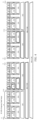
- FIG. 4 shows an 802.11be 80 MHz subcarrier design.
- a 240 MHz bandwidth and a 320 MHz bandwidth are added to the 802.11be, where the 240 MHz is obtained by directly concatenating three 802.11be 80 MHz subcarriers, and the 320 MHz is obtained by directly concatenating four 802.11be 80 MHz subcarriers.
- indexes of data subcarriers and pilot subcarriers in RU26 are listed in table 1.
- Table 1 RU1-RU18 RU19-RU36 Pilot location 26-tone RU -499 -474 13 38 ⁇ -494, -480 ⁇ , ⁇ -468, -454 ⁇ , ⁇ -440, - 426 ⁇ , ⁇ -414, -400 ⁇ , ⁇ -386, -372 ⁇ , ⁇ -360, -346 ⁇ , ⁇ -334, -320 ⁇ , ⁇ -306, -292 ⁇ , -473 -448 39 64 -445 -420 67 92 ⁇ -280, -266 ⁇ , ⁇ -246, -232 ⁇ , ⁇ -220, - 206 ⁇ , ⁇ -192, -178 ⁇ , ⁇ -166, -152 ⁇ , ⁇ -140, -126 ⁇ , ⁇ -112, -98 ⁇ , ⁇ -86, -72 ⁇ , ⁇ -58, -44 ⁇ ,
- each row in the 2 nd column and the 3 rd column indicates one RU.
- the last row in the 2 nd column indicates RU18 [-38: -13].
- Locations for RU18 are a subcarrier numbered - 38 to a subcarrier numbered -13.
- the 4 th column sequentially indicates pilot subcarrier indexes for a corresponding 26-tone RU.
- the 1 st 26-tone RU includes a subcarrier numbered -499 to a subcarrier numbered -474, where pilot subcarriers are a subcarrier numbered -494 and a subcarrier numbered -480.
- indexes of data subcarriers and pilot subcarriers in RU52 are listed table 2.
- Table 2 RU1-RU16 Pilot location 52-tone RU -499 -448 ⁇ -494, -480, -468, -454 ⁇ , ⁇ -440, -426, -414, -400 ⁇ , ⁇ -360, - 346, -334, -3201, ⁇ -306, -292, -280, -266 ⁇ , ⁇ -246, -232, -220, - 206 ⁇ , ⁇ -192,-178,-166,-152 ⁇ , ⁇ -112, -98, -86, -72 ⁇ , ⁇ -58,-44,-32,-18 ⁇ , ⁇ 18, 32, 44, 58 ⁇ , ⁇ 72, 86, 98, 112 ⁇ , ⁇ 152, 166, 178, 192 ⁇ , ⁇ 206, 220, 232, 246 ⁇ , ⁇ 266, 280,
- indexes of data subcarriers and pilot subcarriers in RU106 are listed in table 3.
- Table 3 RU1-RU8 Pilot location 106-tone RU -499 -394 ⁇ -494, -468, -426, -400 ⁇ , ⁇ -360, -334, -292, -266 ⁇ , ⁇ -246, -220, -178, -152 ⁇ , ⁇ -112, -86, -44, -18 ⁇ , ⁇ 18, 44, 86, 112 ⁇ , ⁇ 152, 178, 220, 246 ⁇ , ⁇ 266, 292, 334, 360 ⁇ , ⁇ 400, 426, 468, 494 ⁇ -365 -260 -252 -147 -118 -13 13 118 147 252 260 365 394 499
- indexes of data subcarriers and pilot subcarriers in RU242 are listed in table 4.
- Table 4 RU1-RU4 Pilot location 242-tone RU -500 -259 ⁇ -494, -468, -426, -400, -360, -334, -292, -266 ⁇ , ⁇ -246, - 220, -178, -152, -112, -86, -44, -18 ⁇ , ⁇ 18, 44, 86, 112, 152, 178, 220, 246 ⁇ , ⁇ 266, 292, 334, 360, 400, 426, 468, 494 ⁇ -253 -12 12 253 259 500
- indexes of data subcarriers and pilot subcarriers in RU484 are listed in table 5.
- An 80 MHz 484-tone RU in the 802.11ax is an RU composed of 484 consecutive subcarriers.
- An 80 MHz 484-tone RU in the 802.11be is composed of 468 data subcarriers and 16 pilot subcarriers, and there are 5 direct current subcarriers or null subcarriers in the middle.
- subcarriers are numbered from -500 to -12.
- the 5 direct current subcarriers are numbered -258, -257, -256, -255, and -254.
- the 16 pilot subcarriers are numbered -494, -468, -426, -400, -360, -334, -292, -266, -246, -220, -178, -152, -112, -86, -44, and -18.
- indexes of data subcarriers and pilot subcarriers in RU996 are listed in table 6.
- An 80 MHz 996-tone RU in the 802.11be is composed of 980 data subcarriers and 16 pilot subcarriers, and there are 5 direct current subcarriers in the middle.
- subcarriers are numbered -500 to 500, and the 5 direct current subcarriers are numbered -2, -1, 0, 1, and 2.
- the 16 pilot subcarriers are numbered -468, -400, -334, -266, -220, -152, -86, -18, +18, +86, +152, +220, +266, +334, +400, and +468.
- the LTF sequence provided in this embodiment of this application is used for the 240 MHz bandwidth and the 320 MHz bandwidth, and the 240 MHz bandwidth and the 320 MHz bandwidth are constructed by using the tone plan shown in FIG. 4 .
- a subcarrier design of a 160 MHz bandwidth is based on two 80 MHz, that is, [subcarriers indexes for RUs in 80 MHz, subcarrier indexes for pilot locations]-521,80 MHz [subcarrier indexes for RUs in 80 MHz, subcarrier indexes for pilot locations]+521.
- the 240 MHz bandwidth is based on three 80 MHz.
- a subcarrier design of the 320 MHz bandwidth is based on two 160 MHz, that is, [subcarrier indexes in 160 MHz]-1024, [subcarrier indexes in 160 MHz]+1024.
- a bitmap is used to indicate a puncturing pattern. Each bit indicates whether one 20 MHz subchannel is punctured. For example, “0" indicates that the 20 MHz subchannel corresponding to the bit is punctured, and "1" indicates that the 20 MHz subchannel corresponding to the bit is not punctured.
- bits from left to right sequentially correspond to 20 MHz subchannel with channel frequencies from low to high.
- Pattern 1 [1 1 1 1 1 1 1 1 1 1 1 1], corresponding to a channel bandwidth of 240 MHz and 3072 subcarriers.
- Pattern 2 [0 0 1 1 1 1 1 1 1 1], corresponding to an available channel bandwidth of 200 MHz.
- Pattern 3 [1 1 0 0 1 1 1 1 1 1 1], corresponding to an available channel bandwidth of 200 MHz.
- Pattern 4 [1 1 1 1 0 0 1 1 1 1 1], corresponding to an available channel bandwidth of 200 MHz.
- Pattern 5 [11 1 1 1 10 0 1 1 1 1], corresponding to an available channel bandwidth of 200 MHz.
- Pattern 6 [1 1 1 1 1 1 1 1 1 1 0 0 1 1], corresponding to an available channel bandwidth of 200 MHz.
- Pattern 7 [11 1 1 1 1 1 1 1 1 10 0], corresponding to an available channel bandwidth of 200 MHz.
- Pattern 8 [0 0 0 0 1 1 1 1 1 1 1], corresponding to an available channel bandwidth of 160 MHz.
- Pattern 9 [1 1 1 1 0 0 0 0 0 1 1 1 1], corresponding to an available channel bandwidth of 160 MHz.
- Pattern 10 [11 1 1 1 1 1 1 1 1 1 0 0 0 0], corresponding to an available channel bandwidth of 160 MHz.
- the channel puncturing patterns for the 320 MHz may be classified into two types: one type is compatible with 240 MHz puncturing, and the other type is not compatible with 240 MHz puncturing.
- “Compatible” means: After 240 MHz is formed by channel puncturing on 320 MHz, puncturing is further performed based on the 240 MHz formed by puncturing, that is, puncturing is continued on the 240 MHz formed by puncturing.
- Pattern 1 [11 1 1 1 1 1 1 1 1 1 1 1 1 1 1 1], corresponding to a channel bandwidth of 320 MHz and 4096 subcarriers.
- Pattern 2 [0 0 1 1 1 1 1 1 1 1 1 1 1 1], corresponding to an available channel bandwidth of 280 MHz.
- Pattern 3 [1 1 0 0 1 1 1 1 1 1 1 1 11 11], corresponding to an available channel bandwidth of 280 MHz.
- Pattern 4 [1 1 1 10 0 1 1 1 1 1 1 1 1 1 11], corresponding to an available channel bandwidth of 280 MHz.
- Pattern 5 [11 1 1 1 1 1 0 0 1 1 1 1 1 1 11], corresponding to an available channel bandwidth of 280 MHz.
- Pattern 6 [11 1 1 11 1 1 0 0 1 1 1 1 11], corresponding to an available channel bandwidth of 280 MHz.
- Pattern 7 [11 1 1 11 1 1 1 1 1 0 0 1 1 11], corresponding to an available channel bandwidth of 280 MHz.
- Pattern 8 [11 1 1 1 1 1 1 1 11 1 10 0 1 1], corresponding to an available channel bandwidth of 280 MHz.
- Pattern 9 [11 1 1 11 1 1 1 1 1 1 1 1 1 1 1 0 0], corresponding to an available channel bandwidth of 280 MHz.
- Pattern 10 [1 1 1 1 0 0 0 0 0 1 1 1 1 1 1 1], corresponding to an available channel bandwidth of 240 MHz.
- Pattern 11 [1 1 1 11 1 1 1 1 0 0 0 0 0 1 1 1 1], corresponding to an available channel bandwidth of 240 MHz.
- Pattern 12 [1 1 1 1 1 1 1 1 1 1 1 1 1 1 1 1 1 0 0 0 0], corresponding to an available channel bandwidth of 240 MHz.
- Pattern 13 [0 0 0 0 1 1 1 1 1 1 1 1 1 1], corresponding to an available channel bandwidth of 240 MHz.
- Puncturing is further performed based on the available channel bandwidth of 240 MHz formed in pattern 10 to obtain pattern 14 to pattern 22.
- Pattern 14 [0 0 1 1 0 0 0 0 0 1 1 1 1 1 1 1], corresponding to an available channel bandwidth of 200 MHz.
- Pattern 15 [1 1 0 0 0 0 0 0 0 0 1 1 1 1 1 1 1], corresponding to an available channel bandwidth of 200 MHz.
- Pattern 16 [1 1 1 1 1 0 0 0 0 0 0 0 0 1 1 1 1 1], corresponding to an available channel bandwidth of 200 MHz.
- Pattern 17 [1 1 1 1 0 0 0 0 0 1 1 1 0 0 1 1 1], corresponding to an available channel bandwidth of 200 MHz.
- Pattern 18 [1 1 1 1 1 0 0 0 0 0 1 1 1 1 1 0 0 1 1], corresponding to an available channel bandwidth of 200 MHz.
- Pattern 19 [1 1 1 1 0 0 0 0 0 1 1 1 1 1 1 1 0 0], corresponding to an available channel bandwidth of 200 MHz.
- Pattern 20 [0 0 0 0 0 0 0 0 0 0 0 0 1 1 1 1 1 1], corresponding to an available channel bandwidth of 160 MHz.
- Pattern 21 [1 1 1 1 1 0 0 0 0 0 0 0 0 0 0 1 1 1], corresponding to an available channel bandwidth of 160 MHz.
- Pattern 22 [1 1 1 1 1 0 0 0 0 0 1 1 1 1 1 0 0 0 0], corresponding to an available channel bandwidth of 160 MHz.
- Puncturing is further performed based on the available channel bandwidth of 240 MHz formed in pattern 11 to obtain pattern 23 to pattern 31.
- Pattern 23 [0 0 1 1 1 1 1 10 0 0 0 1 1 1 1], corresponding to an available channel bandwidth of 200 MHz.
- Pattern 24 [1 1 0 0 1 1 1 1 1 0 0 0 0 1 1 1], corresponding to an available channel bandwidth of 200 MHz.
- Pattern 25 [1 1 1 1 0 0 1 1 0 0 0 0 1 1 1 1], corresponding to an available channel bandwidth of 200 MHz.
- Pattern 26 [1 1 1 1 1 1 1 0 0 0 0 0 0 0 0 1 1 1], corresponding to an available channel bandwidth of 200 MHz.
- Pattern 27 [1 1 1 1 1 1 1 1 1 1 0 0 0 0 0 0 0 1 1], corresponding to an available channel bandwidth of 200 MHz.
- Pattern 28 [1 1 1 1 1 1 1 1 1 1 1 0 0 0 0 0 1 1 1 0 0], corresponding to an available channel bandwidth of 200 MHz.
- Pattern 29 [0 0 0 0 1 1 1 1 1 0 0 0 0 1 1 1], corresponding to an available channel bandwidth of 160 MHz.
- Pattern 30 [1 1 1 1 1 0 0 0 0 0 0 0 0 0 0 1 1 1], corresponding to an available channel bandwidth of 160 MHz.
- Pattern 31 [1 1 1 1 1 1 1 1 10 0 0 0 0 0 0 0 0 0], corresponding to an available channel bandwidth of 160 MHz.
- Puncturing is further performed based on the available channel bandwidth of 240 MHz formed in pattern 12 to obtain pattern 32 to pattern 40.
- Pattern 32 [0 0 1 1 1 1 1 1 1 1 1 1 1 0 0 0 0], corresponding to an available channel bandwidth of 200 MHz.
- Pattern 33 [1 1 0 0 1 1 1 1 1 1 1 10 0 0 0], corresponding to an available channel bandwidth of 200 MHz.
- Pattern 34 [1 1 1 1 0 0 1 1 1 1 1 1 1 0 0 0 0], corresponding to an available channel bandwidth of 200 MHz.
- Pattern 35 [1 1 1 1 1 1 1 0 0 1 1 1 1 1 0 0 0 0], corresponding to an available channel bandwidth of 200 MHz.
- Pattern 36 [1 1 1 1 1 1 1 1 1 1 1 0 0 1 1 0 0 0 0], corresponding to an available channel bandwidth of 200 MHz.
- Pattern 37 [1 1 1 1 1 1 1 1 1 1 1 1 1 1 1 0 0 0 0 0 0], corresponding to an available channel bandwidth of 200 MHz.
- Pattern 38 [0 0 0 0 1 1 1 1 1 1 1 1 1 1 0 0 0 0], corresponding to an available channel bandwidth of 160 MHz.
- Pattern 39 [1 1 1 1 1 0 0 0 0 0 1 1 1 1 1 0 0 0 0], corresponding to an available channel bandwidth of 160 MHz.
- Pattern 40 [1 1 1 1 1 1 1 1 1 1 1 1 0 0 0 0 0 0 0 0 0 0 0], corresponding to an available channel bandwidth of 160 MHz.
- Puncturing is further performed based on the available channel bandwidth of 240 MHz formed in pattern 13 to obtain pattern 41 to pattern 49.
- Pattern 41 [0 0 0 0 0 0 0 0 1 1 1 1 1 1 1 1], corresponding to an available channel bandwidth of 200 MHz.
- Pattern 42 [0 0 0 0 1 1 0 0 1 1 1 1 1 1 1], corresponding to an available channel bandwidth of 200 MHz.
- Pattern 43 [0 0 0 0 1 1 1 100 1 1 1 1 1], corresponding to an available channel bandwidth of 200 MHz.
- Pattern 44 [0 0 0 0 1 1 1 1 1 1 1 0 0 1 1 1], corresponding to an available channel bandwidth of 200 MHz.
- Pattern 45 [0 0 0 0 1 1 1 1 1 1 1 1 1 0 0 1 1], corresponding to an available channel bandwidth of 200 MHz.
- Pattern 46 [0 0 0 0 1 1 1 1 1 1 1 1 1 1 0 0], corresponding to an available channel bandwidth of 200 MHz.
- Pattern 47 [0 0 0 0 0 0 0 0 0 0 0 0 1 1 1 1 1 1], corresponding to an available channel bandwidth of 160 MHz.
- Pattern 48 [0 0 0 0 1 1 1 1 1 0 0 0 0 1 1 1], corresponding to an available channel bandwidth of 160 MHz.
- Pattern 49 [0 0 0 0 1 1 1 1 1 1 1 1 1 1 0 0 0 0], corresponding to an available channel bandwidth of 160 MHz.
- Pattern 1 320 MHz [1 1 1 1 1 1 1 1 1 1 1 1 1 1 1 1 1], corresponding to a channel bandwidth of 320 MHz and 4096 subcarriers.
- Pattern 2 280 MHz [0 0 1 1 1 11 1 1 1 11 1 1 1], corresponding to an available channel bandwidth of 280 MHz.
- Pattern 3 280 MHz [1 1 0 0 1 1 1 11 1 1 1 1 1 11], corresponding to an available channel bandwidth of 280 MHz.
- Pattern 4 280 MHz [11 1 10 0 1 1 1 1 1 1 1 1 1 1], corresponding to an available channel bandwidth of 280 MHz.
- Pattern 5 280 MHz [111 1 1 100 1 1 11 1 1 1], corresponding to an available channel bandwidth of 280 MHz.
- Pattern 6 280 MHz [111 1 1 11 100 11 1 1 1 1], corresponding to an available channel bandwidth of 280 MHz.
- Pattern 7 280 MHz [11 1 1 1 1 1 11 100 1 1 11], corresponding to an available channel bandwidth of 280 MHz.
- Pattern 8 280 MHz [11 1 11 1 1 1 11 1 10 0 1 1], corresponding to an available channel bandwidth of 280 MHz.
- Pattern 9 280 MHz [11 1 1 1 1 1 1 1 1 1 1 1 1 1 1 1 0 0], corresponding to an available channel bandwidth of 280 MHz.
- Pattern 10 240 MHz [1 1 1 10 0 0 0 1 1 1 1 1 1 1 1], corresponding to an available channel bandwidth of 240 MHz.
- Pattern 11 240 MHz [1 1 1 1 1 1 1 10 0 0 0 1 1 1 1], corresponding to an available channel bandwidth of 240 MHz.
- Pattern 12 240 MHz [1 1 1 1 1 1 1 1 1 1 1 1 1 10 0 0 0], corresponding to an available channel bandwidth of 240 MHz.
- Pattern 13 240 MHz [0 0 0 0 1 1 1 1 1 1 1 1 1 1], corresponding to an available channel bandwidth of 240 MHz.
- RU2*996 indicates two RU996, and may alternatively be represented as 2*RU996.
- RU3*996 may alternatively be represented as 3*RU996, and
- RU4*996 may alternatively be represented as 4*RU996.
- RUA+RUB is equivalent to RUB+RUA, and refers to a combination or concatenation of RUA and RUB.
- Modes considered for a 1x LTF sequence over the 240 MHz bandwidth include the descriptions in 2-1.
- Modes considered for a 1x LTF sequence over the 320 MHz bandwidth include the descriptions in 2-2.
- Modes considered for a 2x LTF sequence/4x LTF sequence over the 240 MHz bandwidth include content in table A below.
- Table A R U size RU 26 RU 52 RU 26 + RU 52 RU10 6 RU26 + RU 106 RU24 2 RU 484 RU24 2 + R U484 RU 996 RU484 + RU99 6 RU2* 996 RU48 4 + RU 2 *996 RU 3* 99 6 Modes 36* 3 16 * 3 4*3 8*3 4*3 4*3 2*3 4*3 1 * 3 8 3 6 1
- the 240 MHz is formed by concatenating three 80 MHz. Each 80 MHz has thirty-six 26-tone RUs with sequence numbers from small to large and corresponding frequencies from low to high. Implementation is similar for a 52-tone RU (RU52), a 106-tone RU (RU106), a 242-tone RU (RU242), a 484-tone RU (RU484), and a 996-tone RU (RU996).
- Multiple RU combination is to allocate a plurality of RUs to one STA.
- Each RU still uses data subcarrier locations and pilot subcarrier locations of the RU.
- RU26+RU52 uses its own data subcarrier locations and pilot locations, and RU52 uses its own data subcarrier locations and pilot subcarrier locations.
- RU26+RU52 has fixed combination or concatenation modes. There are 4 fixed combination modes in each 80 MHz, and therefore 12 combination or concatenation modes in the 240 MHz. Details are as follows:
- the 1 st 80 MHz in the 240 MHz bandwidth includes:
- the 2 nd 80 MHz in the 240 MHz bandwidth includes:
- the 5 th RU26+RU52 in the 240 MHz bandwidth is the 1 st RU26+RU52 in the 2 nd 80 MHz bandwidth. Implementation is the same for the following description.
- the 3 rd 80 MHz in the 240 MHz bandwidth includes:
- the 9 th RU26+RU52 in the 240 MHz bandwidth is the 1 st RU26+RU52 in the 3 rd 80 MHz bandwidth. Implementation is the same for the following description.
- each 80 MHz has 36 RU26, which are sequentially represented as the 1 st RU26, the 2 nd RU26, ..., and the 36 th RU26 from left to right (from a low frequency to a high frequency), as shown in FIG. 4 .
- the 240 MHz is composed of three 80 MHz, and RU26 included in the 240 MHz are sequentially represented as the 1 st RU26, the 2 nd RU26, ..., and the 108 th RU26 from left to right (from a low frequency to a high frequency).
- RU26 included in the 1 st 80 MHz of the 240 MHz are sequentially represented as the 1 st RU26, the 2 nd RU26, ..., the 36 th RU26; RU26 included in the 2 nd 80 MHz of the 240 MHz are sequentially represented as the 37 th RU26, the 38 th RU26, ..., and the 72 nd RU26; and RU26 included in the 3 rd 80 MHz of the 240 MHz are sequentially represented as the 73 rd RU26, the 74 th RU26, ..., and the 108 th RU26.
- RU26+RU106 has fixed combination or concatenation modes. There are 4 fixed combination modes in each 80 MHz, and therefore 12 combination or concatenation modes in the 240 MHz. Details are as follows:
- the 1 st 80 MHz in the 240 MHz bandwidth includes:
- the 2 nd 80 MHz in the 240 MHz bandwidth includes:
- the 5 th RU26+RU106 in the 240 MHz bandwidth is the 1 st RU26+RU106 in the 2 nd 80 MHz bandwidth. Implementation is the same for the following description.
- the 3 rd 80 MHz in the 240 MHz bandwidth includes:
- the 9 th RU26+RU106 in the 240 MHz bandwidth is the 1 st RU26+RU106 in the 3 rd 80 MHz bandwidth. Implementation is the same for the following description.
- both the X th RU26 and the Y th RU 106 are represented by being sequentially numbered from left to right (from a low frequency to a high frequency). This is similar to the foregoing description, and details are not described herein again.
- RU242+RU484 has fixed combination or concatenation modes. There are 4 fixed combination modes in each 80 MHz, and therefore 12 combination or concatenation modes in the 240 MHz. Details are as follows:
- the 1 st 80 MHz in the 240 MHz bandwidth includes:
- the 2 nd 80 MHz in the 240 MHz bandwidth includes:
- the 5 th RU242+RU484 in the 240 MHz bandwidth is the 1 st RU242+RU484 in the 2 nd 80 MHz bandwidth. Implementation is the same for the following description.
- the 3 rd 80 MHz in the 240 MHz bandwidth includes:
- the 9 th RU242+RU484 in the 240 MHz bandwidth is the 1 st RU242+RU484 in the 3 rd 80 MHz bandwidth. Implementation is the same for the following description.
- both the Z th RU242 and the X th RU484 are represented by being sequentially numbered from left to right (from a low frequency to a high frequency). This is similar to the foregoing description, and details are not described herein again.
- RU484+RU996 has fixed combination or concatenation modes. There are 8 fixed combination modes in the 240 MHz. Details are as follows:
- both the X th RU484 and the Y th RU996 are represented by being sequentially numbered from left to right (from a low frequency to a high frequency). This is similar to the foregoing description, and details are not described herein again.
- both the X th RU484 and the Y th RU996 are represented by being sequentially numbered from left to right (from a low frequency to a high frequency). This is similar to the foregoing description, and details are not described herein again.
- a mode of RU996+RU996+RU996 needs to be considered during design of a 240 MHz sequence, there is 1 mode in the 240 MHz, that is, a full-bandwidth mode, specifically, for example, a combination or concatenation of the 1 st RU996, the 2 nd RU996, and the 3 rd RU996.
- Modes considered for a 2x LTF sequence/4x LTF sequence over the 320 MHz bandwidth include content in table B below.
- Table B RU size RU 26 RU52 RU26 + RU52 RU10 6 RU26 +RU 106 RU24 2 RU48 4 RU24 2+R U484 RU 996 RU484 +RU99 6 RU 2*9 96 RU484 + RU 2*996 RU 3*9 96 RU3* 996+ RU48 4 RU 4* 99 6 Mode 1 36* 4 16*4 4*4 8*4 4*4 4*4 2*4 4*4 1*4 4*2 2 Not considered 4 8 1 Mode 2 36* 4 16*4 4*4 8*4 4*4 4*4 2*4 4*4 1*4 4*2 2 24 4 8 1 Mode 3 36* 4 16*4 4*4 8*4 4*4 4*4 4*4 2*4 4*4 1*4 4*2 3 *4 24 4 8 1 Mode 3 36* 4
- Mode 1 a mode with a full bandwidth, puncturing, and multiple RU combination in the 320 MHz. Mode 1 does not consider transmission in which 240 MHz is obtained by performing puncturing on the 320 MHz. In other words, sequence design mainly considers the full bandwidth, puncturing, and multiple RU modes in the 320 MHz/160+160 MHz.
- Each 80 MHz has thirty-six 26-tone RUs with sequence numbers from small to large and corresponding frequencies from low to high. Implementation is similar for a 52-tone RU (RU52), a 106-tone RU (RU106), a 242-tone RU (RU242), a 484-tone RU (RU484), and a 996-tone RU (RU996).
- RU52 52-tone RU
- RU106 106-tone RU
- RU242 242-tone RU
- RU484 484-tone RU
- RU996 996-tone RU
- Multiple RU combination is to allocate a plurality of RUs to one STA.
- Each RU still uses data subcarrier locations and pilot subcarrier locations of the RU.
- RU26+RU52 uses its own data subcarrier locations and pilot locations, and RU52 uses its own data subcarrier locations and pilot subcarrier locations.
- RU26+RU52 has fixed combination or concatenation modes. There are 4 fixed combination modes in each 80 MHz, and therefore 16 combination or concatenation modes in the 320 MHz. Details are as follows:
- both the X th RU26 and the Y th RU52 are represented by being sequentially numbered from left to right (from a low frequency to a high frequency). This is similar to the foregoing description, and details are not described herein again.
- RU26+RU106 has fixed combination or concatenation modes. There are 4 fixed combination modes in each 80 MHz, and therefore 16 combination or concatenation modes in the 320 MHz. Details are as follows:
- both the X th RU26 and the Y th RU106 are represented by being sequentially numbered from left to right (from a low frequency to a high frequency). This is similar to the foregoing description, and details are not described herein again.
- RU242+RU484 has fixed combination or concatenation modes. There are 4 fixed combination modes in each 80 MHz, and therefore 16 combination or concatenation modes in the 320 MHz. Details are as follows:
- both the X th RU242 and the Y th RU484 are represented by being sequentially numbered from left to right (from a low frequency to a high frequency). This is similar to the foregoing description, and details are not described herein again.
- RU484+RU996 has fixed combination or concatenation modes. There are 4 fixed combination modes in each of primary 160 MHz and secondary 160 MHz, and therefore 8 combination or concatenation modes in the 320 MHz. Details are as follows:
- both the X th RU484 and the Y th RU996 are represented by being sequentially numbered from left to right (from a low frequency to a high frequency). This is similar to the foregoing description, and details are not described herein again.
- RU2*996 covers two cases of primary 160 MHz and secondary 160 MHz. Details are as follows:
- the X th RU996 is represented by being sequentially numbered from left to right (from a low frequency to a high frequency). This is similar to the foregoing description, and details are not described herein again.
- RU3*996 refers to a combination of any three of four RU996. Details are as follows:
- the X th RU996 is represented by being sequentially numbered from left to right (from a low frequency to a high frequency). This is similar to the foregoing description, and details are not described herein again.
- the X th RU996 and the Y th RU484 are represented by being sequentially numbered from left to right (from a low frequency to a high frequency). This is similar to the foregoing description, and details are not described herein again.
- a combination mode of RU4*996+RU484 is a full-bandwidth mode of the 320 MHz. Details are as follows: the 1 st RU996, the 2 nd RU996, the 3 rd RU996, and the 4 th RU996.
- the X th RU996 is represented by being sequentially numbered from left to right (from a low frequency to a high frequency). This is similar to the foregoing description, and details are not described herein again.
- Mode 2 a mode with a full bandwidth, puncturing, and multiple RU combination modes in the 320 MHz, considering compatibility with RU2*996+ RU484 in the 240 MHz.
- Mode 2 considers compatibility with some circumstances in the 240 MHz. That is, when any 80 MHz is punctured from the 320 MHz or is not considered, a remaining RU2*996+RU484 formed by not considering one RU484 in RU3*996 is not considered.
- a puncturing scenario thereof is similar to patterns 14 to 49 (24 in total) in the puncturing scenario (A) of the 320 MHz.
- Mode 3 a mode with a full bandwidth, puncturing, and multiple RU combination modes in the 320 MHz, considering compatibility with a full bandwidth, puncturing, and multiple RU combination in the 240 MHz.
- Mode 3 considers compatibility with all circumstances with an MRU and puncturing in the 240 MHz. That is, when any 80 MHz is punctured from the 320 MHz or is not considered, a remaining RU2*996+RU484 formed by not considering one RU484 in RU3 *996 is not considered.
- a puncturing scenario thereof is similar to patterns 14 to 49 in the puncturing scenario (A) of the 320 MHz.
- the 240 MHz puncturing scenario is considered. Therefore, a quantity of cases of RU2*996 in mode 3 changes to 12 from 2 in mode 2.
- This embodiment of this application provides a plurality of possible LTF sequences.
- Some LTF sequences each have a smallest PAPR value in a full bandwidth.
- Some LTF sequences have a smallest maximum PAPR in comprehensive consideration of a full bandwidth and a plurality of puncturing patterns, and therefore they have optimal comprehensive performance in the full bandwidth and the plurality of puncturing patterns.
- Some LTF sequences comprehensively consider a PAPR in a full bandwidth, a plurality of puncturing patterns, and a plurality of multiple RUs, and therefore the LTF sequences have optimal comprehensive performance in the full bandwidth, the plurality of puncturing patterns, and the plurality of multiple RUs.
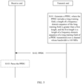
- an embodiment of this application provides a method for transmitting a physical layer protocol data unit.
- the method includes the following steps.
- S101 Generate a physical layer protocol data unit (physical protocol data unit, PPDU), where the PPDU includes a long training field (long training field, LTF), a length of a frequency-domain sequence of the LTF is greater than a first length, and the first length is a length of a frequency-domain sequence of an LTF of a PPDU transmitted over a channel whose bandwidth is 160 MHz.
- PPDU physical protocol data unit
- LTF long training field
- LTF long training field
- the first length is a length of a frequency-domain sequence of an LTF of a PPDU transmitted over a channel whose bandwidth is 160 MHz.
- S102 Send the PPDU over a target channel, where a bandwidth of the target channel is greater than 160 MHz.
- This embodiment of this application focuses on frequency-domain sequences of LTFs of PPDUs transmitted over 240 MHz and 320 MHz. Therefore, the foregoing steps may be simplified as follows:
- S201 Generate a PPDU, where the PPDU is transmitted over a channel whose bandwidth is 240 MHz/320 MHz, the PPDU includes an LTF, and a frequency-domain sequence of the LTF is any one of a plurality of possible LTF frequency-domain sequences provided below.
- S202 Send the PPDU over a channel whose bandwidth is 240 MHz/320 MHz.
- This embodiment of this application focuses on a plurality of possible frequency-domain sequences of LTFs (a frequency-domain sequence of an LTF is referred to as an LTF sequence for short below).
- a method for constructing an LTF sequence is first described .
- a specific method is as follows:
- the design criteria includes: consideration of a PAPR value in a case of a full bandwidth, a plurality of puncturing patterns, and a plurality of multiple RU combinations; and consideration of a phase rotation at a non-pilot location.
- the sequence design takes an optimal maximum PAPR in a plurality of cases (for example, a full bandwidth, puncturing, and a multiple RU) into consideration.
- Small RUs are concatenated into a large RU in a transmission bandwidth, and a sequence with an optimal PAPR on each type of RU (a multiple RU combination or a single RU) is selected.
- a maximum PAPR value of an obtained LTF is a result of considering a multi-stream scenario (for example, a size of a P matrix is 2x2, 4x4, 6x6, 8x8, 12x12, or 16x16) at a non-pilot location.
- LTF1x240M sequence [LTF1x80M 0 23 LTF1x80M 0 23 -LTF1x80M].
- LTF1x80M is an 80 MHz 1x LTF sequence in the 802.11ax standard. For a specific sequence, refer to the 802.11ax standard.
- the LTF1x240M sequence has relatively low PAPR values in various puncturing patterns for the 240 MHz.
- a method for obtaining the LTF1x240Msequence in 1-1 includes:
- the provided LTF 1x240M sequence has a minimum PAPR value when a full bandwidth, various puncturing patterns, and a plurality of streams are considered.
- an LTF1x240Msequence [LTF1x80M 0 23 LTF1x80M 0 23 LTF1x80M]
- an LTF1x240Msequence [LTF1x80M 0 23 -LTF1x80M 0 23 LTF1x80M”
- an LTF1X240M sequence [LTF1x80M 0 23 -LTF1x80M 0 23 -LTF1x80M] may alternatively be selected.
- LTF1x240Msequence [LTF1x160M 0 23 -LTF1x80M].
- LTF1x160M is a 160 MHz 1x LTF sequence in the 802.11ax standard.
- LTF1x80M is an 80 MHz 1x LTF sequence in the 802.11ax standard.
- 802.11ax standard refers to the 802.11ax standard.
- the LTF1x240M sequence has relatively low PAPR values in various puncturing patterns for the 240 MHz.
- a sequence structure of the LTF1x240M sequence that is determined in the method is [ ⁇ LTF1x160M 0 23 ⁇ LTF1x80M], Apart from this, other methods are the same as the foregoing sequence construction method.
- LTF1x240Msequence [LTF1x80MHz left 0 -LTF1x80MHz right 0 23 - LTF1x80MHz left 0 LTF1x80MHz right 0 23 LTF1x80MHz lefl 0 LTF1x80MHz right ].
- LTF1xSOMHz left is an 80Mhz left 1x LTF sequence in the 802.11ax standard.
- LTF1x80MHz right is an 80MHz right 1x LTF sequence in the 802.11ax standard.
- the LTF1x240Msequence has a relatively low PAPR value in puncturing pattern 1 for the 240 MHz.
- the PAPR value of the LTF1x240M sequence in puncturing pattern 1 for the 240 MHz is 7.3553 dB.
- a sequence structure of the LTF1x240M sequence that is determined in the method is [LTF1x80MHz left 0 ⁇ LTF1x80MHz right 0 23 ⁇ L TF1x80MHz left 0 ⁇ LTF1x80MHz right 0 23 ⁇ LTF1x80MHz left 0 ⁇ LTF1x80MHz right ].
- other methods are the same as the foregoing sequence construction method.
- LTF1x240M sequence [LTF1x80MHz left 0 LTF1x80MHz right 0 23 LTF1x80MHz left 0 LTF1x80MHz right 0 23 -LTF1x80MHz left 0 -LTF1x80MHz right ].
- LTF1x80MHz left is an 80MHz left 1x LTF sequence in the 802.11ax standard.
- LTF1x80MHz right is an 80MHz right 1x LTF sequence in the 802.11ax standard.
- the LTF1x240M sequence has relatively low PAPR values in various puncturing patterns for the 240 MHz.
- a sequence structure of the LTF1x240M sequence that is determined in the method is [LTF1x80MHz left 0 ⁇ LTF1x80MHz right 0 23 ⁇ LTF1x80MHz left 0 ⁇ LTF1x80MHz right 0 23 ⁇ LTF1x80MHz left 0 ⁇ LTF1x80MHz right ].
- other methods are the same as the foregoing sequence construction method.
- LTF1x320M sequence [LTF1x80M 0 23 LTF1x80M 0 23 -LTF1x80M 0 23 - LTF1x80M].
- LTF1x80M is an 80 MHz 1x LTF sequence in the 802.11ax standard. For a specific sequence, refer to the 802.11ax standard.
- anLTF1x320M sequence [LTF1x80M 0 23 LTF1x80M 0 23 LTF1x80M 0 23 -LTF1x80M]
- an LTF1x320M sequence [LTF1x80M 0 23 LTF1x80M 0 23 LTF1x80M 0 23 LTF1x80M]
- an LTF1x320M sequence [LTF1x80M 0 23 -LTF1x80M 0 23 LTF1x80M 0 23 LTF1x80M 0 23 LTF1x80M]
- an LTF1x320M sequence [LTF1x80M 0 23 -LTF1x80M 0 23 -LTF1x80M 0 23 LTF1x80M]
- an LTF1x320M sequence [LTF1x80M 0 23 -LTF1x80M 0 23 -LTF1x80M 0 23 -LTF1x80M]
- the LTF1x320M sequence has relatively low PAPR values in the puncturing patterns in (A) of the 320 MHz (that is, 240 MHz puncturing is compatible). For example, a PAPR value of the LTF1x320M sequence in a puncturing pattern in the puncturing patterns in (A) of the 320 MHz is 9.0837 dB. PAPR values in the other puncturing patterns each are less than 9.0837 dB. For example, a PAPR value is 8.9944 dB in puncturing pattern 1.
- PAPR values of the LTF1x320M sequence in the puncturing patterns in (B) of the 320 MHz are listed in table 14 below.
- Table 14 Sequence: PAPR [dB] LTF1x320M [LTF1x80M 0 23 LTF1x80M 0 23 -LTF1x80M 0 23 -LTF1x80M] Pattern 1: 320 MHz [1 1 1 1 1 1 1 1 1 1 1 1 1 1] 8.9944 Pattern 2: 280 MHz [x x 1 1 1 1 1 1 1 1 1 1 1 1] 8.0424 Pattern 3: 280 MHz [1 1 x x 1 1 1 1 1 1 1 1 1 1 1] 8.2230 Pattern 4: 280 MHz [1 1 1 1 x x 1 1 1 1 1 1 1 1 1 1] 8.8837 Pattern 5: 280 MHz [1 1 1 1 1 1 x x 1 1 1 1 1 1] 8.9778 Pattern 6:
- a method for obtaining the LTF1x320M sequence in 2-1 includes:
- LTF1x320M sequence [LTF1x80M 0 23 LTF1x80M 0 23 -LTF1x80M 0 23 LTF1x80M].
- LTF1x80M is an 80 MHz 1x LTF sequence in the 802.11ax standard. For a specific sequence, refer to the 802.11ax standard.
- the LTF1x320M sequence has relatively low PAPR values in the puncturing patterns in (B) of the 320 MHz (that is, 240 MHz puncturing is incompatible). Specifically, a PAPR value of the LTF1x320M sequence in puncturing pattern 1 for the 320 MHz is 7.5364 dB.
- LTF1x320M sequence [LTF1x160M 0 23 -LTF1x160M].
- LTF1x160M is a 160 MHz 1x LTF sequence in the 802.11ax standard. For a specific sequence, refer to the 802.11ax standard.
- the LTF1x320M sequence has relatively low PAPR values in various puncturing patterns for the 320 MHz.
- a PAPR value of the LTF1x320M sequence in a puncturing pattern in the puncturing patterns in (A) of the 320 MHz is 9.4002 dB.
- PAPR values in the other puncturing patterns each are less than 9.4002 dB.
- a PAPR value is 8.4364 dB in puncturing pattern 1.
- PAPR values of the LTF1x320M sequence in puncturing patterns 1 to 13 for the 320 MHz are listed in table 15 below.
- LTF1x320M sequence [LTF1x80MHz left 0 LTF1x80MHz right 0 23 - LTF1x80MHz left 0 -LTF1x80MHz right 0 23 -LTF1x80MHz left 0 -LTF1x80MHz right 0 23 -LTF1x80MHz left 0 LTF1x80MHz right ].
- LTF1x80MHz left is an 80MHz left 1x LTF sequence in the 802.11ax standard.
- LTF1x80MHz right is an 80MHz right 1x LTF sequence in the 802.11ax standard.
- a PAPR value of the LTF1x320M sequence in puncturing pattern 1 in the puncturing patterns in (A) of the 320 MHz is 8.1866 dB.
- LTF1x320M sequence [LTF1x80MHz left 0 LTF1x80MHz right 0 23 LTF1x80MHz left 0 LTF1x80MHz right 0 23 -LTF1x80MHz left 0 -LTF1x80MHz right 0 23 -LTF1x80MHz left 0 - LTF1x80MHz right ].
- LTF1x80MHz left is an 80MHz left 1x LTF sequence in the 802.11ax standard.
- LTF1x80MHz right is an 80MHz right 1x LTF sequence in the 802.11ax standard.
- a PAPR value of the LTF1x320M sequence in a puncturing pattern in the puncturing patterns in (A) of the 320 MHz is 9.0837 dB.
- PAPR values in the other puncturing patterns each are less than 9.0837 dB.
- LTF1x320M sequence [LTF1x80MHz left 0 -LTF1x80MHz right 0 23 - LTF1x80MHz left 0 LTF 1x80MHz right 0 23 LTF1x80MHz left 0 LTF1x80MHz right 0 23 LTF1x80MHz left 0 LTF1x80MHz right ].
- LTF1x80MHz left is an 80MHz left 1x LTF sequence in the 802.11ax standard.
- LTF1x80MHz right is an 80MHz right 1x LTF sequence in the 802.11 ax standard.
- 802.11ax standard refer to the 802.11ax standard.
- a PAPR value of the LTF1x320M sequence in puncturing pattern 1 for the 320 MHz is 6.2230 dB.
- LTF1x320M sequence [LTF1x80MHz left 0 -LTF1x80MHz right 0 23 LTF1x80MHz left 0 LTF1x80MHz right 0 23 LTF1x80MHz left 0 LTF1x80MHz right 0 23 -LTF1x80MHz left 0 - LTF1x80MHz right ].
- LTF1x80MHz left is an 80MHz left 1x LTF sequence in the 802.11ax standard.
- LTF1x80MHz right is an 80MHz right 1x LTF sequence in the 802.11ax standard.
- the 802.11ax standard refer to the 802.11ax standard.
- LTF2x240M sequence [LTF2x80M 0 23 LTF2x80M 0 23 LTF2x80M].
- LTF2x80M is an 80 MHz 2x LTF sequence in the 802.11ax standard. For a specific sequence, refer to the 802.11ax standard.
- the LTF2x240M sequence has relatively low PAPR values in various cases (including a full bandwidth of the 240 MHz, various puncturing patterns for the 240 MHz, and various multiple RU combinations for the 240 MHz) in table A of the 240 MHz.
- a PAPR value of the LTF2x240M sequence in the full bandwidth, a puncturing pattern, or an RU (or a multiple RU combination) is 10.9621 dB.
- PAPR values in the other puncturing patterns each are less than 10.9621 dB.
- a PAPR value is 10.9621 dB in the full bandwidth or puncturing pattern 1.
- the sequence has relatively low PAPR values in various cases (including a full bandwidth of the 240 MHz, various puncturing patterns for the 240 MHz, and various multiple RU combinations for the 240 MHz) in table A of the 240 MHz.
- the sequence has the following PAPR values on RUs (including a plurality of RU combinations or single RUs) in the 1 st 80 MHz, the 2 nd 80 MHz, and the 3 rd 80 MHz.
- a value at a corresponding location in the row for RU52 in the table represents a PAPR value on RU26 at the corresponding location.
- a value at a corresponding location in the row for RU106 in the table represents a PAPR value on RU26 at the corresponding location.
- values from left to right in the 1 st row of the foregoing table are sequentially PAPR values on the 1 st RU26 to the 36 th RU26 from left to right in 80 MHz for the sequence.
- Values from left to right in the 2 nd row of the foregoing table are sequentially PAPR values on the 1 st RU52 to the 16 th RU52 from left to right in 80 MHz for the sequence.
- Values from left to right in the 3 rd row of the foregoing table are sequentially PAPR values on the 1 st RU106 to the 8 th RU106 from left to right in 80 MHz for the sequence.
- Values from left to right in the 4 th row of the foregoing table are sequentially PAPR values on the 1 st RU242 to the 4 th RU242 from left to right in 80 MHz for the sequence.
- Values from left to right in the 5 th row of the foregoing table are sequentially PAPR values on the 1 st RU484 and the 2 nd RU484 from left to right in 80 MHz for the sequence.
- a value in the 6 th row of the foregoing table is a PAPR value on an RU996 in 80 MHz for the sequence.
- Values in the 7 th row of the foregoing table are PAPR values on the 1 st RU26+RU52 to the 4 th RU26+RU52 in each 80 MHz for the sequence.
- Values in the 8 th row of the foregoing table are PAPR values on the 1 st RU26+RU106 to the 4 th RU26+RU106 in each 80 MHz for the sequence.
- Values in the 9 th row of the foregoing table are PAPR values on the 1 st RU242+RU484 to the 4 th RU242+RU484 in each 80 MHz for the sequence.
- a value in the 10 th row of the foregoing table is a PAPR value on an RU combination (the combination is RU242+RU242, which is formed by the 1 st RU242 and the 4 th RU242 in each 80 MHz) in the 80 MHz for the sequence.
- PAPR values in a PAPR value table for other RUs of 80 MHz in this specification one to one correspond to the RUs described in the previous paragraph.
- the following description provides only PAPR values in a table. A correspondence between a PAPR value and an RU in the table is not described again.
- the sequence has the following PAPR values on other RUs in more than 80 MHz (namely, RU combinations) in table A. 7.77 23 9.18 04 7.77 23 9.05 11 7.77 23 9.18 04 7.77 23 9.05 11 RU484+RU996 9.89 21 8.73 3 8.92 56 10.4 67 9.86 54 8.57 81 9.32 01 10.3 64 9.892 1 8.73 3 8.925 6 10.46 7 9.865 4 8.578 1 9.320 1 10.364 RU242+R U484+RU 996 9.9264 10.716 9.9264 10.716 9.9264 10.71 6 RU484+RU2*996 9.2012 9.422 9.2012 RU2*996 10.9621 RU3*996
- values from left to right in the 1 st row of the foregoing table are sequentially PAPR values on the RU combination in the 1 st mode to the RU combination in the 8 th mode of RU484+RU996 in the 240 MHz described above.
- Values from left to right in the 2 nd row of the table are sequentially PAPR values on the RU combination in the 1 st mode to the RU combination in the 16 th mode of RU242+RU484+RU996 in the 240 MHz described above.
- Values from left to right in the 3 rd row of the table are sequentially PAPR values on the RU combination in the 1 st mode to the RU combination in the 6 th mode of RU484+2*RU996 in the 240 MHz described above.
- Values from left to right in the 4 th row of the table are sequentially PAPR values on the RU combination in the 1 st mode to the RU combination in the 3 rd mode of 2*RU996 in the 240 MHz described above.
- a value in the 5 th row of the table is a PAPR value on 3*RU996 in the 240 MHz described above.
- a correspondence between a PAPR value of an RU in more than 80 MHz (namely, an RU combination) in the foregoing table and the RU combination is applicable to a PAPR value table for other RUs in more than 80 MHz in this specification.
- PAPR values in a PAPR value table for other RUs in more than 80 MHz (namely, RU combinations) one to one correspond to the RU combinations described in the previous paragraph.
- the following description provides only PAPR values in a table. A correspondence between a PAPR value and an RU combination in the table is not described again.
- LTF2x240M sequence [LTF2x160M 0 23 LTF2x80M].
- LTF2x160M is a 160 MHz 2x LTF sequence in the 802. 11ax standard.
- LTF2x80M is an 80 MHz 2x LTF sequence in the 802.11ax standard. For specific sequences, refer to the 802.11ax standard.
- the LTF2x240M sequence has relatively low PAPR values in various cases (including a full bandwidth of the 240 MHz, various puncturing patterns for the 240 MHz, and various multiple RU combinations for the 240 MHz) in table A of the 240 MHz.
- a PAPR value of the LTF2x240M sequence in the full bandwidth or puncturing pattern 1 for the 240 MHz is 9.6089 dB.
- the sequence has relatively low PAPR values in various cases (including a full bandwidth of the 240 MHz, various puncturing patterns for the 240 MHz, and various multiple RU combinations for the 240 MHz) in table A of the 240 MHz.
- the sequence has the following PAPR values on RUs (including a plurality of RU combinations or single RUs) in the 1 st 80 MHz, the 2 nd 80 MHz, and the 3 rd 80 MHz.
- PAPR value table for the RUs in the 2 nd 80 MHz
- the sequence has the following PAPR values on other RUs in more than 80 MHz (namely, RU combinations) in table A: 8.57 79 9.724 2 8.857 7.506 7 8.541 8 8.112 2 8.206 5 9.455 4 RU484+RU996 8.42 93 8.737 6 9.454 3 8.527 5 9.242 9.015 2 7.450 5 8.499 6 9.350 7 8.994 7 7.844 6 8.475 5 8.795 8.737 6 8.947 9 8.698 4 RU24 2+R U484 +RU 996 9.6089 RU3*996
- LTF2x240M sequence [LTF2x160M 0 23 -LTF2x80M].
- LTF2x160M is a 160 MHz 2x LTF sequence in the 802. 11ax standard.
- LTF2x80M is an 80 MHz 2x LTF sequence in the 802.11ax standard. For specific sequences, refer to the 802.11ax standard.
- the LTF2x240M sequence has relatively low PAPR values in various cases (including a full bandwidth of the 240 MHz, various puncturing patterns for the 240 MHz, and various multiple RU combinations for the 240 MHz) in table A of the 240 MHz.
- a PAPR value of the LTF2x240M sequence in the full bandwidth, a puncturing pattern, or an RU (or a multiple RU combination) is 9.7242 dB.
- PAPR values in the other puncturing patterns each are less than 9.7242 dB.
- the sequence has relatively low PAPR values in various cases (including a full bandwidth of the 240 MHz, various puncturing patterns for the 240 MHz, and various multiple RU combinations for the 240 MHz) in table A of the 240 MHz.
- the sequence has the following PAPR values on RUs (including a plurality of RU combinations or single RUs) in the 1 st 80 MHz, the 2 nd 80 MHz, and the 3 rd 80 MHz.
- PAPR table for the RUs in the 1 st 80 MHz and the 3 rd 80 MHz PAPR table for the RUs in the 1 st 80 MHz and the 3 rd 80 MHz:
- the sequence has the following PAPR values on other RUs in more than 80 MHz (namely, RU combinations or single RUs) in table A: 8.57 79 9.724 2 8.857 7.506 7 9.106 4 7.911 8 8.577 9 9.471 3 RU484+RU996 8.42 8.737 9.454 8.527 9.242 9.015 7.450 8.499 9.05 9.237 8.812 8.684 8.632 8.325 9.4 8.1 RU242+ 93 6 3 5 2 5 6 68 4 4 3 5 2 718 413 RU484+ RU996 8.8238 9.049 9.7195 9.5351 8.7437 9.049 RU484+RU2*996 7.8267 9.4879 7.927 RU2*996 8.7432 RU3*996
- LTF2x240M sequence [LTF2x80M part1 LTF2x80M part2 -LTF2x80M part3 LTF2x80M part4 LTF2x80M part5 0 23 LTF2x80M part1 LTF2x80M part2 -LTF2x80M part3 -LTF2x80M part4 -LTF2x80M part5 0 23 LTF2x80M part1 LTF2x80M part2 -LTF2x80M part3 LTF2x80M part4 LTF2x80M part5 ].
- LTF2x80M part1 , LTF2x80M part2 , LTF2x80M part3 , LTF2x80M part4 , and LTF2x80M part5 are respectively an 80MHz part1 2x LTF sequence, an 80MHz part2 2x LTF sequence, an 80MHz part3 2x LTF sequence, an 80MHz part4 2x LTF sequence, and an 80MHz part5 2x LTF sequence in the 802.11ax standard. For specific sequences, refer to the 802.11ax standard.
- the LTF2x240M sequence has relatively low PAPR values in various cases (including a full bandwidth of the 240 MHz, various puncturing patterns for the 240 MHz, and various multiple RU combinations for the 240 MHz) in table A of the 240 MHz.
- a PAPR value of the LTF2x240M sequence in puncturing pattern 1 for the 240 MHz is 9.4304 dB.
- the sequence has the following PAPR values on RUs (including a plurality of RU combinations or single RUs) in the 1 st 80 MHz, the 2 nd 80 MHz, and the 3 rd 80 MHz.
- the sequence has the following PAPR values on other RUs in more than 80 MHz (namely, RU combinations or single RUs) in table A: 9.049 8 9.428 8 8.279 6 8.740 2 8.034 8 9.075 1 9.100 5 9.1825 RU484+RU99 6 8.731 7 8.403 9 9.323 1 9.041 9 8.676 2 7.766 1 8.834 7 8.668 3 8.313 5 7.875 8 8.597 4 8.771 2 8.254 8 8.505 3 9.089 7 8.845 9 RU242+RU48 4+RU996 9.3606 RU3*996
- LTF2x240M sequence [LTF2x80M part1 -LTF2x80M part2 -LTF2x80M part3 - LTF2x80M part4 LTF2x80M part5 0 23 -LTF2x80M part1 LTF2x80M part2 -LTF2x80M part3 -LTF2x80M part4 LTF2x80M part5 0 23 LTF2x80M part1 LTF2x80M part2 -LTF2x80M part3 LTF2x80M part4 LTF2x80M part5 ].
- LTF2x80M part1 , LTF2x80M part2 , LTF2x80M part3 , LTF2x80M part4 , and LTF2x80M part5 are respectively an 80MHz part1 2x LTF sequence, an 80MHz part2 2x LTF sequence, an 80MHz part3 2x LTF sequence, an 80MHz part4 2x LTF sequence, and an 80MHz part5 2x LTF sequence in the 802.11ax standard. For specific sequences, refer to the 802.11ax standard.
- the LTF2x240M sequence has relatively low PAPR values in various cases (including a full bandwidth of the 240 MHz, various puncturing patterns for the 240 MHz, and various multiple RU combinations for the 240 MHz) in table A of the 240 MHz.
- a PAPR value of the LTF2x240M sequence in a puncturing pattern is 9.6179 dB.
- PAPR values in the other puncturing patterns each are less than 9.6179 dB.
- the sequence has relatively low PAPR values in various cases (including a full bandwidth of the 240 MHz, various puncturing patterns for the 240 MHz, and various multiple RU combinations for the 240 MHz) in table A of the 240 MHz.
- the sequence has the following PAPR values on RUs (including a plurality of RU combinations or single RUs) in the 1 st 80 MHz, the 2 nd 80 MHz, and the 3 rd 80 MHz.
- the sequence has the following PAPR values on other RUs in more than 80 MHz (namely, RU combinations) in table A. 8.990 9 8.999 3 9.142 2 8.141 7 9.395 9 8.377 2 8.714 2 9.2975 RU484+RU99 6 8.502 4 8.963 9 8.366 2 8.610 9 8.668 2 8.911 9 7.861 9 8.670 1 8.755 6 9.517 5 8.791 4 8.345 6 8.433 6 8.292 3 9.292 7 8.552 RU242+RU48 4+RU996 9.2581 8.6046 9.5535 9.3087 8.3311 9.2032 RU484+RU2* 996 7.4638 9.5899 7.3504 RU2*996 8.7061 RU3*996
- LTF2x320M sequence [LTF2x80M 0 23 LTF2x80M 0 23 -LTF2x80M Ck -LTF2x80M].
- LTF2x80M is an 80 MHz 2x LTF sequence in the 802.11ax standard. For a specific sequence, refer to the 802.11ax standard.
- the sequence has relatively low PAPR values in various cases (including a full bandwidth of the 320 MHz, various puncturing patterns for the 320 MHz, and various multiple RU combinations for the 320 MHz) in table B of the 320 MHz.
- a PAPR value of the LTF2x320M sequence in the full bandwidth, a puncturing pattern, or an RU (or a multiple RU combination) is 10.9310 dB.
- PAPR values in the other puncturing patterns each are less than 10.9310 dB.
- a PAPR value is 10.4917 dB in the full bandwidth or puncturing pattern 1.
- the sequence has the following PAPR values on RUs (including a plurality of RU combinations or single RUs) in the 1 st 80 MHz, the 2 nd 80 MHz, the 3 rd 80 MHz, and the 4 th 80 MHz.
- the sequence has the following PAPR values on other RUs in more than 80 MHz (namely, RU combinations) in table B. 7.7723 9.1539 7.7919 9.0583 7.7723 9.1539 7.7919 9.0583 RU484+RU99 6 9.936 6 8.68 78 8.934 5 10.4 92 9.865 4 8.53 46 9.409 7 10.3 64 9.936 6 8.68 78 8.934 5 10.4 92 9.865 4 8.53 46 9.409 7 10.3 64 RU242+RU48 4+RU996 9.0793 9.991 10.152 10.714 10.02 10.931 9.0257 9.6559 RU484+RU3* 996 10.107 10.107 8.6961 8.6961 RU3*996 8.9611 9.9059 9.5392 10.689 9.3293 10.153 RU484+RU2* 996 9.3124 10.461 9.6129 10.431 8.9207 10.027 8.1092 9.0498 9.0633 9.8325 7.943 9.079 7.9181 8.9584
- values from left to right in the 1 st row of the foregoing table are sequentially PAPR values on the RU combination in the 1 st mode to the RU combination in the 8 th mode of RU484+RU996 in the 320 MHz described above.
- Values from left to right in the 2 nd row of the table are sequentially PAPR values on the RU combination in the 1 st mode to the RU combination in the 16 th mode of RU242+RU484+RU996 in the 320 MHz described above.
- Values from left to right in the 3 rd row of the table are sequentially PAPR values on the RU combination in the 1 st mode to the RU combination in the 8 th mode of RU484+3*RU996 in the 320 MHz described above.
- Values from left to right in the 4 th row of the table are sequentially PAPR values on the RU combination in the 1 st mode to the RU combination in the 4 th mode of 3*RU996 in the 320 MHz described above.
- Values from left to right in the 5 th row of the table are sequentially PAPR values on the RU combination in the 1 st mode to the RU combination in the 24 th mode of RU484+2*RU996 in the 320 MHz described above.
- Values from left to right in each sub-row of the 5 th row are sequentially PAPR values on the RU combination in the 1 st mode to the RU combination in the 6 th mode of RU484+2*RU996 in each 80 MHz of the 320 MHz.
- Values from left to right in the 6 th row of the table are sequentially PAPR values on the RU combination in the 1 st mode to the RU combination in the 12 th mode of 2*RU996 in the 320 MHz described above.
- Values from left to right in each sub-row of the 6 th row are sequentially PAPR values on the RU combination in the 1 st mode to the RU combination in the 3 rd mode of 2*RU996 in each 80 MHz of the 320 MHz.
- a value in the 7 th row of the table is a PAPR value on the 4*RU996 combination in the 320 MHz described above.
- a correspondence between a PAPR value of an RU in more than 80 MHz (namely, an RU combination) in the foregoing table and the RU combination is applicable to a PAPR value table for other RUs in more than 80 MHz in this specification.
- PAPR values in a PAPR value table for other RUs in more than 80 MHz (namely, RU combinations) one to one correspond to the RU combinations described in the previous paragraph.
- the following description provides only PAPR values in a table. A correspondence between a PAPR value and an RU combination in the table is not described again.
- LTF2x320M sequence [LTF2x160M 0 23 LTF2x160M].
- LTF2x160M is a 160 MHz 2x LTF sequence in the 802.11ax standard. For a specific sequence, refer to the 802.11ax standard.
- APAPR value of the LTF2x320M sequence in the full bandwidth or puncturing pattern 1 for the 320 MHz is 10.1655 dB.
- the sequence has relatively low PAPR values in various cases (including a full bandwidth of the 320 MHz, various puncturing patterns for the 320 MHz, and various multiple RU combinations for the 320 MHz) in table B of the 320 MHz.
- a PAPR value of the LTF2x320M sequence in the full bandwidth, a puncturing pattern, or an RU combination is 10.5867 dB.
- PAPR values in the other puncturing patterns each are less than 10.5867 dB.
- the sequence has the following PAPR values on RUs (including a plurality of RU combinations or single RUs) in the 1 st 80 MHz, the 2 nd 80 MHz, the 3 rd 80 MHz, and the 4 th 80 MHz.
- the sequence has the following PAPR values on other RUs in more than 80 MHz (namely, RU combinations) in table B. 8.5779 9.7901 8.8384 7.5067 8.5779 9.7901 8.8384 7.5067 RU484+RU99 6 9.8211 10.421 10.587 9.8727 9.8211 10.459 10.587 9.3701 RU484+RU3* 996 9.6089 9.3181 9.6089 9.2212 RU3*996 7.8599 7.8599 RU2*996 10.1655 RU4*996
- LTF2x320M sequence [LTF2x160M 0 23 -LTF2x160M].
- LTF2x160M is a 160 MHz 2x LTF sequence in the 802.11ax standard. For a specific sequence, refer to the 802.11ax standard.
- the LTF2x320M sequence has relatively low PAPR values in various cases (including a full bandwidth of the 320 MHz, various puncturing patterns for the 320 MHz, and various multiple RU combinations for 320 MHz) in table B of the 320 MHz.
- a PAPR value in the full bandwidth, a puncturing pattern, or an RU (or a multiple RU combination) is 11.2017 dB.
- the sequence has the following PAPR values on RUs (including a plurality of RU combinations or single RUs) in the 1 st 80 MHz, the 2 nd 80 MHz, the 3 rd 80 MHz, and the 4 th 80 MHz.
- the sequence has the following PAPR values on other RUs in more than 80 MHz (namely, RU combinations) in table B. 8.5779 9.7901 8.8384 7.5067 8.5779 9.7901 8.8384 7.5067 RU484+RU99 6 8.429 3 8.73 76 9.511 8 8.52 75 9.294 6 9.08 86 7.490 2 8.51 44 8.429 3 8.73 76 9.511 8 8.52 75 9.294 6 9.08 86 7.490 2 8.51 44 RU242+RU48 4+RU996 9.6939 10.684 10.19 9.1133 9.6939 10.34 10.034 9.4725 RU484+RU3* 996 8.968 9.5228 8.7432 9.5228 RU3*996 8.1123 9.8583 8.441 9.1406 10.129 9.5351 RU484+RU2* 996 10.555 11.202 9.392 8.1659 9.1577 9.0528 8.8054 9.1334 9.7195 9.5351 8.9477 9.049 9.2871 8.1322
- LTF2x320M sequence [LTF2x80M part1 LTF2x80M part2 -LTF2x80M part3 LTF2x80M part4 LTF2x80M part5 Ck LTF2x80M part1 LTF2x80M part2 -LTF2x80M part3 -LTF2x80M part4 -LTF2x80M part5 0 23 LTF2x80M part1 -LTF2x80M part2 LTF2x80M part3 LTF2x80M part4 -LTF2x80M part5 Ck LTF2x80M part1 LTF2x80M part2 -LTF2x80M part3 LTF2x80M part4 LTF2x80M part5 ].
- LTF2x80M part1 , LTF2x80M part2 , LTF2x80M part3 , LTF2x80M part4 , and LTF2x80M part5 are respectively an 80MHz part1 2x LTF sequence, an 80MHz part2 2x LTF sequence, an 80MHz part3 2x LTF sequence, an 80MHz part4 2x LTF sequence, and an 80MHz part5 2x LTF sequence in the 802. 11ax standard. For specific sequences, refer to the 802.11ax standard.
- the LTF2x320M sequence has relatively low PAPR values in various cases (including a full bandwidth of the 320 MHz, various puncturing patterns for the 320 MHz, and various multiple RU combinations for 320 MHz) in table B of the 320 MHz.
- the sequence has the following PAPR values on RUs (a plurality of RU combinations or single RUs) in the 1 st 80 MHz to the 4 th 80 MHz.
- the sequence has the following PAPR values on other RUs in more than 80 MHz (namely, RU combinations) in table B. 9.057 4 9.430 1 8.310 8 8.753 1 8.716 4 8.23 8.655 6 9.3442 RU484+RU99 6 8.751 8 8.369 2 9.309 1 9.023 3 8.632 7 7.790 6 8.793 4 8.713 9 9.054 4 8.255 5 8.052 2 8.396 7 8.959 2 8.412 6 8.743 2 8.905 4 RU242+RU48 4+RU996 9.3128 9.3606 8.7851 8.802 RU3*996 9.3274 RU4*996 9.3274 RU4*996 9.3274 RU4*996 9.3274 RU4*996 9.3274 RU4*996 9.3274 RU4*996 9.3274 RU4*996 9.3274 RU4*996 9.3274 RU4*996 9.3274 RU4*996 9.3274 RU4
- LTF2x320M sequence [LTF2x80M part1 -LTF2x80M part2 -LTF2x80M part3 - LTF2x80M part4 LTF2x80M part5 Ck -LTF2x80M part1 LTF2x80M part2 -LTF2x80M part3 -LTF2x80M part4 LTF2x80M part5 0 23 LTF2x80M part1 LTF2x80M part2 -LTF2x80M part3 LTF2x80M part4 LTF2x80M part5 Ck LTF2x80M part1 - LTF2x80M part2 -LTF2x80M part3 -LTF2x80M part4 -LTF2x80M part5 ].
- LTF2x80M part1 , LTF2x80M part2 , LTF2x80M part3 , LTF2x80M part4 , and LTF2x80M part5 are respectively an 80MHz part1 2x LTF sequence, an 80MHz part2 2x LTF sequence, an 80MHz part3 2x LTF sequence, an 80MHz part4 2x LTF sequence, and an 80MHz part5 2x LTF sequence in the 802. 11ax standard. For specific sequences, refer to the 802.11ax standard.
- the LTF2x320M sequence has relatively low PAPR values in various cases (including a full bandwidth of the 320 MHz, various puncturing patterns for the 320 MHz, and various multiple RU combinations for 320 MHz) in table B of the 320 MHz.
- the sequence has the following PAPR values on RUs (a plurality of RU combinations or single RUs) in the 1 st 80 MHz to the 4 th 80 MHz.
- the sequence has the following PAPR values on other RUs in more than 80 MHz (namely, RU combinations) in table B. 8.9909 9.0351 9.1822 8.1417 9.8931 7.8954 8.3108 8.1246 RU484+RU99 6 8.468 4 8.99 51 8.343 4 8.61 09 8.695 3 8.94 52 7.881 8.67 12 10.22 2 8.86 05 8.269 2 9.85 72 10.20 8 7.79 06 7.928 10.1 5 RU242+RU48 4+RU996 8.7956 9.8176 9.53 10.099 9.8289 8.4202 9.5776 9.4929 RU484+RU3* 996 9.9757 8.6326 8.9312 8.9612 RU3*996 9.3369 9.5801 9.5133 9.0196 10.118 10.075 RU484+RU2* 996 8.9206 9.594 9.3901 9.6588 8.3 8.6299 9.265 8.6646 9.5535 9.4094 8.4876 9.2206 10.213 9.2738 9.9448 9.3384 8.49
- LTF2x320M sequence [LTF2x80M _part1 , LTF2x80M _part2 , (-1)*LTF2x80M _part3 , LTF2x80M _part4 , LTF2x80M _part5 , 0 23 , (-1)*LTF2x80M _part1 , LTF2x80M _part2 , (-1)*LTF2x80M _part3 , (-1)*LTF2x80M _part4 , LTF2x80M _part5 , 0 23 , (-1)*LTF2x80M _part1 , (-1)*LTF2x80M _part2 , LTF2x80M _part3 , LTF2x80M _part4 , LTF2x80M _part5 , 0 23 , LTF2x80M _part1 , (-1)*LTF2x80M _part2
- the sequence has relatively low PAPR values in various cases (including a full bandwidth of the 320 MHz, various puncturing patterns for the 320 MHz, and various multiple RU combinations for the 320 MHz) in table B of the 320 MHz.
- PAPR values on RUs in the 1 st 80 MHz to the 4 th 80 MHz are provided below.
- the RUs are sorted in sequence. For example, RU26 in the 1 st 80 MHz are sequentially the 1 st to the 36 th RU26 in the 320 MHz bandwidth based on an order in the table; and RU26 in the 2 nd 80 MHz are sequentially the 37 th to the 72 nd RU26 in the 320 MHz bandwidth based on the order in the table.
- the sequence has the following PAPR values on other RUs in more than 80 MHz (namely, RU combinations or single RUs) in table B: 8.226 9.2131 9.4269 8.0198 7.8088 8.8753 9.3779 8.3036 RU484+RU996 7.6781 7.5651 RU2*996 9.319 9.2606 8.6742 9.1361 9.4099 8.8471 9.0799 9.2767 RU484+RU3*99 6 9.1911 8.8715 9.4079 8.7804 RU3*996 7.7631 RU4*996
- LTF2x320M sequence [LTF2x80M _part1 , LTF2x80M _part2 , (-1)*LTF2x80M _part3 , (-1)*LTF2x80M _part4 , (-1)*LTF2x80M _part5 , 0 23 , (-1)*LTF2x80M _part1 , (-1)*LTF2x80M _part2 , (-1)*LTF2x80M _part3 , (-1)*LTF2x80M _part4 , (-1)*LTF2x80M _part5 , 0 23 , (-1)*LTF2x80M _part1 , LTF2x80M _part2 , LTF2x80M _part3 , LTF2x80M _part4 , LTF2x80M _part5 , 0 23 , LTF2x80M _part5 , 0 23
- the sequence has relatively low PAPR values in various cases (including a full bandwidth of the 320 MHz, various puncturing patterns for the 320 MHz, and various multiple RU combinations for the 320 MHz) in table B of the 320 MHz.
- the sequence has the following PAPR values on RUs (a plurality of RU combinations or single RUs) in the 1 st 80 MHz to the 4 th 80 MHz.
- the sequence has the following PAPR values on other RUs in more than 80 MHz (namely, RU combinations or single RUs): 7.8418 10.047 RU2*996 9.9503 9.4954 9.3479 9.0787 9.834 8.7716 9.4144 9.5244 RU484+RU3*99 6 8.7827 9.2171 8.7827 8.8965 RU3*996 9.5890 RU4*996 9.7038 9.3527 8.3182 8.8433 9.4922 9.3837 9.3124 9.8853 8.8523 8.8747 8.2622 9.6814 RU2*996+ RU484 9.0595 10.043 8.7657 9.0575 8.9771 9.0549 8.5889 9.4114 9.0418 9.8471 8.6334 8.8241
- LTF2x320M sequence [LTF2x80M _part1 , LTF2x80M _part2 , (-1)*LTF2x80M _part3 , (-1)*LTF2x80M _part4 , (-1)*LTF2x80M _part5 , 0 23 , (-1)*LTF2x80M _part1 , (-1)*LTF2x80M _part2 , (-1)*LTF2x80M _part3 , (-1)*LTF2x80M _part4 , (-1)*LTF2x80M _part5 , 0 23 , (-1)*LTF2x80M _part1 , LTF2x80M _part2 , LTF2x80M _part3 , LTF2x80M _part4 , LTF2x80M _part5 , 0 23 , LTF2x80M _part5 , 0 23
- the sequence has relatively low PAPR values in various cases (including a full bandwidth of the 320 MHz, various puncturing patterns for the 320 MHz, and various multiple RU combinations for the 320 MHz) in table B of the 320 MHz.
- the sequence has the following PAPR values on RUs (a plurality of RU combinations or single RUs) in the 1 st 80 MHz to the 4 th 80 MHz.
- Table for the RUs in the 2 nd 80 MHz Table for the RUs in the 3 rd 80 MHz
- the sequence has the following PAPR values on other RUs in more than 80 MHz (namely, RU combinations or single RUs): 9.9503 9.4954 9.3479 9.0787 9.834 8.7716 9.4144 9.5244 8.7827 9.2171 8.7827 8.8965 9.7038 9.3527 8.3182 8.8433 9.4922 9.3837 9.3124 9.8853 8.8523 8.8747 8.2622 9.3814 9.0595 10.043 8.7657 9.0575 8.9771 9.0549 8.5889 9.4114 9.0418 9.8471 8.6334 8.8241 10.047 7.9376 8.9745 9.4879 7.9376 7.8418 8.6498 8.9745 7.8418 10.047 9.4879 8.6498 7.7723 9.0647 8.4855 9.9838 7.7723 8.0424 9.9091 7.9129 9.589
- LTF4x240M sequence [LTF4x80M 0 23 LTF4x80M 0 23 -LTF4x80M].
- LTF4x80M is an 80 MHz 4x LTF sequence in the 802.11ax standard. For a specific sequence, refer to the 802.11ax standard.
- the LTF4x240M sequence has a relatively low PAPR value in a full bandwidth, a puncturing pattern, or an RU (or a multiple RU combination) in the 240 MHz.
- a PAPR value of the sequence in the full bandwidth of 240 MHz is 9.8723 dB.
- PAPR values in the other puncturing patterns each are less than 9.8723 dB.
- the LTF4x240M sequence has relatively low PAPR values in table A of the 240 MHz.
- a PAPR value of the sequence in a puncturing pattern or a multiple RU is 9.7535 dB. PAPR values in the other puncturing patterns each are less than 9.7535 dB.
- the sequence has the following PAPR values on RUs (a plurality of RU combinations or single RUs) in the 1 st 80 MHz to the 3 rd 80 MHz.
- the sequence has the following PAPR values on other RUs in more than 80 MHz (namely, RU combinations) in table A: 8.745 9 8.582 2 8.745 9 8.582 2 8.929 8.875 9 8.959 3 8.8759 RU484+RU 996 9.647 7 9.721 5 9.346 3 9.872 3 9.647 7 9.721 5 9.433 3 9.872 3 9.537 5 9.360 8 9.579 5 9.774 8 9.486 9 9.167 3 9.579 5 9.780 6 RU242+RU 484+RU996 8.158 8.7457 9.5808 8.9032 8.158 8.698 RU484+RU 2*996 9.7535 9.7047 9.5495 RU2*996 8.9129 RU3*996
- LTF4x240M sequence [LTF4x160M 0 23 LTF4x80M].
- LTF4x160M is a 160 MHz 4x LTF sequence in the 802.11ax standard.
- LTF4x80M is an 80 MHz 4x LTF sequence in the 802.11ax standard. For specific sequences, refer to the 802.11ax standard.
- the LTF4x240M sequence has relatively low PAPR values in table A of the 240 MHz. For example, a PAPR value of the LTF4x240M sequence in the full bandwidth of the 240 MHz is 9.2127 dB.
- the sequence has the following PAPR values on RUs (a plurality of RU combinations or single RUs) in the 1 st 80 MHz to the 3 rd 80 MHz.
- the sequence has the following PAPR values on other RUs in more than 80 MHz (namely, RU combinations) in table A: 9.046 9 9.212 7 8.959 3 8.582 2 8.929 8.582 2 9.148 9.2127 RU4 84+R U996 7.834 9 8.047 7.598 9 8.078 5 8.346 5 7.972 4 8.193 4 7.839 3 8.346 5 9.070 6 8.395 8 8.03 7.735 8.318 9 8.383 2 8.341 RU2 42+R U484 +RU 996 8.9967 RU3 *996
- LTF4x240M sequence [LTF4x160M 0 23 -LTF4x80M].
- LTF4x160M is a 160 MHz 4x LTF sequence in the 802.11ax standard.
- LTF4x80M is an 80 MHz 4x LTF sequence in the 802.11ax standard. For specific sequences, refer to the 802.11ax standard.
- the LTF4x240M sequence has relatively low PAPR values in table A of the 240 MHz.
- a PAPR value of the sequence in the full bandwidth or a puncturing pattern for the 240 MHz is 9.7047 dB.
- PAPR values in the other puncturing patterns each are less than 9.7047 dB.
- the sequence has relatively low PAPR values in various cases (including a full bandwidth of the 240 MHz, various puncturing patterns for the 240 MHz, and various multiple RU combinations for the 240 MHz) in table A of the 240 MHz.
- the sequence has the following PAPR values on RUs (a plurality of RU combinations or single RUs) in the 1 st 80 MHz to the 3 rd 80 MHz.
- the sequence has the following PAPR values on other RUs in more than 80 MHz (namely, RU combinations) in table A: 9.046 9 9.212 7 8.959 3 8.582 2 8.745 9 8.875 9 9.313 2 8.7075 RU4 84+R U996 7.834 9 8.047 7.598 9 8.078 5 8.346 5 7.972 4 8.193 4 7.839 3 8.284 5 9.163 3 8.087 7 8.505 8 8.700 4 7.748 7 8.717 6 8.544 3 RU2 42+R U484 +RU 996 8.5636 8.5102 9.0885 8.9032 8.4782 8.6426 RU4 84+R U2*9 96 7.263 9.7047 7.8024 RU2 *996 9.219 RU3 *996
- LTF4x240M sequence [LTF4x80MHz left 0 LTF4x80MHz right 0 23 LTF4x80MHz left 0 -LTF4x80MHz right 0 23 LTF4x80MHz left 0 LTF4x80MHz right ].
- LTF4x80MHz left is an 80MHz left 4x LTF sequence in the 802.11ax standard.
- LTF4x80MHz right is an 80MHz right 4x LTF sequence in the 802.11ax standard. For specific sequences, refer to the 802.11ax standard.
- the LTF4x240M sequence has relatively low PAPR values in table A of the 240 MHz.
- a PAPR value of the LTF4x240M sequence in the full bandwidth of the 240 MHz is 9.2127 dB.
- the sequence has relatively low PAPR values in various cases (including a full bandwidth of the 240 MHz, various puncturing patterns for the 240 MHz, and various multiple RU combinations for the 240 MHz) in table A of the 240 MHz.
- the sequence has the following PAPR values on RUs (a plurality of RU combinations or single RUs) in the 1 st 80 MHz to the 3 rd 80 MHz.
- the sequence has the following PAPR values on other RUs in more than 80 MHz (namely, RU combinations) in table A: 9.046 9 9.212 7 8.959 3 8.582 2 8.929 8.582 2 9.148 9.2127 RU4 84+R U996 7.834 9 8.047 7.598 9 8.078 5 8.346 5 7.972 4 8.193 4 7.839 3 8.346 5 9.070 6 8.395 8 8.03 7.735 8.318 9 8.383 2 8.341 RU2 42+R U484 +RU 996 8.9967 RU3 *996
- LTF4x240M sequence [LTF4x80MHz left 0 LTF4x80MHz right 0 23 LTF4x80MHz left 0 -LTF4x80MHz right 0 23 -LTF4x80MHz left 0 -LTF4x80MHz right ].
- LTF4x80MHz left is an 80MHz left 4x LTF sequence in the 802.11ax standard.
- LTF4x80MHz right is an 80MHz right 4x LTF sequence in the 802.11ax standard. For specific sequences, refer to the 802.11ax standard.
- the LTF4x240M sequence has relatively low PAPR values in table A of the 240 MHz.
- a PAPR value of the sequence in the full bandwidth or a puncturing pattern for the 240 MHz is 9.7047 dB.
- PAPR values in the other puncturing patterns each are less than 9.7047 dB.
- the sequence has relatively low PAPR values in various cases (including a full bandwidth of the 240 MHz, various puncturing patterns for the 240 MHz, and various multiple RU combinations for the 240 MHz) in table A of the 240 MHz.
- the sequence has the following PAPR values on RUs (a plurality of RU combinations or single RUs) in the 1 st 80 MHz to the 3 rd 80 MHz.
- the sequence has the following PAPR values on other RUs in more than 80 MHz (namely, RU combinations) in table A: 9.046 9 9.212 7 8.959 3 8.582 2 8.745 9 8.875 9 9.313 2 8.7075 RU4 84+R U996 7.834 9 8.047 7.598 9 8.078 5 8.346 5 7.972 4 8.193 4 7.839 3 8.284 5 9.163 3 8.087 7 8.505 8 8.700 4 7.748 7 8.717 6 8.544 3 RU2 42+R U484 +RU 996 8.5636 8.5102 9.0885 8.9032 8.4782 8.6426 RU4 84+R U2*9 96 7.263 9.7047 7.8024 RU2 *996 9.219 RU3 *996
- LTF4x320M sequence [LTF4x80M 0 23 LTF4x80M 0 23 -LTF4x80M 0 23 -LTF4x80M].
- LTF4x80M is an 80 MHz 4x LTF sequence in the 802.11ax standard. For a specific sequence, refer to the 802.11ax standard.
- the LTF4x320M sequence has relatively low PAPR values in various cases (including a full bandwidth of the 320 MHz, various puncturing patterns for the 320 MHz, and various multiple RU combinations for the 320 MHz) in table B of the 320 MHz.
- a PAPR value of the sequence in a puncturing pattern for the 320 MHz is 10.7708 dB.
- PAPR values in the other puncturing patterns each are less than 10.7708 dB.
- a PAPR value is 10.3033 dB in puncturing pattern 1.
- the sequence has the following PAPR values on RUs (a plurality of RU combinations or single RUs) in the 1 st 80 MHz to the 4 th 80 MHz.
- the sequence has the following PAPR values on other RUs in more than 80 MHz (namely, RU combinations) in table B. 8.745 9 8.582 2 8.745 9 8.582 2 8.745 9 8.582 2 8.745 9 8.582 2 8.745 9 8.5822 RU484+R U996 9.647 7 9.792 9 9.346 3 9.872 3 9.647 7 9.721 5 9.494 7 9.872 3 9.647 7 9.792 9 9.346 3 9.872 3 9.647 7 9.721 5 9.494 7 9.872 3 RU242+R U484+RU 996 9.6212 9.8446 10.436 10.172 10.227 10.771 9.5687 9.3672 RU484+R U3*996 10.27 10.27 8.9129 8.9129 RU3*996 9.5702 9.3248 9.9801 10.419 9.7444 9.7008 RU484+R U2*996 9.8472 10.163 9.911 9.8872 9.6101 9.6519 8.158
- LTF4x320M sequence [LTF4x160M 0 23 LTF4x160M].
- LTF4x160M is a 160 MHz 4x LTF sequence in the 802.11ax standard. For a specific sequence, refer to the 802.11ax standard.
- the LTF2x320M sequence has relatively low PAPR values in various cases (including a full bandwidth of the 320 MHz, various puncturing patterns for the 320 MHz, and various multiple RU combinations for the 320 MHz) in table B of the 320 MHz.
- a PAPR value of the LTF4x320M sequence in the full bandwidth or puncturing pattern 1 for the 240 MHz is 9.9610 dB.
- the sequence has the following PAPR values on RUs (a plurality of RU combinations or single RUs) in the 1 st 80 MHz to the 4 th 80 MHz.
- the sequence has the following PAPR values on other RUs in more than 80 MHz (namely, RU combinations) in table B. 9.046 9 9.300 5 9.029 3 8.582 2 9.046 9 9.300 5 9.029 3 8.5822 RU484+R U996 7.807 8 8.032 3 7.540 7 8.152 2 8.346 5 8.034 8 8.193 4 7.829 5 7.807 8 8.032 3 7.540 7 8.152 2 8.346 5 8.034 8 8.193 4 7.829 5 RU242+R U484+RU 996 9.211 9.2872 8.9967 8.7201 RU3*996 9.961 RU4*996 9.961 RU4*996
- LTF4x320M sequence [LTF4x160M 0 23 -LTF4x160M].
- LTF4x160M is a 160 MHz 4x LTF sequence in the 802.11ax standard. For a specific sequence, refer to the 802.11ax standard.
- the LTF4x320M sequence has relatively low PAPR values in various cases (including a full bandwidth of the 320 MHz, various puncturing patterns for the 320 MHz, and various multiple RU combinations for the 320 MHz) in table B of the 320 MHz.
- a PAPR value of the sequence in a pattern for the 320 MHz is 10.2842 dB (if RU484+RU2*996 is considered) or 10.2793 dB (if RU484+RU2*996 is not considered).
- PAPR values in the other puncturing patterns each are less than 10.2793 dB.
- the sequence has the following PAPR values on RUs (a plurality of RU combinations or single RUs) in the 1 st 80 MHz to the 4 th 80 MHz.
- the sequence has the following PAPR values on other RUs in more than 80 MHz (namely, RU combinations) in table B.
- 9.046 9 9.300 5 9.029 3 8.582 2 9.046 9 9.300 5 9.029 3 8.5822 RU484+R U996 7.807 8 8.032 3 7.540 7 8.152 2 8.346 5 8.034 8 8.193 4 7.829 5 7.807 8 8.032 3 7.540 7 8.152 2 8.346 5 8.034 8 8.193 4 7.829 5 RU242+R U484+RU 996 9.6603 10.279 9.6764 9.6836 9.5247 9.7706 9.7151 9.8314 RU484+R U3*996 9.219 9.4159 9.219 9.4138 RU3*996 8.68 9.4991 8.4782 8.481 9.8112 9.7008 RU484+R U2*996 10.105 10.284 8.0493 8.812 8.8152 9.3773 8.6518 8.5538 9.0885 8.9032 8.
- LTF4x320M sequence [LTF4x80MHz left 0 LTF4x80MHz right 0 23 LTF4x80MHz left 0 -LTF4x80MHz right 0 23 -LTF4x80MHz left 0 LTF4x80MHz right 0 23 LTF4x80MHz left 0 LTF4x80MHz right ].
- LTF4x80MHz left is an 80MHz left 4x LTF sequence in the 802.11ax standard.
- LTF4x80MHz right is an 80MHz right 4x LTF sequence in the 802.11ax standard. For specific sequences, refer to the 802.11ax standard.
- the LTF4x320M sequence has relatively low PAPR values in various cases (including a full bandwidth of the 320 MHz, various puncturing patterns for the 320 MHz, and various multiple RU combinations for the 320 MHz) in table B of the 320 MHz.
- a PAPR value of the LTF4x320M sequence in the full bandwidth of the 320 MHz is 9.4793 dB.
- the sequence has the following PAPR values on RUs (a plurality of RU combinations or single RUs) in the 1 st 80 MHz to the 4 th 80 MHz.
- the sequence has the following PAPR values on other RUs in more than 80 MHz (namely, RU combinations) in table B. 9.046 9 9.300 5 9.029 3 8.582 2 8.745 9 8.893 1 9.313 2 8.7075 RU484+R U996 7.807 8 8.032 3 7.540 7 8.152 2 8.346 5 8.034 8 8.193 4 7.829 5 8.281 6 9.163 3 8.087 7 8.47 8.700 4 7.760 2 8.761 5 8.535 5 RU242+R U484+RU 996 8.7174 9.0955 8.8633 9.4271 RU3*996 9.4793 RU4*996 9.4793 RU4*996 9.4793 RU4*996
- LTF4x320M sequence [LTF4x80MHz left 0 -LTF4x80MHz right 0 23 - LTF4x80MHz left 0 -LTF4x80MHz right 0 23 -LTF4x80MHz left 0 LTF4x80MHz right 0 23 LTF4x80MHz left 0 LTF4x80MHz right ].
- LTF4x80MHz left is an 80MHz left 4x LTF sequence in the 802.11ax standard.
- LTF4x80MHz right is an 80MHz right 4x LTF sequence in the 802.11ax standard. For specific sequences, refer to the 802.11ax standard.
- the LTF4x320M sequence has relatively low PAPR values in various cases (including a full bandwidth of the 320 MHz, various puncturing patterns for the 320 MHz, and various multiple RU combinations for the 320 MHz) in table B of the 320 MHz.
- a PAPR value of the sequence in a pattern for the 320 MHz is 10.1186 dB.
- PAPR values in the other puncturing patterns each are less than 10.1186 dB.
- the sequence has the following PAPR values on RUs (a plurality of RU combinations or single RUs) in the 1 st 80 MHz to the 4 th 80 MHz.
- the sequence has the following PAPR values on other RUs in more than 80 MHz (namely, RU combinations) in table B. 8.745 9 8.893 1 9.313 2 8.707 5 8.745 9 8.893 1 9.313 2 8.7075 RU484+R U996 8.281 6 9.163 3 8.087 7 8.47 8.700 4 7.760 2 8.761 5 8.535 5 8.281 6 9.163 3 8.087 7 8.47 8.700 4 7.760 2 8.761 5 8.535 5 RU242+R U484+RU 996 9.9322 9.812 9.503 9.7706 9.6764 9.6836 9.503 10.022 RU484+R U3*996 9.4138 9.219 9.4138 9.219 RU3*996 8.607 8.9748 7.9331 8.7828 10.018 10.115 RU484+R U2*996 9.8472 9.8724 8.4782 8.481 8.4782 9.1452 8.2135 8.7828 9.4901 9.4315 8.5842 8.
- LTF4x320M sequence [LTF4x80M _part1 , LTF4x80M _part2 , (-1)*LTF4x80M _part3 , LTF4x80M _part4 , (-1)*LTF4x80M _part5 , 0 23 , LTF4x80M _part1 , (-1)*LTF4x80M _part2 , (-1)*LTF4x80M _part3 , (-1)*LTF4x80M _part4 , (-1)*LTF4x80M _part5 , 0 23 , (-1)*LTF4x80M _part1 , (-1)*LTF4x80M _part2 , (-1)*LTF4x80M _part3 , LTF4x80M _part4 , (-1)*LTF4x80M _part5 , 0 23 , (-1)*LTF4x80M
- LTF4x80MHz _part1 , LTF4x80MHz _part2 , LTF4x80MHz _part3 , LTF4x80MHz _part4 , and LTF4x80MHz _part5 are sequences obtained by dividing an 80 MHz 4x LTF sequence based on sizes of 5 parts of an 80 MHz 2x LTF sequence in the 802.11ax standard.
- LTF4x80MHz is an 80MHz 4x LTF sequence in the 802.11ax standard. For specific sequences, refer to the 802.11ax standard.
- the sequence has the following PAPR values on RUs (a plurality of RU combinations or single RUs) in the 1 st 80 MHz to the 4 th 80 MHz.
- the sequence has the following PAPR values on other RUs in more than 80 MHz (namely, RU combinations) in table B. 7.9329 7.6345 8.2269 7.7507 8.2088 8.4952 8.6549 8.5393 RU484+RU99 6 7.7403 7.7969 RU2*996 8.6035 8.2819 8.4465 8.2064 8.6804 8.2562 8.5683 8.6322 RU484+RU3* 996 8.3255 8.5372 8.7724 7.8741 RU3*996 7.9921 RU4*996
- LTF4x320M sequence [LTF4x80M _part1 , LTF4x80M _part2 , (-1)*LTF4x80M _part3 , LTF4x80M _part4 , (-1)*LTF4x80M _part5 , 0 23 , (-1)*LTF4x80M _part1 , LTF4x80M _part2 , (-1)*LTF4x80M _part3 , (-1)*LTF4x80M _part4 , (-1)*LTF4x80M _part5 , 0 23 , (-1)*LTF4x80M _part1 , (-1)*LTF4x80M _part2 , (-1)*LTF4x80M _part3 , LTF4x80M _part4 , (-1)*LTF4x80M _part5 , 0 23 , (-1)*LTF4x80M
- LTF4x80MHz _part1 , LTF4x80MHz _part2 , LTF4x80MHz _part3 , LTF4x80MHz _part4 , and LTF4x80MHz _part5 are sequences obtained by dividing an 80 MHz 4x LTF sequence based on sizes of 5 parts of an 80 MHz 2x LTF sequence in the 802.11ax standard.
- LTF4x80MHz is an 80MHz 4x LTF sequence in the 802.11ax standard. For specific sequences, refer to the 802.11ax standard.
- the sequence has the following PAPR values on RUs (a plurality of RU combinations or single RUs) in the 1 st 80 MHz to the 4 th 80 MHz.
- the sequence has the following PAPR values on other RUs in more than 80 MHz (namely, RU combinations) in table B. 8.9343 8.6465 8.5522 8.5916 9.1014 8.8633 8.7064 8.5212 RU484+RU3* 996 8.1749 8.0833 7.6735 7.5209 RU3*996 8.9955 9.1127 8.8001 9.0116 8.6311 8.2547 RU484+RU2* 996 7.9955 8.1148 8.8918 9.1084 9.28 9.3565 9.3434 8.9411 8.2429 8.4809 8.976 9.3289 9.0578 8.7656 8.6615 8.6002 8.7009 9.2907 8.033 7.8186 8.1121 RU2*996 7.8759 7.8186 8.6111 7.7247 8.1121 8.6111 8.033 7.8759 7.7247 8.2088 8.5858 8.2269 7.7352 8.5368 7.7126 8.1287 8.5686 RU484+RU99 6 8.1534 RU4*996
- LTF4x320M sequence [LTF4x80M _part1 , LTF4x80M _part2 , (-1)*LTF4x80M _part3 , LTF4x80M _part4 , (-1)*LTF4x80M _part5 , 0 23 , (-1)*LTF4x80M _part1 , LTF4x80M _part2 , (-1)*LTF4x80M _part3 , (-1)*LTF4x80M _part4 , (-1)*LTF4x80M _part5 , 0 23 , (-1)*LTF4x80M _part1 , (-1)*LTF4x80M _part2 , (-1)*LTF4x80M _part3 , LTF4x80M _part4 , (-1)*LTF4x80M _part5 , 0 23 , (-1)*LTF4x80M
- LTF4x80MHz _part1 , LTF4x80MHz _part2 , LTF4x80MHz _part3 , LTF4x80MHz _part4 , and LTF4x80MHz _part5 are sequences obtained by dividing an 80 MHz 4x LTF sequence based on sizes of 5 parts of an 80 MHz 2x LTF sequence in the 802.11ax standard.
- LTF4x80MHz is an 80MHz 4x LTF sequence in the 802.11ax standard. For specific sequences, refer to the 802.11ax standard.
- the sequence has the following PAPR values on RUs (a plurality of RU combinations or single RUs) in the 1 st 80 MHz to the 4 th 80 MHz.
- the sequence has the following PAPR values on other RUs in more than 80 MHz (namely, RU combinations) in table B. 8.9343 8.6465 8.5522 8.5916 9.1014 8.8633 8.7064 8.5212 RU484+RU3* 996 8.1749 8.0833 7.6735 7.5209 RU3*996 8.9955 9.1127 8.8001 9.0116 8.6311 8.2547 RU484+RU2* 996 7.9955 8.1148 8.8918 9.1084 9.28 9.3565 9.3434 8.9411 8.2429 8.4809 8.976 9.3289 9.0578 8.7656 8.6615 8.6002 8.7009 9.2907 8.6111 8.033 RU2*996 8.2088 8.5858 8.2269 7.7352 8.5368 7.7126 8.1287 8.5686 RU484+RU99 6 8.1534 RU4*996
- LTF4x320M sequence [LTF4x80M _part1 , (-1)*LTF4x80M _part2 , 0, LTF4x80M _part3 , LTF4x80M _part4 , 0 23 , LTF4x80M _part1 , LTF4x80M _part2 , 0, (-1)*LTF4x80M _part3 , LTF4x80M _part4 , 0 23 , LTF4x80M _part1 , (-1)*LTF4x80M _part2 , 0, (-1)*LTF4x80M _part3 , (-1)*LTF4x80M _part4 , 0 23 , (-1)*LTF4x80M _part1 , (-1)*LTF4x80M _part2 , 0, (-1)*LTF4x80M _part3 , LTF4x80M _part3 , LTF4
- LTF4x80MHz _part1 , LTF4x80MHz _part2 , LTF4x80MHz _part3 , and LTF4x80MHz _part4 are sequences obtained by dividing an 80 MHz 4x LTF sequence in the 802.11ax standard based on the following four parts.
- the 80 MHz 4x HE-LTF sequence covers subcarrier index -500 to subcarrier index 500.
- a quantity of sequence elements is 1001. Therefore, if there are four parts, LTF4x80 _part1 is the first 250 values, that is, the 1 st sequence element value to the 250 th sequence value, and so on.
- LTF4x80 _part1 LTF4x80MHz (1:250).
- LTF 4 ⁇ 80 _ part 2 LTF 4 ⁇ 80 MHz 251 : 500 ;
- LTF 4 ⁇ 80 _ part 3 LTF 4 ⁇ 80 MHz 502 : 751 ; and
- LTF 4 ⁇ 80 _ part 4 LTF 4 ⁇ 80 MHz 752 : 1001 .
- the sequence has the following PAPR values on RUs (a plurality of RU combinations or single RUs) in the 1 st 80 MHz to the 4 th 80 MHz.
- the sequence has the following PAPR values on other RUs in more than 80 MHz (namely, RU combinations) in table B.
- a bitmap is used to indicate a puncturing pattern.
- Each bit indicates whether one 20 MHz is punctured. For example, "0" indicates that the 20 MHz corresponding to the bit is punctured or the 20 MHz is not considered for combination during multiple RU combination, and "1" indicates that the 20 MHz corresponding to the bit is not punctured.
- bits from left to right sequentially correspond to 20 MHz with channel frequencies from low to high.
- LTF4x320M sequence [LTF4x80M _part1 , (-1)*LTF4x80M _part2 , LTF4x80M _part3 , LTF4x80M _part4 , LTF4x80M _part5 , 0 23 , (-1)*LTF4x80M _part1 , (-2)*LTF4x80M _part2 , (-1)*LTF4x80M _part3 , LTF4x80M _part4 , (-1)*LTF4x80M _part5 , 0 23 , (-1)*LTF4x80M _part1 , LTF4x80M _part2 , LTF4x80M _part3 , LTF4x80M _part4 , LTF4x80M _part5 , 0 23 , LTF4x80M _part1 , LTF4x80M _part2 , LTF4
- LTF4x80MHz _part1 , LTF4x80MHz _part2 , LTF4x80MHz _part3 , LTF4x80MHz _part4 , and LTF4x80MHz _part5 are sequences obtained by dividing an 80 MHz 4x LTF sequence based on sizes of 5 parts of an 80 MHz 2x LTF sequence in the 802.11ax standard.
- LTF4x80MHz is an 80MHz 4x LTF sequence in the 802.11ax standard. For specific sequences, refer to the 802.11ax standard.
- the sequence has the following PAPR values on RUs (a plurality of RU combinations or single RUs) in the 1 st 80 MHz to the 4 th 80 MHz.
- the sequence has the following PAPR values on other RUs in more than 80 MHz (namely, RU combinations) in table B.
- a bitmap is used to indicate a puncturing pattern.
- Each bit indicates whether one 20 MHz is punctured. For example, "0" indicates that the 20 MHz corresponding to the bit is punctured or the 20 MHz is not considered for combination during multiple RU combination, and " 1" indicates that the 20 MHz corresponding to the bit is not punctured.
- bits from left to right sequentially correspond to 20 MHz with channel frequencies from low to high.
- An embodiment of this application provides an apparatus for transmitting a physical layer protocol data unit, including:
- the apparatus for transmitting a physical layer protocol data unit provided in this embodiment of this application considers a phase rotation at a non-pilot location, a plurality of puncturing patterns for 240 MHz/320 MHz, and multiple RU combination, so that a finally provided frequency-domain sequence of an LTF has a relatively small PAPR value on a multiple RU in the plurality of puncturing patterns for 240 MHz/320 MHz.
- An embodiment of this application provides an apparatus for receiving a physical layer protocol data unit, including:
- a frequency-domain sequence of an LTF parsed by the apparatus has a relatively small PAPR value on a multiple RU in a plurality of puncturing patterns for 240 MHz/320 MHz.
- the apparatus for transmitting/receiving a physical layer protocol data unit provided in the embodiments of this application has all functions and all technical details of the foregoing method for transmitting/receiving a physical layer protocol data unit. For specific technical details, refer to the foregoing method. Details are not described herein again.
- the foregoing describes the apparatus for transmitting/receiving a physical layer protocol data unit in the embodiments of this application.
- the following describes a possible product form of the apparatus for transmitting/receiving a physical layer protocol data unit. It should be understood that, any form of product having the functions of the foregoing apparatus for transmitting/receiving a physical layer protocol data unit falls within the protection scope of the embodiments of this application. It should be further understood that, the following description is merely an example, and does not limit a product form of the apparatus for transmitting/receiving a physical layer protocol data unit in the embodiments of this application.
- the apparatus for transmitting/receiving a physical layer protocol data unit described in the embodiments of this application may be implemented by using a general bus architecture.
- the apparatus for transmitting a physical layer protocol data unit includes a processor and a transceiver.
- the processor is configured to generate a physical layer protocol data unit (physical protocol data unit, PPDU), where the PPDU includes a long training field (long training field, LTF), a length of a frequency-domain sequence of the LTF is greater than a first length, and the first length is a length of a frequency-domain sequence of an LTF of a PPDU transmitted over a channel whose bandwidth is 160 MHz.
- the transceiver is configured to send the PPDU over a target channel, where a bandwidth of the target channel is greater than 160 MHz.
- the apparatus for transmitting a physical layer protocol data unit has all functions and all technical details of the foregoing method for transmitting a physical layer protocol data unit. For specific technical details, refer to the foregoing method. Details are not described herein again.
- the apparatus for transmitting a physical layer protocol data unit may further include a memory.
- the memory is configured to store instructions executable by the processor.
- the apparatus for receiving a physical layer protocol data unit includes a processor and a transceiver.
- the transceiver is configured to receive a physical layer protocol data unit PPDU over a target channel, where the PPDU includes a long training field, a length of a frequency-domain sequence of the long training field is greater than a first length, the first length is a length of a frequency-domain sequence of a long training field of a PPDU transmitted over a channel whose bandwidth is 160 MHz, and a bandwidth of the target channel is greater than 160 MHz.
- the processor is configured to parse the PPDU.
- the apparatus for receiving a physical layer protocol data unit has all functions and all technical details of the foregoing method for receiving a physical layer protocol data unit. For specific technical details, refer to the foregoing method. Details are not described herein again.
- the apparatus for receiving a physical layer protocol data unit may further include a memory.
- the memory is configured to store instructions executable by the processor.
- the apparatus for transmitting/receiving a physical layer protocol data unit in the embodiments of this application may be implemented by a general-purpose processor.
- the apparatus for transmitting a physical layer protocol data unit includes a processing circuit and a transceiver interface.
- the processing circuit is configured to generate a physical layer protocol data unit (physical protocol data unit, PPDU), where the PPDU includes a long training field (long training field, LTF), a length of a frequency-domain sequence of the LTF is greater than a first length, and the first length is a length of a frequency-domain sequence of an LTF of a PPDU transmitted over a channel whose bandwidth is 160 MHz.
- the transceiver interface is configured to send the PPDU over a target channel, where a bandwidth of the target channel is greater than 160 MHz.
- the apparatus for transmitting a physical layer protocol data unit may further include a storage medium.
- the storage medium is configured to store instructions executable by the processing circuit.
- the apparatus for transmitting a physical layer protocol data unit has all functions and all technical details of the foregoing method for transmitting a physical layer protocol data unit. For specific technical details, refer to the foregoing method. Details are not described herein again.
- the apparatus for receiving a physical layer protocol data unit includes a processing circuit and a transceiver interface.
- the transceiver interface is configured to receive a physical layer protocol data unit PPDU over a target channel, where the PPDU includes a long training field, a length of a frequency-domain sequence of the long training field is greater than a first length, the first length is a length of a frequency-domain sequence of a long training field of a PPDU transmitted over a channel whose bandwidth is 160 MHz, and a bandwidth of the target channel is greater than 160 MHz.
- the processing circuit is configured to parse the PPDU.
- the apparatus for receiving a physical layer protocol data unit may further include a storage medium.
- the storage medium is configured to store instructions executable by the processing circuit.
- the apparatus for receiving a physical layer protocol data unit has all functions and all technical details of the foregoing method for receiving a physical layer protocol data unit. For specific technical details, refer to the foregoing method. Details are not described herein again.
- the apparatus for transmitting/receiving a physical layer protocol data unit described in the embodiments of this application may be further implemented by using the following: any combination of one or more FPGAs (field programmable gate arrays), PLDs (programmable logic devices), controllers, state machines, gate logic, and discrete hardware components, any other suitable circuit, or a circuit capable of performing the various functions described throughout this application.
- FPGAs field programmable gate arrays
- PLDs programmable logic devices
- controllers state machines, gate logic, and discrete hardware components, any other suitable circuit, or a circuit capable of performing the various functions described throughout this application.
- An embodiment of this application further provides a computer program product.
- the computer program product includes computer program code.
- the computer program code When the computer program code is run on a computer, the computer is enabled to perform the method in the embodiment shown in FIG. 5 .
- An embodiment of this application further provides a computer-readable medium.
- the computer-readable medium stores program code.
- the program code is run on a computer, the computer is enabled to perform the method in the embodiment shown in FIG. 5 .
- Embodiment 1 A method for transmitting a physical layer protocol data unit, comprising:
- Embodiment 2 A method for receiving a physical layer protocol data unit, comprising:
- Embodiment 3 The method according to embodiment 1 or 2, wherein the bandwidth of the target channel is 240 MHz, and the frequency-domain sequence of the long training field is any one of the following:
- Embodiment 4 The method according to embodiment 1 or 2, wherein the bandwidth of the target channel is 320 MHz, and the frequency-domain sequence of the long training field is any one of the following:
- Embodiment 5 An apparatus for transmitting a physical layer protocol data unit, comprising:
- Embodiment 6 An apparatus for receiving a physical layer protocol data unit, comprising:
- Embodiment 7 The apparatus according to embodiment 5 or 6, wherein the bandwidth of the target channel is 240 MHz, and a frequency-domain sequence of the long training field is any one of the following:
- Embodiment 8 The apparatus according to embodiment 5 or 6, wherein the bandwidth of the target channel is 320 MHz, and a frequency-domain sequence of the long training field is any one of the following:
- Embodiment 9 A computer-readable storage medium, configured to store a computer program, wherein the computer program comprises instructions used to perform the method according to any one of embodiments 1 to 4.
- Embodiment 10 A computer product, wherein the computer product comprises instructions for implementing the method according to any one of embodiments 1 to 4.1n the several embodiments provided in this application, it should be understood that the disclosed systems, apparatuses, and methods may be implemented in other manners.
- the described apparatus embodiment is merely an example.
- division into the units is merely logical function division and may be other division during actual implementation.
- a plurality of units or components may be combined or integrated into another system, or some features may be ignored or not performed.
- the displayed or discussed mutual couplings or direct couplings or communication connections may be implemented by using some interfaces.
- the indirect couplings or communication connections between the apparatuses or units may be implemented in electronic, mechanical, or other forms.
- the units described as separate parts may or may not be physically separate, and parts displayed as units may or may not be physical units, may be located in one position, or may be distributed on a plurality of network units. Some or all of the units may be selected based on actual requirements to achieve the objectives of the solutions of the embodiments.
- the functions When the functions are implemented in the form of a software functional unit and sold or used as an independent product, the functions may be stored in a computer-readable storage medium. Based on such an understanding, the technical solutions of this application essentially, or the part contributing to the conventional technologies, or some of the technical solutions may be implemented in a form of a software product.
- the computer software product is stored in a storage medium, and includes several instructions for instructing a computer device (which may be a personal computer, a server, a network device, or the like) to perform all or some of the steps of the methods described in the embodiments of this application.
- the foregoing storage medium includes: any medium that can store program code, such as a USB flash drive, a removable hard disk, a read-only memory (read-only memory, ROM), a random access memory (random access memory, RAM), a magnetic disk, or an optical disc.
- program code such as a USB flash drive, a removable hard disk, a read-only memory (read-only memory, ROM), a random access memory (random access memory, RAM), a magnetic disk, or an optical disc.
Landscapes
- Engineering & Computer Science (AREA)
- Computer Networks & Wireless Communication (AREA)
- Signal Processing (AREA)
- Databases & Information Systems (AREA)
- Mobile Radio Communication Systems (AREA)
- Communication Control (AREA)
Applications Claiming Priority (6)
| Application Number | Priority Date | Filing Date | Title |
|---|---|---|---|
| CN202010507591 | 2020-06-05 | ||
| CN202010541086 | 2020-06-12 | ||
| CN202010575363 | 2020-06-22 | ||
| CN202010768684.5A CN113766483A (zh) | 2020-06-05 | 2020-08-03 | 传输/接收物理层协议数据单元的方法和装置 |
| EP21818702.9A EP4040821B1 (fr) | 2020-06-05 | 2021-06-07 | Procédé et appareil pour émettre/recevoir une unité de données de protocole de couche physique |
| PCT/CN2021/098713 WO2021244662A1 (fr) | 2020-06-05 | 2021-06-07 | Procédé et appareil pour émettre/recevoir une unité de données de protocole de couche physique |
Related Parent Applications (2)
| Application Number | Title | Priority Date | Filing Date |
|---|---|---|---|
| EP21818702.9A Division-Into EP4040821B1 (fr) | 2020-06-05 | 2021-06-07 | Procédé et appareil pour émettre/recevoir une unité de données de protocole de couche physique |
| EP21818702.9A Division EP4040821B1 (fr) | 2020-06-05 | 2021-06-07 | Procédé et appareil pour émettre/recevoir une unité de données de protocole de couche physique |
Publications (2)
| Publication Number | Publication Date |
|---|---|
| EP4418580A2 true EP4418580A2 (fr) | 2024-08-21 |
| EP4418580A3 EP4418580A3 (fr) | 2024-12-11 |
Family
ID=78785566
Family Applications (2)
| Application Number | Title | Priority Date | Filing Date |
|---|---|---|---|
| EP24169854.7A Pending EP4418580A3 (fr) | 2020-06-05 | 2021-06-07 | Procédé et appareil pour transmettre/recevoir une unité de données de protocole de couche physique |
| EP21818702.9A Active EP4040821B1 (fr) | 2020-06-05 | 2021-06-07 | Procédé et appareil pour émettre/recevoir une unité de données de protocole de couche physique |
Family Applications After (1)
| Application Number | Title | Priority Date | Filing Date |
|---|---|---|---|
| EP21818702.9A Active EP4040821B1 (fr) | 2020-06-05 | 2021-06-07 | Procédé et appareil pour émettre/recevoir une unité de données de protocole de couche physique |
Country Status (11)
| Country | Link |
|---|---|
| US (1) | US20220286337A1 (fr) |
| EP (2) | EP4418580A3 (fr) |
| JP (3) | JP7540012B2 (fr) |
| KR (2) | KR102896878B1 (fr) |
| CN (4) | CN118102338A (fr) |
| AU (3) | AU2021286093B2 (fr) |
| CA (1) | CA3186286A1 (fr) |
| ES (1) | ES2985513T3 (fr) |
| MX (2) | MX2022015465A (fr) |
| PL (1) | PL4040821T3 (fr) |
| WO (1) | WO2021244662A1 (fr) |
Families Citing this family (1)
| Publication number | Priority date | Publication date | Assignee | Title |
|---|---|---|---|---|
| CN118102338A (zh) * | 2020-06-05 | 2024-05-28 | 华为技术有限公司 | 传输/接收物理层协议数据单元的方法和装置 |
Family Cites Families (20)
| Publication number | Priority date | Publication date | Assignee | Title |
|---|---|---|---|---|
| CN100493063C (zh) * | 2006-10-20 | 2009-05-27 | 北京泰美世纪科技有限公司 | 一种带限发射机标识序列生成及检测系统和方法 |
| US10028284B2 (en) * | 2014-08-14 | 2018-07-17 | Qualcomm Incorporated | Systems and methods for improved communication efficiency in wireless networks |
| US9854580B2 (en) * | 2014-09-04 | 2017-12-26 | Qualcomm, Incorporated | Efficient resource allocation |
| US9628310B2 (en) * | 2015-03-25 | 2017-04-18 | Newracom, Inc. | Long training field sequence construction |
| US10623223B2 (en) * | 2016-02-04 | 2020-04-14 | Lg Electronics Inc. | Method and device for generating STF signals by means of binary sequence in wireless LAN system |
| US10693583B2 (en) * | 2016-08-18 | 2020-06-23 | Intel Corporation | Apparatus, system and method of communicating a channel estimation field with Golay sequences |
| CN108809587B (zh) * | 2017-05-05 | 2021-06-08 | 华为技术有限公司 | 确定参考信号序列的方法、终端设备、网络设备 |
| US11218275B2 (en) * | 2018-02-20 | 2022-01-04 | Avago Technologies International Sales Pte. Limited | Punctured null data packet (NDP) within wireless communications |
| US20190288895A1 (en) * | 2018-03-16 | 2019-09-19 | Qualcomm Incorporated | Wireless communication via a large bandwidth channel |
| CN117880037A (zh) * | 2018-03-31 | 2024-04-12 | 华为技术有限公司 | 一种信息传输方法及装置 |
| WO2019203626A1 (fr) * | 2018-04-20 | 2019-10-24 | 엘지전자 주식회사 | Procédé et dispositif pour l'exécution d'une communication via un accès de liaison montante dans un système lan sans fil |
| CN110557843B (zh) * | 2018-05-31 | 2023-06-16 | 华为技术有限公司 | 一种无线局域网数据传输方法及装置 |
| WO2019231293A1 (fr) * | 2018-06-01 | 2019-12-05 | 엘지전자 주식회사 | Procédé et dispositif de génération d'un signal d'apprentissage dans un système lan sans fil |
| CN110768924B (zh) * | 2018-07-27 | 2024-08-20 | 华为技术有限公司 | 设计短训练序列的方法和装置 |
| CN110876200B (zh) * | 2018-09-04 | 2023-04-18 | 华为技术有限公司 | 一种传输数据的方法和装置 |
| US11979871B2 (en) * | 2018-11-06 | 2024-05-07 | Lg Electronics Inc. | Method and device for transmitting EHT PPDU in wireless LAN system |
| CN112821998A (zh) * | 2019-11-15 | 2021-05-18 | 华为技术有限公司 | 传输物理层协议数据单元的方法和装置 |
| EP4102795A4 (fr) * | 2020-03-10 | 2023-07-12 | LG Electronics, Inc. | Séquence 1x ltf pour 320 mhz |
| CN118102338A (zh) | 2020-06-05 | 2024-05-28 | 华为技术有限公司 | 传输/接收物理层协议数据单元的方法和装置 |
| US11711184B2 (en) * | 2021-10-04 | 2023-07-25 | Qualcomm Incorporated | Long training field (LTF) in distributed transmission |
-
2020
- 2020-08-03 CN CN202410060101.1A patent/CN118102338A/zh active Pending
- 2020-08-03 CN CN202010768684.5A patent/CN113766483A/zh active Pending
- 2020-08-03 CN CN202310358105.3A patent/CN116419435B/zh active Active
- 2020-08-03 CN CN202310366486.XA patent/CN116489242A/zh active Pending
-
2021
- 2021-06-07 CA CA3186286A patent/CA3186286A1/fr active Pending
- 2021-06-07 EP EP24169854.7A patent/EP4418580A3/fr active Pending
- 2021-06-07 KR KR1020237000622A patent/KR102896878B1/ko active Active
- 2021-06-07 MX MX2022015465A patent/MX2022015465A/es unknown
- 2021-06-07 EP EP21818702.9A patent/EP4040821B1/fr active Active
- 2021-06-07 JP JP2022574656A patent/JP7540012B2/ja active Active
- 2021-06-07 WO PCT/CN2021/098713 patent/WO2021244662A1/fr not_active Ceased
- 2021-06-07 PL PL21818702.9T patent/PL4040821T3/pl unknown
- 2021-06-07 KR KR1020257040455A patent/KR20260003314A/ko active Pending
- 2021-06-07 ES ES21818702T patent/ES2985513T3/es active Active
- 2021-06-07 AU AU2021286093A patent/AU2021286093B2/en active Active
-
2022
- 2022-05-16 US US17/745,344 patent/US20220286337A1/en active Pending
- 2022-12-05 MX MX2025010944A patent/MX2025010944A/es unknown
-
2024
- 2024-08-14 JP JP2024135406A patent/JP7806154B2/ja active Active
- 2024-08-16 AU AU2024205844A patent/AU2024205844B2/en active Active
-
2025
- 2025-07-23 AU AU2025206427A patent/AU2025206427A1/en active Pending
-
2026
- 2026-01-14 JP JP2026004310A patent/JP2026065107A/ja active Pending
Also Published As
| Publication number | Publication date |
|---|---|
| CN113766483A (zh) | 2021-12-07 |
| EP4040821B1 (fr) | 2024-05-29 |
| WO2021244662A1 (fr) | 2021-12-09 |
| EP4040821A4 (fr) | 2023-01-18 |
| ES2985513T3 (es) | 2024-11-06 |
| JP7540012B2 (ja) | 2024-08-26 |
| CN116419435A (zh) | 2023-07-11 |
| KR20260003314A (ko) | 2026-01-06 |
| MX2025010944A (es) | 2025-10-01 |
| EP4418580A3 (fr) | 2024-12-11 |
| CN116419435B (zh) | 2023-12-29 |
| US20220286337A1 (en) | 2022-09-08 |
| JP2026065107A (ja) | 2026-04-14 |
| JP7806154B2 (ja) | 2026-01-26 |
| CA3186286A1 (fr) | 2021-12-09 |
| AU2021286093B2 (en) | 2024-05-23 |
| KR20230022219A (ko) | 2023-02-14 |
| AU2021286093A1 (en) | 2023-01-19 |
| BR112022010148A2 (pt) | 2022-12-13 |
| KR102896878B1 (ko) | 2025-12-04 |
| PL4040821T3 (pl) | 2024-10-07 |
| JP2023529646A (ja) | 2023-07-11 |
| CN118102338A (zh) | 2024-05-28 |
| JP2024164074A (ja) | 2024-11-26 |
| AU2024205844B2 (en) | 2025-05-01 |
| EP4040821A1 (fr) | 2022-08-10 |
| CN116489242A (zh) | 2023-07-25 |
| MX2022015465A (es) | 2023-03-06 |
| AU2024205844A1 (en) | 2024-09-05 |
| AU2025206427A1 (en) | 2025-08-07 |
Similar Documents
| Publication | Publication Date | Title |
|---|---|---|
| US12022449B2 (en) | Data transmission method and apparatus | |
| US20230336396A1 (en) | Data transmission method and apparatus in wireless local area network | |
| KR102801541B1 (ko) | 물리 계층 프로토콜 데이터 유닛을 전송하는 방법 및 장치 | |
| US12231363B2 (en) | Method and apparatus for transmitting physical layer protocol data unit | |
| US11469845B2 (en) | Data transmission method, apparatus, and system | |
| EP4152671A1 (fr) | Procédé et appareil pour émettre/recevoir une unité de données de protocole de couche physique | |
| US11979343B2 (en) | Data transmission method and apparatus | |
| WO2022199268A1 (fr) | Procédés et dispositifs d'attribution d'unité de ressource dans des réseaux locaux sans fil | |
| JP2026065107A (ja) | 物理レイヤプロトコルデータユニットを送信/受信する方法及び装置 |
Legal Events
| Date | Code | Title | Description |
|---|---|---|---|
| PUAI | Public reference made under article 153(3) epc to a published international application that has entered the european phase |
Free format text: ORIGINAL CODE: 0009012 |
|
| STAA | Information on the status of an ep patent application or granted ep patent |
Free format text: STATUS: THE APPLICATION HAS BEEN PUBLISHED |
|
| AC | Divisional application: reference to earlier application |
Ref document number: 4040821 Country of ref document: EP Kind code of ref document: P |
|
| AK | Designated contracting states |
Kind code of ref document: A2 Designated state(s): AL AT BE BG CH CY CZ DE DK EE ES FI FR GB GR HR HU IE IS IT LI LT LU LV MC MK MT NL NO PL PT RO RS SE SI SK SM TR |
|
| REG | Reference to a national code |
Ref country code: DE Ref legal event code: R079 Free format text: PREVIOUS MAIN CLASS: H04L0001000000 Ipc: H04W0008080000 |
|
| PUAL | Search report despatched |
Free format text: ORIGINAL CODE: 0009013 |
|
| AK | Designated contracting states |
Kind code of ref document: A3 Designated state(s): AL AT BE BG CH CY CZ DE DK EE ES FI FR GB GR HR HU IE IS IT LI LT LU LV MC MK MT NL NO PL PT RO RS SE SI SK SM TR |
|
| RIC1 | Information provided on ipc code assigned before grant |
Ipc: H04L 27/26 20060101ALI20241105BHEP Ipc: H04L 1/00 20060101ALI20241105BHEP Ipc: H04L 5/00 20060101ALI20241105BHEP Ipc: H04W 8/08 20090101AFI20241105BHEP |
|
| STAA | Information on the status of an ep patent application or granted ep patent |
Free format text: STATUS: REQUEST FOR EXAMINATION WAS MADE |
|
| 17P | Request for examination filed |
Effective date: 20250611 |