EP4418592A1 - Génération d'une séquence de ressources de signal de référence de positionnement de liaison latérale - Google Patents
Génération d'une séquence de ressources de signal de référence de positionnement de liaison latérale Download PDFInfo
- Publication number
- EP4418592A1 EP4418592A1 EP24152559.1A EP24152559A EP4418592A1 EP 4418592 A1 EP4418592 A1 EP 4418592A1 EP 24152559 A EP24152559 A EP 24152559A EP 4418592 A1 EP4418592 A1 EP 4418592A1
- Authority
- EP
- European Patent Office
- Prior art keywords
- sequence
- prs
- dmrs
- resource transmission
- symbol
- Prior art date
- Legal status (The legal status is an assumption and is not a legal conclusion. Google has not performed a legal analysis and makes no representation as to the accuracy of the status listed.)
- Pending
Links
- 230000005540 biological transmission Effects 0.000 claims abstract description 57
- 238000000034 method Methods 0.000 claims description 37
- 238000005259 measurement Methods 0.000 claims description 11
- 238000004590 computer program Methods 0.000 claims description 4
- 238000004891 communication Methods 0.000 description 22
- 238000005516 engineering process Methods 0.000 description 6
- 230000006870 function Effects 0.000 description 6
- 238000012545 processing Methods 0.000 description 5
- 230000001413 cellular effect Effects 0.000 description 3
- 230000007774 longterm Effects 0.000 description 3
- 238000010295 mobile communication Methods 0.000 description 3
- 230000011664 signaling Effects 0.000 description 2
- 238000001228 spectrum Methods 0.000 description 2
- 230000003044 adaptive effect Effects 0.000 description 1
- 230000002776 aggregation Effects 0.000 description 1
- 238000004220 aggregation Methods 0.000 description 1
- 230000003190 augmentative effect Effects 0.000 description 1
- 230000008859 change Effects 0.000 description 1
- 230000000295 complement effect Effects 0.000 description 1
- 125000004122 cyclic group Chemical group 0.000 description 1
- 238000013500 data storage Methods 0.000 description 1
- 230000001419 dependent effect Effects 0.000 description 1
- 238000013461 design Methods 0.000 description 1
- 238000010586 diagram Methods 0.000 description 1
- PCHJSUWPFVWCPO-UHFFFAOYSA-N gold Chemical group [Au] PCHJSUWPFVWCPO-UHFFFAOYSA-N 0.000 description 1
- 230000010354 integration Effects 0.000 description 1
- 230000003993 interaction Effects 0.000 description 1
- 238000007726 management method Methods 0.000 description 1
- 230000006855 networking Effects 0.000 description 1
- 230000003287 optical effect Effects 0.000 description 1
- 230000008569 process Effects 0.000 description 1
- 238000012546 transfer Methods 0.000 description 1
Images



Classifications
-
- H—ELECTRICITY
- H04—ELECTRIC COMMUNICATION TECHNIQUE
- H04L—TRANSMISSION OF DIGITAL INFORMATION, e.g. TELEGRAPHIC COMMUNICATION
- H04L5/00—Arrangements affording multiple use of the transmission path
- H04L5/003—Arrangements for allocating sub-channels of the transmission path
- H04L5/0048—Allocation of pilot signals, i.e. of signals known to the receiver
-
- H—ELECTRICITY
- H04—ELECTRIC COMMUNICATION TECHNIQUE
- H04L—TRANSMISSION OF DIGITAL INFORMATION, e.g. TELEGRAPHIC COMMUNICATION
- H04L27/00—Modulated-carrier systems
- H04L27/26—Systems using multi-frequency codes
- H04L27/2601—Multicarrier modulation systems
- H04L27/2602—Signal structure
- H04L27/261—Details of reference signals
- H04L27/2613—Structure of the reference signals
-
- H—ELECTRICITY
- H04—ELECTRIC COMMUNICATION TECHNIQUE
- H04L—TRANSMISSION OF DIGITAL INFORMATION, e.g. TELEGRAPHIC COMMUNICATION
- H04L5/00—Arrangements affording multiple use of the transmission path
- H04L5/003—Arrangements for allocating sub-channels of the transmission path
- H04L5/0048—Allocation of pilot signals, i.e. of signals known to the receiver
- H04L5/0051—Allocation of pilot signals, i.e. of signals known to the receiver of dedicated pilots, i.e. pilots destined for a single user or terminal
-
- H—ELECTRICITY
- H04—ELECTRIC COMMUNICATION TECHNIQUE
- H04L—TRANSMISSION OF DIGITAL INFORMATION, e.g. TELEGRAPHIC COMMUNICATION
- H04L5/00—Arrangements affording multiple use of the transmission path
- H04L5/0091—Signalling for the administration of the divided path, e.g. signalling of configuration information
- H04L5/0094—Indication of how sub-channels of the path are allocated
-
- H—ELECTRICITY
- H04—ELECTRIC COMMUNICATION TECHNIQUE
- H04W—WIRELESS COMMUNICATION NETWORKS
- H04W64/00—Locating users or terminals or network equipment for network management purposes, e.g. mobility management
-
- H—ELECTRICITY
- H04—ELECTRIC COMMUNICATION TECHNIQUE
- H04W—WIRELESS COMMUNICATION NETWORKS
- H04W76/00—Connection management
- H04W76/10—Connection setup
- H04W76/14—Direct-mode setup
-
- H—ELECTRICITY
- H04—ELECTRIC COMMUNICATION TECHNIQUE
- H04W—WIRELESS COMMUNICATION NETWORKS
- H04W92/00—Interfaces specially adapted for wireless communication networks
- H04W92/16—Interfaces between hierarchically similar devices
- H04W92/18—Interfaces between hierarchically similar devices between terminal devices
Definitions
- Various example embodiments relate to generation of sidelink positioning reference signals (SL PRSs).
- S PRSs sidelink positioning reference signals
- sidelink communication user equipments may communicate with each other without involvement of a network node.
- sidelink communication is used for sending and receiving sidelink positioning reference signals (SL PRSs), and measurements on these signals may be used for positioning of a user equipment.
- S PRSs sidelink positioning reference signals
- SL PRSs may be transmitted on dedicated resources and/or shared resources.
- a method comprising: transmitting, by an apparatus, which is configured to perform sidelink positioning with another apparatus, to the other apparatus, an indication that a sidelink positioning reference signal, SL PRS, resource transmission, which the apparatus is configured to transmit, comprises at least one de-modulation reference signal, DMRS, symbol; and generating a sequence of a SL PRS resource transmission comprising: a SL PRS sequence; and a DMRS sequence comprising at least one DMRS symbol; and transmitting the sequence of the SL PRS resource transmission at least to the other apparatus.
- the method may be performed by a user equipment, e.g. an anchor user equipment.
- the generating the sequence of the SL PRS resource transmission comprises: generating the SL PRS sequence of length of the SL PRS resource, the SL PRS sequence comprising a plurality of symbols; generating the DMRS sequence comprising at least one DMRS symbol; replacing at least one symbol of the SL PRS sequence by the DMRS sequence to obtain the sequence of the SL PRS resource transmission.
- the generating the sequence of the SL PRS resource transmission comprises: generating the DMRS sequence of a first length in symbols; generating the SL PRS sequence of a second length in symbols, wherein the second length is obtained by subtracting the first length from the length of the SL PRS resource; combining the SL PRS sequence and the DMRS sequence to obtain the sequence of the SL PRS resource transmission.
- the method comprises: transmitting the sequence of the SL PRS resource transmission on a shared resource pool.
- the method comprises: transmitting, to the other apparatus, an indication on a position of the at least one DMRS symbol in the sequence of the SL PRS resource transmission.
- the DMRS sequence and the SL PRS sequence are generated using same or similar sequence initialization equation.
- the DMRS sequence and the SL PRS sequence are generated using a DMRS sequence initialization equation.
- the DMRS sequence is generated using a first identity value and the SL PRS sequence is generated using a second identity value.
- an apparatus comprising means for performing the method of the aspect above and any of the embodiments thereof.
- the apparatus may be a user equipment, e.g. an anchor user equipment.
- the means comprises at least one processor; and at least one memory storing instructions that, when executed by the at least one processor, cause the performance of the apparatus.
- the apparatus may be a user equipment, e.g. an anchor user equipment.
- a (non-transitory) computer readable medium comprising instructions that when executed by an apparatus, cause the apparatus to perform the method of the aspect above and any of the embodiments thereof.
- the apparatus may be a user equipment, e.g. an anchor user equipment.
- a computer program comprising instructions, which, when executed by an apparatus, cause the apparatus to perform the method of the aspect above and any of the embodiments thereof.
- the apparatus may be a user equipment, e.g. an anchor user equipment.
- a method comprising: receiving, by an apparatus, which is configured to perform sidelink positioning with another apparatus, from the other apparatus, an indication that a sidelink positioning reference signal, SL PRS, resource transmission, which the apparatus is configured to receive, comprises at least one de-modulation reference signal, DMRS, symbol; and receiving the SL PRS resource transmission comprising: a SL PRS sequence; and a DMRS sequence comprising at least one DMRS symbol.
- the method may be performed by a user equipment, e.g. a target user equipment.
- the method comprises: receiving the SL PRS resource transmission on a shared resource pool.
- the method comprises: performing a sidelink positioning measurement based on the SL PRS resource transmission.
- the method comprises: combining the received DMRS sequence with the received SL PRS sequence to a combined SL PRS sequence; and determining position of the apparatus based on the combined SL PRS sequence.
- the method comprises: receiving, from the other apparatus, an indication on a position of the at least one DMRS symbol in the SL PRS resource transmission.
- an apparatus comprising means for performing the method of the aspect above and any of the embodiments thereof.
- the apparatus may be a user equipment, e.g. a target user equipment.
- the means comprises at least one processor; and at least one memory storing instructions that, when executed by the at least one processor, cause the performance of the apparatus.
- the apparatus may be a user equipment, e.g. a target user equipment.
- a (non-transitory) computer readable medium comprising instructions that when executed by an apparatus, cause the apparatus to perform the method of the aspect above and any of the embodiments thereof.
- the apparatus may be a user equipment, e.g. a target user equipment.
- a computer program comprising instructions, which, when executed by an apparatus, cause the apparatus to perform the method of the aspect above and any of the embodiments thereof.
- the apparatus may be a user equipment, e.g. a target user equipment.
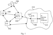
- Fig. 1 shows, by way of an example, a network architecture of communication system.
- a radio access architecture based on long term evolution advanced (LTE Advanced, LTE-A) or new radio (NR), also known as fifth generation (5G), without restricting the embodiments to such an architecture, however.
- LTE Advanced long term evolution advanced
- NR new radio
- 5G fifth generation
- UMTS universal mobile telecommunications system
- UTRAN radio access network
- LTE long term evolution
- WLAN wireless local area network
- WiFi worldwide interoperability for microwave access
- Bluetooth ® personal communications services
- PCS personal communications services
- WCDMA wideband code division multiple access
- UWB ultra-wideband
- IMS Internet Protocol multimedia subsystems
- Fig. 1 shows a part of an exemplifying radio access network.
- Fig. 1 shows user devices or user equipments (UEs) 100 and 102 configured to be in a wireless connection on one or more communication channels in a cell with an access node, such as gNB, i.e. next generation NodeB, or eNB, i.e. evolved NodeB (eNodeB), 104 providing the cell.
- an access node such as gNB, i.e. next generation NodeB, or eNB, i.e. evolved NodeB (eNodeB), 104 providing the cell.
- the physical link from a user device to the network node is called uplink (UL) or reverse link and the physical link from the network node to the user device is called downlink (DL) or forward link.
- UL uplink
- DL downlink
- network nodes or their functionalities may be implemented by using any node, host, server or access point etc. entity suitable for such a usage.
- a communications system typically comprises more than one network node in which case the network nodes may also be configured to communicate with one another over links, wired or wireless, designed for the purpose. These links may be used for signalling purposes.
- the network node is a computing device configured to control the radio resources of the communication system it is coupled to.
- the network node may also be referred to as a base station (BS), an access point or any other type of interfacing device including a relay station capable of operating in a wireless environment.
- the network node includes or is coupled to transceivers. From the transceivers of the network node, a connection is provided to an antenna unit that establishes bi-directional radio links to user devices.
- the antenna unit may comprise a plurality of antennas or antenna elements.
- the network node is further connected to core network 110 (CN or next generation core NGC).
- core network 110 CN or next generation core NGC
- the counterpart on the CN side can be a serving gateway (S-GW, routing and forwarding user data packets), packet data network gateway (P-GW), for providing connectivity of user devices (UEs) to external packet data networks, or mobile management entity (MME), etc.
- S-GW serving gateway
- P-GW packet data network gateway
- MME mobile management entity
- An example of the network node configured to operate as a relay station is integrated access and backhaul node (IAB).
- the distributed unit (DU) part of the IAB node performs BS functionalities of the IAB node, while the backhaul connection is carried out by the mobile termination (MT) part of the IAB node.
- MT mobile termination
- UE functionalities may be carried out by IAB MT, and BS functionalities may be carried out by IAB DU.
- Network architecture may comprise a parent node, i.e. IAB donor, which may have wired connection with the CN, and wireless connection with the IAB MT.
- the user device typically refers to a portable computing device that includes wireless mobile communication devices operating with or without a subscriber identification module (SIM), including, but not limited to, the following types of devices: a mobile station (mobile phone), smartphone, personal digital assistant (PDA), handset, device using a wireless modem (alarm or measurement device, etc.), laptop and/or touch screen computer, tablet, game console, notebook, and multimedia device.
- SIM subscriber identification module
- a user device may also be a nearly exclusive uplink only device, of which an example is a camera or video camera loading images or video clips to a network.
- a user device may also be a device having capability to operate in Internet of Things (IoT) network which is a scenario in which objects are provided with the ability to transfer data over a network without requiring human-to-human or human-to-computer interaction.
- IoT Internet of Things
- apparatuses have been depicted as single entities, different units, processors and/or memory units (not all shown in Fig. 1 ) may be implemented inside these apparatuses, to enable the functioning thereof.
- 5G enables using multiple input - multiple output (MIMO) technology at both UE and gNB side, many more base stations or nodes than the LTE (a so-called small cell concept), including macro sites operating in co-operation with smaller stations and employing a variety of radio technologies depending on service needs, use cases and/or spectrum available.
- 5G mobile communications supports a wide range of use cases and related applications including video streaming, augmented reality, different ways of data sharing and various forms of machine type applications (such as (massive) machine-type communications (mMTC), including vehicular safety, different sensors and real-time control.
- 5G is expected to have multiple radio interfaces, namely below 7GHz, cmWave and mmWave, and also being integratable with existing legacy radio access technologies, such as the LTE.
- FR1 Below 7GHz frequency range may be called as FR1, and above 24GHz (or more exactly 24- 52.6 GHz) as FR2, respectively.
- Integration with the LTE may be implemented, at least in the early phase, as a system, where macro coverage is provided by the LTE and 5G radio interface access comes from small cells by aggregation to the LTE.
- 5G is planned to support both inter-RAT operability (such as LTE-5G) and inter-RI operability (inter-radio interface operability, such as below 7GHz - cmWave, below 7GHz - cmWave - mmWave).
- inter-RAT operability such as LTE-5G
- inter-RI operability inter-radio interface operability
- 5G networks is network slicing in which multiple independent and dedicated virtual sub-networks (network instances) may be created within the same infrastructure to run services that have different requirements on latency, reliability, throughput and mobility.
- the communication system is also able to communicate with other networks, such as a public switched telephone network or the Internet 112, or utilize services provided by them.
- the communication network may also be able to support the usage of cloud services, for example at least part of core network operations may be carried out as a cloud service (this is depicted in Fig. 1 by "cloud" 114).
- the communication system may also comprise a central control entity, or a like, providing facilities for networks of different operators to cooperate for example in spectrum sharing.
- Edge cloud may be brought into radio access network (RAN) by utilizing network function virtualization (NVF) and software defined networking (SDN).
- RAN radio access network
- NVF network function virtualization
- SDN software defined networking
- Using edge cloud may mean access node operations to be carried out, at least partly, in a server, host or node operationally coupled to a remote radio head or base station comprising radio parts. It is also possible that node operations will be distributed among a plurality of servers, nodes or hosts.
- Application of cloud RAN architecture enables RAN real time functions being carried out at the RAN side (in a distributed unit, DU 104) and non-real time functions being carried out in a centralized manner (in a centralized unit, CU 108).
- 5G may also utilize satellite communication to enhance or complement the coverage of 5G service, for example by providing backhauling.
- Possible use cases are providing service continuity for machine-to-machine (M2M) or Internet of Things (IoT) devices or for passengers on board of vehicles, or ensuring service availability for critical communications, and future railway/maritime/aeronautical communications.
- Satellite communication may utilise geostationary earth orbit (GEO) satellite systems, but also low earth orbit (LEO) satellite systems, in particular mega-constellations (systems in which hundreds of (nano)satellites are deployed).
- GEO geostationary earth orbit
- LEO low earth orbit
- Each satellite 106 in the constellation may cover several satellite-enabled network entities that create on-ground cells.
- the on-ground cells may be created through an on-ground relay node 104 or by a gNB located on-ground or in a satellite.
- the UEs may communicate with each other without involvement of a network node 104.
- sidelink communication is used for sending and receiving sidelink positioning reference signals (SL PRSs), and measurements on these signals may be used for positioning of UE.
- the measurements may be based on time of arrival (TooA), round trip time, angle of arrival / angle of departure (AoA/AoD), reference signal time difference (RSTD), for example.
- TOA time of arrival
- AoA/AoD angle of arrival / angle of departure
- RSTD reference signal time difference
- SSL positioning may provide absolute position or relative position of a UE, which may be referred to as a target UE.
- the anchor UE assists the target UE in positioning.
- absolute position is determined, the longitude and latitude coordinates of a UE are calculated. Coordinates of an anchor UE need to be known in absolute positioning.
- the UE may be a stationary UE or a moving UEs.
- Relative positioning may be also referred to as ranging. In relative positioning, it is not necessary to know the coordinates of the anchor UE.
- the resources may be dedicated resources and/or shared resources.
- a shared resource pool may be a resource pool that may be used for communication and positioning. It has been agreed that shared resources pool(s) are to be supported with backward compatibility. Shared resources may be used by legacy UEs (i.e., pre-Rel-18 UEs) and release 18 (Rel-18) UEs, and possibly by UEs that are configured according to subsequent releases of the same standards, for example.
- SL-RSRP layer 1 side link reference signal received power
- DMRS SL de-modulation reference signal
- a legacy UE which is configured to operate on shared resource pool, might not be able to receive SL positioning reference signals (SL PRSs), but it rather may try to avoid the SL PRS slots and/or to minimize the impact of the SL PRS on its own communication.
- SL PRSs SL positioning reference signals
- a legacy UE may rely on SL-RSRP measurements.
- Method(s) are provided to enable legacy UE to measure RSRP of the SL PRS despite not being able to measure the SL PRS itself, and to enable efficient use of resources.
- Fig. 2 shows, by way of example, a sidelink positioning session between entities.
- a UE e.g. anchor UE 210 or a first UE, may be involved in a SL positioning session with at least one target UE 220 or second UE.
- the target UE 220 may be, for example, configured to operate according to Rel-18.
- the anchor UE 210 is configured to transmit SL PRSs 240 to other UEs.
- the SL PRSs 240 may be transmitted on shared resources or may be transmitted on dedicated resources. Thus, in addition to the target UEs 220 using the SL PRSs 240 for positioning, there may be legacy UEs 230 configured to measure the RSRP of the SL PRS transmissions, for example.
- the SL PRS resource 240 may comprise at least one de-modulation reference signal, DMRS, symbol.
- the anchor UE 210 may use DMRS sequence generation to map the DMRS sequence inside the PRS sequence.
- the anchor UE 210 is configured to generate a sequence of SL PRS resource transmission 240, which comprises a SL PRS sequence 260 and a DMRS sequence 250.
- the sequence of SL PRS resource transmission 240 comprises a plurality of symbols 241, 242, 243, 244, e.g. 4 symbols.
- the sequence of SL PRS resource transmission 240 may sometimes be referred to as a full sequence.
- full sequence may refer to full PRS resource available or configured.
- Full sequence should be understood as an illustrative example to describe the SL PRS resource transmission's length in case DMRS symbol(s) are not transmitted or do not need to be transmitted.
- the SL PRS sequence to be transmitted may be of full length, wherein the full length is length that is set by available resource or it could be a configured value, e.g. a number of symbols.
- the SL PRS sequence 260 may thus not be of said full length as the DMRS symbol(s) occupy some of the SL PRS resource.
- the DMRS sequence 250 may comprise at least one symbol, e.g. symbol 241.
- the SL PRS sequence 260 may comprise one or more symbols. Said one or more symbols may be referred to as one or more PRS symbols or SL PRS symbols.
- the sequence 260 may comprise three (3) symbols, e.g. symbols 242, 243, 244.
- the generated and transmitted SL PRS resource 240 may comprise two or more SL PRS symbols (e.g. sequence 260 of three SL PRS symbols) and at least one DMRS symbol (e.g. sequence 250 of one DMRS symbol).
- the legacy UE 230 may measure the RSRP on the at least one DMRS symbol 241 of the SL PRS resource 240 to determine sensing information without affecting the legacy performance.
- Number of the symbols in the SL PRS sequence may be, for example, 1, 2, 3, 4, 6, 8 or 12.
- Number of the symbols in the DMRS sequence may be, for example, 1, 2, 4 or 6.
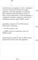
- Fig. 3 shows, by way of example, a flowchart of a method 300.
- the phases of the illustrated method may be performed by a UE, or by a control device configured to control the functioning thereof, when installed therein.
- the UE may be, for example, the anchor UE 210 of Fig. 2 , which is configured to perform at least the method 300.
- the method 300 comprises transmitting 310, by an apparatus (e.g. anchor UE 210), which is configured to perform sidelink positioning with another apparatus (e.g. target UE 220), to the other apparatus, an indication that a sidelink positioning reference signal, SL PRS, resource transmission, which the apparatus is configured to transmit, comprises at least one de-modulation reference signal, DMRS, symbol.
- an apparatus e.g. anchor UE 210
- another apparatus e.g. target UE 220
- an indication that a sidelink positioning reference signal, SL PRS, resource transmission which the apparatus is configured to transmit, comprises at least one de-modulation reference signal
- the method 300 comprises generating 320 a sequence of a SL PRS resource transmission comprising: a SL PRS sequence; and a DMRS sequence comprising at least one DMRS symbol.
- the method 300 comprises transmitting 330 the sequence of the SL PRS resource transmission at least to the other apparatus.
- the anchor UE 210 may transmit to the target UE 220 an indication that the UE 210 will use adaptive SL PRS sequence generation, or that the SL PRS resource, which the UE 210 is configured to transmit, comprises at least one DMRS symbol.
- the indication may be transmitted via SL PRS configuration or higher layer configuration, for example.
- the target UE 220 is made aware of that the SL PRS resource 240, which it will receive from the anchor UE 210, comprises at least one DMRS symbol.
- the SL PRS resource transmission may be generated in many ways.
- the UE 210 may generate a full sequence of the SL PRS resource, or in other words, the SL PRS resource of length of the full sequence.
- the full sequence comprises a plurality of symbols, e.g. 4 symbols as in Fig. 2 .
- the UE may generate the DMRS sequence 250 comprising at least one DMRS symbol, e.g. symbol 241.
- the UE may replace at least one symbol of the SL PRS sequence, having the length of the full sequence, by the DMRS sequence 250.
- the number of replaced symbols depends on the number of symbols in the DMRS sequence, which may be pre-configured or configured by the network.
- the resulting full sequence 240 comprises the SL PRS sequence 260 and the DMRS sequence 250.
- the UE may generate the DMRS sequence 250 of a first length in symbols, or having the first length measured in symbols.
- Length of the DMRS sequence may be, for example, 1 symbol.
- Length of the SL PRS sequence 260 e.g. a second length, may be determined or calculated by subtracting the first length from the length of the full sequence of the SL PRS resource. For example, if the full sequence is 4 symbols long, and the DMRS sequence 250 has 1 symbol, then the second length is 3 symbols. Then, the UE may combine the SL PRS sequence 260 and the DMRS sequence 250 to obtain the full sequence of the SL PRS resource.
- the resulting full sequence 240 comprises the SL PRS sequence 260 and the DMRS sequence 250.
- the UE may be made aware of the order of the symbols. For example, the anchor UE may transmit, to the target UE, an indication on a position of the at least one DMRS symbol in the full sequence of the SL PRS resource.
- the first symbol 241 may be configured as SL DMRS symbol.
- the legacy UE 230 may understand that the SL DMRS is in the same symbol as a physical sidelink shared channel (PSSCH) transmission, even it is not able to read SL PRS.
- PSSCH physical sidelink shared channel
- the legacy UE 230 may assume that the DMRS is in a given symbol on a slot or sub-slot, which is reserved.
- the first symbol may be configured as SL PRS symbol to another Rel-18 UE (e.g., target UE 220).
- the target UE 220 e.g. release 18 UE, may know that the DMRS symbol is included in the SL PRS sequence.
- the SL PRS sequence may be generated, for example, similar to a DL PRS generation formula defined in specification 38.211, version 17.4.0, in section 7.4.1.7.2.
- OFDM orthogonal frequency-division multiplexing
- the DMRS sequence may be generated, for example, based on SL DMRS sequence generation formula defined in specification 38.211, version 17.4.0, in section 8.4.1.1.1.
- the entire payload may be used to calculate the CRC parity bits.
- the parity bits by p 0 , p 1 , p 2 , p 3 , ... , p L -1 , where A is the payload size and L is the number of parity bits.
- the parity bits are computed with input bit sequence a 0 ′ , a 1 ′ , a 2 ′ , a 3 ′ , ... , a A + L ⁇ 1 ′ and attached by setting L to 24 bits and using the generator polynomial g CRC 24 C ( D ).
- the CRC parity bits are scrambled with the corresponding radio network temporary identifier, RNTI x rnti, 0 , x rnti, 1 , ... , x rnti, 15 , where x rnti, 0 corresponds to the most significant bit (MSB) of the RNTI, to form the sequence of bits c 0 , c 1 , c 2 , c 3 , ... , c K -1 .
- MSB most significant bit
- sequence generation of the SL DMRS and the SL PRS have different initializations, c_init.
- the DMRS sequence and the SL PRS sequence may be generated using same or similar sequence initialization equation.
- the DMRS sequence and the SL PRS sequence may be generated using the DMRS sequence initialization equation.
- a similar or the same SL PRS sequence is achieved as the current SL DMRS sequence for the symbols where the SL DMRS would be allocated if PSSCH was transmitted to the legacy UE.
- the Rel-18 UE is able to measure a SL-PRS RSRP from the whole sequence (DMRS symbols and SL PRS symbols).
- the legacy UE might not know that the DMRS symbols are configured among the SL PRS symbols, but may still perform RSRP measurement on the at least one DMRS symbol of the SL PRS resource.
- the anchor UE may use the DMRS sequence initialization equation to generate both the DMRS sequence and the SL PRS sequence.
- the initialization equation may use a first identity value, e.g. N ID X or N ID , as defined above for identity of the DMRS sequence.
- the initialization equation may use a second identity value.
- the first identity value is a different value than the second identity value.
- the first identity value and the second identity value are different values. Different identity values may be used in the initialization equation to randomize interference.
- the second identity value may be, for example, a parameter value configured by network, e.g. via higher layer signalling.
- the second identity value may be determined as a function of SL PRS identity (ID).
- ID SL PRS identity
- a configured second identity value be may equal to SL PRS ID.
- a configured second identity value may be selected as a randomly assigned value between 0 - 65536.
- a configured second identity value may be selected as a UE unique assigned value between 0 - 65536.
- a configured second identity value may be determined as a function of other UE IDs.
- the second identity value may follow a similar principle as other sidelink reference signals.
- N ID of CSI-RS may depend on the CRC for sidelink control information mapped to PSCCH associated with the CSI-RS.
- the UE may follow the DMRS configuration.
- the identity of the DMRS sequence may be used as an identity of the SL PRS sequence, where the identity of the DMRS sequence may be defined as N ID X or N ID .
- the UE 210 may transmit the full sequence of the SL PRS resource 240 on a shared resource pool.
- Fig. 4 shows, by way of example, a flowchart of a method 400.
- the phases of the illustrated method may be performed by a UE, or by a control device configured to control the functioning thereof, when installed therein.
- the UE may be, for example, the target UE 220 of Fig. 2 , which is configured to perform at least the method 400.
- the method comprises receiving 410, by an apparatus (e.g. the target UE 220), which is configured to perform sidelink positioning with another apparatus (e.g. the anchor UE 210), from the other apparatus, an indication that a sidelink positioning reference signal, SL PRS, resource transmission, which the apparatus is configured to receive, comprises at least one de-modulation reference signal, DMRS, symbol.
- the method 400 comprises receiving 420 the SL PRS resource transmission comprising: a SL PRS sequence; and a DMRS sequence comprising at least one DMRS symbol.
- the target UE receives the indication that the SL PRS resource transmission, which it will receive, comprises at least one DMRS symbol.
- the indication may be transmitted via SL PRS configuration or higher layer configuration, for example.
- the target UE may be aware of the order of the symbols. For example, the target UE may receive an indication on a position of the at least one DMRS symbol in the SL PRS resource transmission.
- the target UE understands the received SL PRS resource comprising the SL PRS sequence and the DMRS sequence.
- SL PRS sequence and the DMRS sequence are both pseudo-random sequences, and therefore, the change in the performance of the target UE is minimal compared to receiving a long SL PRS sequence without any DMRS symbols.
- the target UE may perform SL positioning measurement based on the received SL PRS resource.
- the target UE is able to employ the full sequence for positioning even though at least one symbol of the sequence is a DMRS symbol.
- the target UE may combine the received DMRS sequence with the received SL PRS sequence to a combined SL PRS sequence.
- the target UE may determine its position based on the combined SL PRS sequence.
- the target UE may generate a local copy of a reference SL PRS sequence before performing cross-correlation (or other positioning measurement processing) between the reference signal and the received SL PRS, and include the DMRS sequence as part of the overall local copy.
- the target UE may utilize information on the initialization equation and information on the identity values used, by the anchor UE, in generating the sequences.
- the target UE may acquire information on the identity values similarly as the anchor UE.
- the method(s) as disclosed herein provide improved SL positioning sensing for resource reservation, reduced SL PRS interference, backwards compatible design, and efficient use of sidelink control information (SCI) bits or resources.
- SL PRS interference may be reduced compared to configuring SL PRS sequence and DMRS sequence, which are different from each other, on the same symbols.
- Fig. 5 shows, by way of example, an apparatus capable of performing the method(s) as disclosed herein.
- device 500 which may comprise, for example, a user equipment, such as an anchor UE 210 of Fig. 2 , or a target UE 220 of Fig. 2 .
- processor 510 which may comprise, for example, a single- or multi-core processor wherein a single-core processor comprises one processing core and a multi-core processor comprises more than one processing core.
- Processor 510 may comprise, in general, a control device.
- Processor 510 may comprise more than one processor.
- Processor 510 may be a control device.
- Processor 510 may comprise at least one application-specific integrated circuit, ASIC.
- Processor 510 may comprise at least one field-programmable gate array, FPGA.
- Processor 510 may be means for performing method steps in device 500.
- Processor 510 may be configured, at least in part by computer instructions, to perform actions.
- a processor may comprise circuitry, or be constituted as circuitry or circuitries, the circuitry or circuitries being configured to perform phases of methods in accordance with example embodiments described herein.
- circuitry may refer to one or more or all of the following: (a) hardware-only circuit implementations, such as implementations in only analog and/or digital circuitry, and (b) combinations of hardware circuits and software, such as, as applicable: (i) a combination of analog and/or digital hardware circuit(s) with software/firmware and (ii) any portions of hardware processor(s) with software (including digital signal processor(s)), software, and memory(ies) that work together to cause an apparatus, such as a user equipment, to perform various functions) and (c) hardware circuit(s) and or processor(s), such as a microprocessor(s) or a portion of a microprocessor(s), that requires software (e.g., firmware) for operation, but the software may not be present when it is not needed for operation.
- firmware firmware
- circuitry also covers an implementation of merely a hardware circuit or processor (or multiple processors) or portion of a hardware circuit or processor and its (or their) accompanying software and/or firmware.
- circuitry also covers, for example and if applicable to the particular claim element, a baseband integrated circuit or processor integrated circuit for a mobile device or a similar integrated circuit in server, a cellular network device, or other computing or network device.
- Device 500 may comprise memory 520.
- Memory 520 may comprise random-access memory and/or permanent memory.
- Memory 520 may comprise at least one RAM chip.
- Memory 520 may comprise solid-state, magnetic, optical and/or holographic memory, for example.
- Memory 520 may be at least in part accessible to processor 510.
- Memory 520 may be at least in part comprised in processor 510.
- Memory 520 may be means for storing information.
- Memory 520 may comprise instructions, such as computer instructions or computer program code, that processor 510 is configured to execute. When instructions configured to cause processor 510 to perform certain actions are stored in memory 520, and device 500 overall is configured to run under the direction of processor 510 using instructions from memory 520, processor 510 and/or its at least one processing core may be considered to be configured to perform said certain actions.
- Memory 520 may be at least in part external to device 500 but accessible to device 500.
- Device 500 may comprise a transmitter 530.
- Device 500 may comprise a receiver 540.
- Transmitter 530 and receiver 540 may be configured to transmit and receive, respectively, information in accordance with at least one cellular or non-cellular standard.
- Transmitter 530 may comprise more than one transmitter.
- Receiver 540 may comprise more than one receiver.
- Transmitter 530 and/or receiver 540 may be configured to operate in accordance with global system for mobile communication, GSM, wideband code division multiple access, WCDMA, 5G, long term evolution, LTE, IS-95, wireless local area network, WLAN, Ethernet and/or worldwide interoperability for microwave access, WiMAX, standards, for example.
- Device 500 may comprise a near-field communication, NFC, transceiver 550.
- NFC transceiver 550 may support at least one NFC technology, such as NFC, Bluetooth, Wibree or similar technologies.
- Device 500 may comprise user interface, UI, 560.
- UI 560 may comprise at least one of a display, a keyboard, a touchscreen, a vibrator arranged to signal to a user by causing device 500 to vibrate, a speaker and a microphone.
- a user may be able to operate device 500 via UI 560, for example to accept incoming telephone calls, to originate telephone calls or video calls, to browse the Internet, to manage digital files stored in memory 520 or on a cloud accessible via transmitter 530 and receiver 540, or via NFC transceiver 550, and/or to play games.
- Processor 510 may be furnished with a transmitter arranged to output information from processor 510, via electrical leads internal to device 500, to other devices comprised in device 500.
- a transmitter may comprise a serial bus transmitter arranged to, for example, output information via at least one electrical lead to memory 520 for storage therein.
- the transmitter may comprise a parallel bus transmitter.
- processor 510 may comprise a receiver arranged to receive information in processor 510, via electrical leads internal to device 500, from other devices comprised in device 500.
- Such a receiver may comprise a serial bus receiver arranged to, for example, receive information via at least one electrical lead from receiver 540 for processing in processor 510.
- the receiver may comprise a parallel bus receiver.
- Processor 510, memory 520, transmitter 530, receiver 540, NFC transceiver 550, UI 560 may be interconnected by electrical leads internal to device 500 in a multitude of different ways.
- each of the aforementioned devices may be separately connected to a master bus internal to device 500, to allow for the devices to exchange information.
- this is only one example and depending on the embodiment various ways of interconnecting at least two of the aforementioned devices may be selected.
- an apparatus comprising means for transmitting, to another apparatus, an indication that a sidelink positioning reference signal (SL PRS) resource transmission, which the apparatus is configured to transmit, comprises at least one de-modulation reference signal (DMRS) symbol; and generating a sequence of a SL PRS resource transmission comprising: a SL PRS sequence; and a DMRS sequence comprising at least one DMRS symbol; and transmitting the sequence of the SL PRS resource transmission at least to said another apparatus.
- S PRS sidelink positioning reference signal
- DMRS de-modulation reference signal
- the means may be further configured to cause performance of any steps described with reference to the apparatus.
- an apparatus comprising means for receiving, from another apparatus, an indication that a sidelink positioning reference signal, (SL PRS) resource transmission, which the apparatus is configured to receive, comprises at least one de-modulation reference signal (DMRS) symbol; and receiving, from said another apparatus, the SL PRS resource transmission comprising: a SL PRS sequence; and a DMRS sequence comprising at least one DMRS symbol.
- S PRS sidelink positioning reference signal
- DMRS de-modulation reference signal
- the means may be further configured to cause performance of any steps described with reference to the apparatus.
- non-transitory is a limitation of the medium itself (i.e., tangible, not a signal) as opposed to a limitation on data storage persistency (e.g., RAM vs. ROM).
Landscapes
- Engineering & Computer Science (AREA)
- Signal Processing (AREA)
- Computer Networks & Wireless Communication (AREA)
- Mobile Radio Communication Systems (AREA)
Applications Claiming Priority (1)
| Application Number | Priority Date | Filing Date | Title |
|---|---|---|---|
| FI20235160 | 2023-02-15 |
Publications (1)
| Publication Number | Publication Date |
|---|---|
| EP4418592A1 true EP4418592A1 (fr) | 2024-08-21 |
Family
ID=89661322
Family Applications (1)
| Application Number | Title | Priority Date | Filing Date |
|---|---|---|---|
| EP24152559.1A Pending EP4418592A1 (fr) | 2023-02-15 | 2024-01-18 | Génération d'une séquence de ressources de signal de référence de positionnement de liaison latérale |
Country Status (2)
| Country | Link |
|---|---|
| US (1) | US20240276428A1 (fr) |
| EP (1) | EP4418592A1 (fr) |
Families Citing this family (1)
| Publication number | Priority date | Publication date | Assignee | Title |
|---|---|---|---|---|
| US20240283601A1 (en) * | 2023-02-16 | 2024-08-22 | Qualcomm Incorporated | Structure of resource pool dedicated to sidelink positioning reference signals (sl-prs) |
Citations (1)
| Publication number | Priority date | Publication date | Assignee | Title |
|---|---|---|---|---|
| WO2023011347A1 (fr) * | 2021-08-02 | 2023-02-09 | 大唐高鸿智联科技(重庆)有限公司 | Appareil et procédé d'envoi de signal de référence de positionnement de liaison latérale, et appareil et procédé de réception de signal de référence de positionnement de liaison latérale |
-
2024
- 2024-01-18 EP EP24152559.1A patent/EP4418592A1/fr active Pending
- 2024-02-12 US US18/438,971 patent/US20240276428A1/en active Pending
Patent Citations (1)
| Publication number | Priority date | Publication date | Assignee | Title |
|---|---|---|---|---|
| WO2023011347A1 (fr) * | 2021-08-02 | 2023-02-09 | 大唐高鸿智联科技(重庆)有限公司 | Appareil et procédé d'envoi de signal de référence de positionnement de liaison latérale, et appareil et procédé de réception de signal de référence de positionnement de liaison latérale |
Non-Patent Citations (4)
| Title |
|---|
| APPLE INC: "Discussions on Potential solutions for SL positioning", vol. RAN WG1, no. e-Meeting; 20221010 - 20221019, 30 September 2022 (2022-09-30), XP052259062, Retrieved from the Internet <URL:https://ftp.3gpp.org/tsg_ran/WG1_RL1/TSGR1_110b-e/Docs/R1-2209589.zip R1-2209589 Discussions on Potential solutions for Sidelink positioning.docx> [retrieved on 20220930] * |
| OPPO: "Discussion on potential solutions for SL positioning", vol. 3GPP RAN 1, no. Toulouse, FR; 20221114 - 20221118, 7 November 2022 (2022-11-07), XP052222011, Retrieved from the Internet <URL:https://www.3gpp.org/ftp/TSG_RAN/WG1_RL1/TSGR1_111/Docs/R1-2211447.zip R1-2211447_OPPO_solution for SL Pos.docx> [retrieved on 20221107] * |
| OPPO: "Discussion on potential solutions for SL positioning", vol. RAN WG1, no. Toulouse, France; 20220822 - 20220826, 12 August 2022 (2022-08-12), XP052274222, Retrieved from the Internet <URL:https://ftp.3gpp.org/tsg_ran/WG1_RL1/TSGR1_110/Docs/R1-2206289.zip R1-2206289_OPPO_solution for SL Pos.docx> [retrieved on 20220812] * |
| QUALCOMM INCORPORATED: "Potential Solutions for Sidelink Positioning", vol. 3GPP RAN 1, no. Toulouse, FR; 20221114 - 20221118, 5 November 2022 (2022-11-05), XP052222685, Retrieved from the Internet <URL:https://www.3gpp.org/ftp/TSG_RAN/WG1_RL1/TSGR1_111/Docs/R1-2212122.zip R1-2212122 SL Solutions.docx> [retrieved on 20221105] * |
Also Published As
| Publication number | Publication date |
|---|---|
| US20240276428A1 (en) | 2024-08-15 |
Similar Documents
| Publication | Publication Date | Title |
|---|---|---|
| US12052690B2 (en) | Determining radar allocation in wireless communication system | |
| US12316569B2 (en) | Allocation of tracking reference signals | |
| US12108439B2 (en) | Radar operation of wireless device in wireless communication system | |
| US12574894B2 (en) | Signalling framework for virtual transmission-reception point localization in wireless networks | |
| US20250088325A1 (en) | Configuration of sidelink reference signals | |
| US20250168893A1 (en) | Configuration of random access channel resources | |
| EP4418592A1 (fr) | Génération d'une séquence de ressources de signal de référence de positionnement de liaison latérale | |
| EP4070590B1 (fr) | Synchronisation d'un dispositif terminal à une horloge réseau | |
| US20250047435A1 (en) | Conflict avoidance for reference signal | |
| US20240172247A1 (en) | Resource allocation for sidelink communication | |
| US20240322974A1 (en) | Apparatus, methods, and computer programs | |
| US12553981B2 (en) | Device positioning | |
| CN116158040B (zh) | 信道传输的方法、终端设备和网络设备 | |
| US20240155617A1 (en) | Method for reporting capability or incapability of a user equipment | |
| US20250337472A1 (en) | Apparatus and method for selecting an odd number of antenna ports for sounding reference signal resource transmission | |
| US12324004B2 (en) | Efficient signaling of sidelink radio resources | |
| US20240396693A1 (en) | Detection of a control resource set in a communication network | |
| US20240089034A1 (en) | Determining message repetitions in telecommunication systems | |
| WO2025229250A1 (fr) | Configuration de ressource de signal de référence de sondage de liaison montante pour un nombre impair de ports d'antenne |
Legal Events
| Date | Code | Title | Description |
|---|---|---|---|
| PUAI | Public reference made under article 153(3) epc to a published international application that has entered the european phase |
Free format text: ORIGINAL CODE: 0009012 |
|
| STAA | Information on the status of an ep patent application or granted ep patent |
Free format text: STATUS: THE APPLICATION HAS BEEN PUBLISHED |
|
| AK | Designated contracting states |
Kind code of ref document: A1 Designated state(s): AL AT BE BG CH CY CZ DE DK EE ES FI FR GB GR HR HU IE IS IT LI LT LU LV MC ME MK MT NL NO PL PT RO RS SE SI SK SM TR |
|
| STAA | Information on the status of an ep patent application or granted ep patent |
Free format text: STATUS: REQUEST FOR EXAMINATION WAS MADE |
|
| 17P | Request for examination filed |
Effective date: 20250220 |