EP4418618B1 - Verfahren zum betreiben eines kundenendgerätes mit breitband-gateway - Google Patents
Verfahren zum betreiben eines kundenendgerätes mit breitband-gateway Download PDFInfo
- Publication number
- EP4418618B1 EP4418618B1 EP23157577.0A EP23157577A EP4418618B1 EP 4418618 B1 EP4418618 B1 EP 4418618B1 EP 23157577 A EP23157577 A EP 23157577A EP 4418618 B1 EP4418618 B1 EP 4418618B1
- Authority
- EP
- European Patent Office
- Prior art keywords
- customer premises
- functionality
- premises equipment
- entity
- network
- Prior art date
- Legal status (The legal status is an assumption and is not a legal conclusion. Google has not performed a legal analysis and makes no representation as to the accuracy of the status listed.)
- Active
Links
Images
Classifications
-
- H—ELECTRICITY
- H04—ELECTRIC COMMUNICATION TECHNIQUE
- H04L—TRANSMISSION OF DIGITAL INFORMATION, e.g. TELEGRAPHIC COMMUNICATION
- H04L61/00—Network arrangements, protocols or services for addressing or naming
- H04L61/50—Address allocation
- H04L61/5007—Internet protocol [IP] addresses
- H04L61/5014—Internet protocol [IP] addresses using dynamic host configuration protocol [DHCP] or bootstrap protocol [BOOTP]
-
- H—ELECTRICITY
- H04—ELECTRIC COMMUNICATION TECHNIQUE
- H04L—TRANSMISSION OF DIGITAL INFORMATION, e.g. TELEGRAPHIC COMMUNICATION
- H04L41/00—Arrangements for maintenance, administration or management of data switching networks, e.g. of packet switching networks
- H04L41/50—Network service management, e.g. ensuring proper service fulfilment according to agreements
- H04L41/5061—Network service management, e.g. ensuring proper service fulfilment according to agreements characterised by the interaction between service providers and their network customers, e.g. customer relationship management
- H04L41/5064—Customer relationship management
-
- H—ELECTRICITY
- H04—ELECTRIC COMMUNICATION TECHNIQUE
- H04L—TRANSMISSION OF DIGITAL INFORMATION, e.g. TELEGRAPHIC COMMUNICATION
- H04L63/00—Network architectures or network communication protocols for network security
- H04L63/02—Network architectures or network communication protocols for network security for separating internal from external traffic, e.g. firewalls
- H04L63/0272—Virtual private networks
-
- H—ELECTRICITY
- H04—ELECTRIC COMMUNICATION TECHNIQUE
- H04L—TRANSMISSION OF DIGITAL INFORMATION, e.g. TELEGRAPHIC COMMUNICATION
- H04L2101/00—Indexing scheme associated with group H04L61/00
- H04L2101/60—Types of network addresses
- H04L2101/618—Details of network addresses
- H04L2101/659—Internet protocol version 6 [IPv6] addresses
-
- H—ELECTRICITY
- H04—ELECTRIC COMMUNICATION TECHNIQUE
- H04L—TRANSMISSION OF DIGITAL INFORMATION, e.g. TELEGRAPHIC COMMUNICATION
- H04L41/00—Arrangements for maintenance, administration or management of data switching networks, e.g. of packet switching networks
- H04L41/08—Configuration management of networks or network elements
- H04L41/0894—Policy-based network configuration management
-
- H—ELECTRICITY
- H04—ELECTRIC COMMUNICATION TECHNIQUE
- H04L—TRANSMISSION OF DIGITAL INFORMATION, e.g. TELEGRAPHIC COMMUNICATION
- H04L41/00—Arrangements for maintenance, administration or management of data switching networks, e.g. of packet switching networks
- H04L41/32—Specific management aspects for broadband networks
-
- H—ELECTRICITY
- H04—ELECTRIC COMMUNICATION TECHNIQUE
- H04L—TRANSMISSION OF DIGITAL INFORMATION, e.g. TELEGRAPHIC COMMUNICATION
- H04L61/00—Network arrangements, protocols or services for addressing or naming
- H04L61/45—Network directories; Name-to-address mapping
- H04L61/4505—Network directories; Name-to-address mapping using standardised directories; using standardised directory access protocols
- H04L61/4511—Network directories; Name-to-address mapping using standardised directories; using standardised directory access protocols using domain name system [DNS]
Definitions
- the present invention relates a method for operating a customer premises equipment with a broadband access network of a telecommunications network, wherein the broadband access network comprises at least one access node, wherein a specific access node of the broadband access network is enabled to operatively connect the customer premises equipment to the telecommunications network in view of providing communication services and/or communication access services to a user related or connected to the customer premises equipment, wherein the broadband access network comprises a service edge entity or functionality and a policy controller entity or functionality as well as a business support system entity or functionality.
- the present invention relates to a system comprising a customer premises equipment and a broadband access network for operating the customer premises equipment with the broadband access network, wherein the broadband access network comprises at least one access node, wherein a specific access node of the broadband access network is enabled to operatively connect the customer premises equipment to a telecommunications network in view of providing communication services and/or communication access services to a user related or connected to the customer premises equipment, wherein the broadband access network comprises a service edge entity or functionality and a policy controller entity or functionality as well as a business support system entity or functionality.
- the present invention relates to a program and to a computer-readable medium for operating a customer premises equipment with a broadband access network of a telecommunications network.
- providing a customer or subscriber with operational communication services typically requires a contractual relationship between such customer or subscriber and a network operator or service provider, i.e. especially being provided with fixed line connectivity implies such a contractual relationship to be established first and before the customer receives such connectivity.
- the customer receives a username and password or is provided with a line ID information (especially in case a broadband network gateway platform, BNG platform, is used) assigned to the connection.
- a line ID information especially in case a broadband network gateway platform, BNG platform, is used
- Such pieces of information are then transmitted to the broadband network gateway or other controlling instance (e.g. PFS), especially via PADI (IA) or DHCP discovery in TLV2.
- US 2022/0141176 A1 describes device identification based on a device identifier, device authentication, and subsequent allocation of an IP address to the device.
- EP 3 322 147 B1 describes an identification process based on a line ID
- WO 2011/160813 A1 describes a method in which a network access related ID such as a line ID is used to activate IP connectivity towards a walled garden environment, and where full access to the network is unlocked after the access related ID is federated with contract information.
- An object of the present invention is to provide a technically simple, effective and cost effective solution for operating a customer premises equipment with a broadband access network of a telecommunications network, wherein an access node of the broadband access network is enabled to operatively connect the customer premises equipment to the telecommunications network in view of providing communication services and/or communication access services to a user related or connected to the customer premises equipment in case that the user and/or customer premises equipment is unknown to the telecommunications network or has previously not been connected to the telecommunications network.
- a further object of the present invention is to provide a corresponding system comprising a customer premises equipment and a broadband access network, and a corresponding program or computer-readable medium.
- the object of the present invention is achieved by a method according to claim 1.
- a contractual relationship in order to operatively use network connectivity and be provided with communication services
- a contractual relationship is able to be realized (or to be put into operation) in real time (and in a convenient and cost-effective manner, especially using in-band communication) and, especially, it is possible to operatively use such network connectivity using a client device that is especially locally connected to a customer premises equipment, and, especially, such a contractual relationship is able to be realized or concluded by means of only using the customer premises equipment or the customer premises equipment together with the client device, especially based on using personal and/or commercial unique identifier information such as of a (national or regional) identity card or of a credit card.
- the aim is to be able to operatively use a customer premises equipment (and, especially and typically, to use client devices being locally connected (at least mainly locally connected, even if not exclusively), e.g. in a small office or home office or private setting) in view of communication services provided to that customer premises equipment (and the associated client devices) using the broadband access network of the telecommunications network.
- client devices being locally connected (at least mainly locally connected, even if not exclusively), e.g. in a small office or home office or private setting) in view of communication services provided to that customer premises equipment (and the associated client devices) using the broadband access network of the telecommunications network.
- it is advantageously possible to achieve this aim without the effort of an in person visit to a physical location or point of sale (and neither a video ident procedure) and without a pre-existing contractual relationship with the chosen network operator or service provider using the broadband access network for providing their communication services, and especially without the need to use a specific type of hardware device as customer premises equipment.
- the broadband access network comprises at least one access node (but typically a plurality of such access nodes), and a specific access node (of such at least one or plurality of access nodes) is enabled to operatively connect the customer premises equipment to the telecommunications network in view of providing communication services and/or communication access services to a user (i.e. a client device) related or connected to the customer premises equipment.
- the broadband access network additionally comprises a service edge entity or functionality and a policy controller entity or functionality as well as a business support system entity or functionality.
- the customer premises equipment transmits (in a first step) a request to be connected to the broadband access network, via the specific access node, to the service edge entity or functionality and/or to the policy controller entity or functionality, thereby the specific access node also transmitting a line ID information related to the connection, or port, used by the customer premises equipment.
- the customer premises equipment receives, from the service edge entity or functionality and/or from the policy controller entity or functionality the line ID information, and, in a third step, the customer premises equipment initiates a protected data transmission tunnel to the business support system entity or functionality, wherein the data transmission tunnel is specific to the customer premises equipment, and wherein the line ID information as well as an identifier information, especially a hardware identifier information, relating to the (hardware of the) customer premises equipment, is transmitted, using the data transmission tunnel, to the business support system entity or functionality.
- these are the prerequisites for a prospective customer or prospective client (or subscriber) of the broadband access network or the telecommunications network to be able to initiate an operatively usable network connectivity using the respective customer premises equipment, especially and preferably solely (or, at least predominantly) using in-band communication via the customer premises equipment.
- conducting further required steps - in order to eventually operatively establish such connectivity, especially in a protected and secure manner - is possible to be performed based on or using the protected data transmission tunnel between the customer premises equipment and the business support system entity or functionality.
- such a protected data transmission tunnel is realized using data being unique to (or uniquely assigned to) the customer premises equipment (hardware), hence, by means of being specific to the customer premises equipment (hardware) used, providing an enhanced level of data security and/or confidentiality regarding the protected data transmission tunnel itself.
- the protected data transmission tunnel between the customer premises equipment and the business support system entity or functionality it is advantageously possible, according to the present invention - while conducting further steps in order to operatively provide network connectivity to the customer premises equipment and its connected client devices -, to also protect the transmission of additional identifier information, especially personal and/or commercial identity information and/or the line ID.
- the situation of a customer premises equipment being unknown to the telecommunications network or having previously not been connected to the telecommunications network especially occurs in case of a new customer premises equipment device of a new prospective customer or user of the broadband access network.
- a network port or access node or port of such an access node
- such an association is typically based on, or relates to, an identifier information related to the hardware device of the customer premises equipment, e.g. the serial number or a MAC address of the customer premises equipment.
- a user plane communication channel is able to be established, carrying the protected data transmission tunnel, between the customer premises equipment and the business support system entity or functionality, especially used for conducting subsequent steps in order to operatively provide network connectivity to the customer premises equipment and its connected client devices.
- the telecommunications network according to the present invention might be a fixed-line telecommunications network or a mobile communication network but could also have both aspects, i.e. parts of a fixed-line telecommunications network (or being a fixed-line telecommunications network in such parts) and parts of a mobile communication network (or being a mobile communication network in such parts); such networks are also known under the term fixed-mobile-convergence networks (FMC networks).
- FMC networks fixed-mobile-convergence networks
- the business support system entity or functionality comprises a legitimation gateway, wherein the protected data transmission tunnel is, in a first sub-step of the third step, initiated towards the legitimation gateway, wherein, in a second sub-step of the third step, the customer premises equipment transmits, using the protected data transmission tunnel, personal and/or commercial identity information as well as the line ID to the legitimation gateway.
- the customer premises equipment receives, prior to the second sub-step of the third step, the personal and/or commercial identity information using a data transmission interface, especially a near-field communication interface and/or a short-range communication interface, especially a Bluetooth interface, and/or a wireless local area network communication interface, wherein especially the personal and/or commercial identity information is received from an identity document device and/or a smartcard device and/or a mobile computing device or smart phone.
- a data transmission interface especially a near-field communication interface and/or a short-range communication interface, especially a Bluetooth interface, and/or a wireless local area network communication interface
- the customer premises equipment transmits the identifier information, relating to the customer premises equipment, wherein especially the identifier information relating to the customer premises equipment corresponds to a hardware address of the customer premises equipment, especially a medium access control, MAC, address.
- a hardware address of the customer premises equipment especially a medium access control, MAC, address.
- the customer premises equipment transmits a request, especially a DNS request, regarding the business support system entity or functionality and/or the legitimation gateway, and the customer premises equipment receives an information regarding the business support system entity or functionality and/or the legitimation gateway.
- the customer premises equipment is connected to the specific access node using one or a plurality out of the following
- the service edge entity or functionality and/or the policy controller entity or functionality provides an internet protocol connection to the customer premises equipment in view of realizing or providing to the customer premises equipment a walled garden functionality, especially connectivity to a domain name system entity or functionality.
- the present invention relates to a system according to claim 9.
- the present invention relates to a program according to claim 10 and to a computer-readable medium according to claim 11.
- first, second, third and the like in the description and in the claims are used for distinguishing between similar elements and not necessarily for describing a sequential or chronological order; this is especially the case for the terms “first step”, “second step”, etc. It is to be understood that the terms so used are interchangeable under appropriate circumstances and that the embodiments of the invention described herein are capable of operation in other sequences than described or illustrated herein.
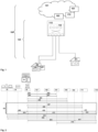
- a telecommunications network 100 is schematically shown, having - preferably - at least a fixed line part.
- a mobile (or cellular) part might be present as well, as part of the telecommunications network 100, but is not specifically illustrated in Figure 1 .
- User equipments or client devices 20, 20' are connected to the telecommunications network 100 by means of a (broadband) access network 120.
- the telecommunications network 100 preferably comprises (but not necessarily), especially as part of the broadband access network 120, at least one logical or physical central office point of delivery 110 that is preferably realized within a (mini) data center and that is especially handling different access requirements, especially different access possibilities, of the client devices 20, 20' to network functionalities provided by the telecommunications network 100 or via the telecommunications network 100.
- the telecommunications network 100 typically also comprises - besides the broadband access network 120 - a core network 101.
- the client devices 20, 20' are typically connected to the logical or physical central office point of delivery 110 by means of a customer premises equipment device 50 (e.g.
- the central office point of delivery 110 comprises a switching fabric 115 comprising a plurality of spine network nodes and typically also a plurality of leaf network nodes which are not explicitly represented in Figure 1 .
- the broadband access network 120 and/or the telecommunications network 100 furthermore comprises a business and/or operations support system 170 (or business support system 170).
- the broadband access network 120 and/or the telecommunications network 100 comprises a service edge entity or functionality 160 and a policy controller entity or functionality 161.
- FIG. 2 schematically illustrates a communication diagram between the customer premises equipment 50 as well as entities or functionalities of the broadband access network 120 and/or the telecommunications network 100 according to the present invention.
- These entities or functionalities of the broadband access network 120 and/or of the telecommunications network 100 include an access node (or, a specific access node) 151 to which the customer premises equipment 50 is connected to.
- these entities or functionalities of the broadband access network 120 and/or of the telecommunications network 100 include the service edge entity or functionality 160, the policy controller entity or functionality 161, a domain name system entity or functionality 165, an auto configuration server, ACS, 169, a legitimation gateway 171, and the business support system 170.
- the telecommunications network 100 might comprise an access node such as an optical line terminal (OLT), having a plurality of access (node) ports, wherein each one of these access ports is able to serve a plurality of customer premises equipments and the associated client devices.
- OLT optical line terminal
- a shared medium or a shared communication means, e.g.
- a point-to-multipoint access mechanism and especially a passive optical network or a part thereof or a data over cable service interface specification coaxial, DOCSIS, cable network is used between such a plurality of customer premises equipments, and the respective access node (or, rather, between these customer premises equipments, and the respective access node port of the access node).
- the telecommunications network 100 might additionally or alternatively comprises another access node, such as an MSAN, serving DSL customers.
- an MSAN access node typically comprises a plurality of access (node) ports. In contrast to the above mentioned access node using a shared medium, these access (node) ports are only able to serve one customer premises equipment (and the associated client devices).
- the mentioned access nodes are typically connected to a service edge (entity or functionality) 160 or broadband network gateway (entity or functionality), especially realized in or as part of a central office point of delivery 110, and the service edge (entity or functionality) 160 or broadband network gateway (entity or functionality) 160 is controlled by a policy server 161 or policy controller entity or functionality 161 (especially with an associated policy storage entity or functionality and/or an associated application programming interface, both not explicitly shown in Figures 1 and 2 ).
- the method relates to the operation of the customer premises equipment 50 (or a specific (one) customer premises equipment (of, typically, a plurality of customer premises equipments)) with the broadband access network 120 of the telecommunications network 100, the broadband access network 120 comprising typically a plurality of access nodes of the kind (or of another kind) of the specific access node 151; the specific access node 151 is enabled to operatively connect the (specific) customer premises equipment 50 to the telecommunications network 100 in view of providing communication services and/or communication access services to a user related or connected to the customer premises equipment 50 (i.e. especially a client device connected to that specific customer premises equipment 50).
- the broadband access network 120 comprises a service edge entity or functionality 160 and a policy controller entity or functionality 161 as well as a business support system entity or functionality 170, wherein, in case that the customer premises equipment 50 is unknown to the telecommunications network 100 or has previously not been connected to the telecommunications network 100, the method comprises the steps of:
- the business support system entity or functionality 170 comprises a legitimation gateway 171, wherein the protected data transmission tunnel 59 is, in a first sub-step of the third step, initiated towards the legitimation gateway 171, wherein, in a second sub-step of the third step, the customer premises equipment 50 transmits, using the protected data transmission tunnel 59, personal and/or commercial identity information as well as the line ID to the legitimation gateway 171.
- personal and/or commercial identity information might, e.g., comprise information or data as part of a national or regional identity card, or a credit card or another device comprising such personalized and/or protected data.
- an identity (document) device 55 e.g.
- a first processing step 401 the customer premises equipment 50 - after initially being connected to the access node 151, and typically also after having established a user plane communication channel using the access node 151 - transmits a PADI/DHCP discover message to the service edge entity or functionality 160, and the access node 151 thereby injects the line ID information related to the connection.
- the service edge entity or functionality 160 transmits a radius request (especially comprising the line ID information) to the policy controller entity or functionality 161.
- the first and second processing steps 401, 402 result in the customer premises equipment 50 transmitting a request (according to the first step of the inventive method) to be connected to the broadband access network 120, via the specific access node 151, to the service edge entity or functionality 160 and/or to the policy controller entity or functionality 161, wherein thereby the specific access node 151 also transmits the line ID information related to the connection, or port, used by the customer premises equipment 50.
- the policy controller entity or functionality 161 transmits a default profile including a DNS information (domain name system information) and the line ID information to the service edge entity or functionality 160.
- a fourth processing step 404 the service edge entity or functionality 160 transmits a PADO/DHCP offer message (via the access node 151) to the customer premises equipment 50.
- the third and fourth processing steps 403, 404 result in the customer premises equipment 50 receiving (according to the second step of the inventive method), from the service edge entity or functionality 160 and/or from the policy controller entity or functionality 161 the line ID information.
- the customer premises equipment 50 on the one hand, and the service edge entity or functionality 160 and/or the policy controller entity or functionality 161 on the other hand communicate using at least one out of the following:
- the customer premises equipment 50 receives, prior to the second sub-step of the third step, the personal and/or commercial identity information using the data transmission interface 54, especially a near-filed communication interface and/or a short-range communication interface, especially a Bluetooth interface, and/or a wireless local area network communication interface.
- the personal and/or commercial identity information is especially received from an identity document device 55 (or identity device 55) and/or a smartcard device 55 and/or a mobile computing device or smart phone.
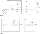
- FIG 3 another representation of the exchange of identifier information according to the present invention is schematically shown between the customer premises equipment 50 on the one hand, and the legitimation gateway 171 and/or the business support system entity or functionality 170 on the other hand.
- the customer premises equipment 50 especially a network ID module or entity or functionality 501 of the customer premises equipment 50 (i.e. the customer premises equipment 50 comprises such a network ID module or entity or functionality 501) - dials in to retrieve the line ID information (transmitted from the service edge entity or functionality 160 and/or from the policy controller entity or functionality 161 in the third and/or fourth processing steps 403, 404 shown in Figure 2 , but initially originating from the access node 151, cf.
- the network ID module or entity or functionality 501 of the customer premises equipment 50 extracts the line ID information and provides the line ID information to a tunnel client module or entity or functionality 502 as part of the customer premises equipment 50 (i.e. the customer premises equipment 50 comprises such a tunnel client module or entity or functionality 502).
- the tunnel client module or entity or functionality 502 retrieves (or receives) the hardware address of the customer premises equipment 50, i.e. the identifier information relating to the customer premises equipment 50, typically the MAC address or a serial number.
- first CID customer ID
- second CID customer ID
- client entity or functionality 504 of the customer premises equipment 50
- the customer premises equipment 50 comprises such a first CID client entity or functionality 503 and/or such a second CID client entity or functionality 504.
- the first CID (customer ID) client entity or functionality 503 realizes network/customer federation (federating the line ID information with an information relating to the customer premises equipment 50 and/or the client or customer (Pers.ID) - seventh processing step 607)
- the second CID (customer ID) client entity or functionality 504 realizes (or concludes) the contract between the client or customer (related to the customer premises equipment 50) and the telecommunications network or network operator (eighth processing step 608; this eighth processing step 608 especially being optional).
- Figure 4 schematically illustrates a representation regarding the protected data transmission tunnel 59 - especially its establishment and how it is operated - between the customer premises equipment 50 and the broadband access network 120 and/or an entity or functionality of the telecommunications network 100, especially the legitimation gateway 171, wherein the specific exemplary illustration of Figure 4 relates to a considered transmission - using the protected data transmission tunnel 59 - in the direction from the customer premises equipment 50 towards the legitimation gateway 171.
- the customer premises equipment 50 comprises, especially as part of the tunnel client module or entity or functionality 502, a payload scrambler 502', and the legitimation gateway 171 comprises a payload descrambler 171'.
- the protected data transmission tunnel 59 is established or set up and such a considered transmission occurs in the direction from the customer premises equipment 50 towards the legitimation gateway 171.
- Figure 4 exemplary shows, regarding such a situation, that the line ID information 151' (of the access node 151 used by the customer premises equipment 50) as well as the identifier information 50' relating to the customer premises equipment 50 is transmitted, by the customer premises equipment 50, and received by the legitimation gateway 171, in a protected manner (especially in an encrypted manner), i.e. the line ID information 151' and the identifier information 50' relating to the customer premises equipment 50 is not transmitted as plaintext (but as ciphertext, i.e.
- both the line ID information 151' as well as the identifier information 50' (relating to the customer premises equipment 50 - especially internally (of the customer premises equipment 50) detected or learned or retrieved, cf. the third processing step 603 represented in Figure 3 )
- the customer premises equipment 50 receives, prior to the second sub-step of the third step, the personal and/or commercial identity information using the data transmission interface 54 and/or the identity document device 55.
- the identity document device 55 could, alternatively or cumulatively, also be a user equipment (such as, e.g., a smart phone) or a computing device (such as, e.g., a tablet or the like).
- CPEs typical fixed network customer premises equipments
- G-PON access and/or P2P fiber access is usually already suitable for collecting this data and transmitting it during startup due to the technology used (i.e.
- the data transmission interface 54 Especially in case that the terminal device hardware address/modem ID/serial number (i.e. the identifier information 50' relating to the customer premises equipment 50) is also transmitted to the network, it is possible not only to realize federation (i.e. customer - connection federation) to be performed by (or in) the business support system entity or functionality 170, but the customer premises equipment 50 (or customer premises equipment device) can also be recognized and special features taken into account during automatic configuration - a prerequisite for such a functionality would be a default profile with an IP address and a comparatively low bandwidth.
- federation i.e. customer - connection federation
- a smartphone application collects the necessary data (such as, e.g., customer ID, device ID (i.e. the identifier information 50' relating to the customer premises equipment 50), connection ID (i.e. the line ID information 50')) and transmits such data via a mobile communication network (i.e.
- the necessary data are retrieved via (radio) near field technology, which is built (as the data transmission interface 54) into the fixed network customer premises equipment 50.
- the customer premises equipment 50 first establishes a default IP connection to the network to establish basic connectivity (first and second step or first to fourth processing steps 401 to 404 of Figure 2 ).
- the customer premises equipment 50 obtains the destination address of the business support system entity or functionality 170 system and/or the legitimization gateway 171 (and/or payment gateway) which provides the possibility to establish the protected data transmission tunnel 59 which may especially be encrypted (i.e. transports the transmitted data in encrypted manner).
- connection to the card reading function i.e. especially using the data transmission interface 54 of the customer premises equipment 50, e.g. to a mobile application (of a user equipment or smart phone device also having such an analogous data transmission interface) or to an additional device (such as an identity document device 55) is then established (cf. processing steps 409 to 414 of Figure 2 ).
- the customers legitimize themselves by transferring their data read out from the ID card and/or their cash card (credit, ).
- the ID card e.g. HW address of the terminal device, SN, ...), the ID card (ID card, cash card), all data for registration and, if necessary, also for concluding a contract are available.
- An initial plausibility check of the address determines whether the new customers are located (roughly) in the area of their (stated) place of residence, in which case activation takes place directly. If such check shows that the specified place of residence does not (roughly) match the area, activation takes place for a limited time, such that corresponding customers can connect to an agent for legitimation and thus put the connection into operation.
- the present invention it is advantageously possible to use automatic connection identification (by means of transmitting the line ID information 151' to the customer premises equipment 50 and then again, using the protected data transmission tunnel 59 towards the business support system entity or functionality 170 and/or legitimation gateway 171) for automatic connection set up.
- automatic connection identification is also generally applicable for hardware exchange of the customer premises equipment 50 and/or for relocation and/or for wholesale.
- the line ID information 151' is transmitted or transferred in (or as part of) the point-to-point-protocol connection to the customer premises equipment 50.
- the customer ID e.g.
- a specific set of data or a set of pieces of information is held in the customer premises equipment 50 (such a set of data or a set of pieces of information might relate to the connection (such as the line ID information), to customer data (such data identifying the user) and/or to the service profile / service profiles / applications), i.e. such a set of data or a set of pieces of information is held in a decentralized manner and not longer centered in the telecommunications network (e.g. on or at a repository such as the BNG/platform control) but managed by and agent (or module or component in the router, i.e. the customer premises equipment 50.
- a point-to-point-protocol (dial-up) connection is established without authentication, a secured data transmission tunnel is set up between the customer premises equipment 50 and the legitimation gateway 171 (or legitimation server, OTT); legitimation of the customer is performed, e.g. by means of an ID card as well as optional account information provided.
- legitimation gateway 171 or legitimation server, OTT
- legitimation of the customer is performed, e.g. by means of an ID card as well as optional account information provided.
- the customer establishes a contractual relationship and configures network access: Customer gets basic connectivity and legitimizes itself and controls network/service property.
Landscapes
- Engineering & Computer Science (AREA)
- Computer Networks & Wireless Communication (AREA)
- Signal Processing (AREA)
- Business, Economics & Management (AREA)
- General Business, Economics & Management (AREA)
- Computer Hardware Design (AREA)
- Computer Security & Cryptography (AREA)
- Computing Systems (AREA)
- General Engineering & Computer Science (AREA)
- Data Exchanges In Wide-Area Networks (AREA)
Claims (11)
- Verfahren zum Betreiben eines Teilnehmerendgerätes (50) mit einem Breitbandzugangsnetz (120) eines Telekommunikationsnetzes (100), wobei das Breitbandzugangsnetz (120) mindestens einen Zugangsknoten (151) umfasst, wobei ein spezifischer Zugangsknoten (151) des Breitbandzugangsnetzes (120) in die Lage versetzt wird, das Teilnehmerendgerät (50) mit dem Telekommunikationsnetz (100) wirkzuverbinden, um Kommunikationsdienste und/oder Kommunikationszugangsdienste für einen Benutzer bereitzustellen, der zu dem Teilnehmerendgerät (50) in Beziehung steht oder mit dem Teilnehmerendgerät (50) verbunden ist,wobei das Breitbandzugangsnetz (120) eine Service-Edge-Entität oder -Funktionalität (160) und eine Richtlinien-Controller-Entität oder -Funktionalität (161) sowie eine Business-Support-System-Entität oder -Funktionalität (170) umfasst,wobei in dem Fall, dass das Teilnehmerendgerät (50) dem Telekommunikationsnetz (100) unbekannt ist oder zuvor nicht mit dem Telekommunikationsnetz (100) verbunden war, das Verfahren die folgenden Schritte umfasst:- in einem ersten Schritt sendet das Teilnehmerendgerät (50) eine Anforderung, mit dem Breitbandzugangsnetz (120) verbunden zu werden, über den spezifischen Zugangsknoten (151) an die Service-Edge-Entität oder -Funktionalität (160) und/oder an die Richtlinien-Controller-Entität oder -Funktionalität (161), wobei dadurch der spezifische Zugangsknoten (151) auch eine Leitungskennungsinformation sendet, die sich auf die Verbindung oder den Port bezieht, die bzw. der durch das Teilnehmerendgerät (50) verwendet wird,- in einem zweiten Schritt empfängt das Teilnehmerendgerät (50) von der Service-Edge-Entität oder -Funktionalität (160) und/oder von der Richtlinien-Controller-Entität oder -Funktionalität (161) die Leitungskennungsinformation,- in einem dritten Schritt initiiert das Teilnehmerendgerät (50) einen geschützten Datenübertragungstunnel (59) zu der Business-Support-System-Entität oder -Funktionalität (170), wobei der Datenübertragungstunnel (59) für das Teilnehmerendgerät (50) spezifisch ist, und wobei die Leitungskennungsinformation sowie eine Identifiziererinformation, die sich auf das Teilnehmerendgerät (50) bezieht, unter Verwendung des Datenübertragungstunnels (59) zu der Business-Support-System-Entität oder -Funktionalität (170) übertragen werden.
- Verfahren nach Anspruch 1, wobei die Business-Support-System-Entität oder -Funktionalität (170) ein Legitimations-Gateway (171) umfasst, wobei der geschützte Datenübertragungstunnel (59) in einem ersten Teilschritt des dritten Schrittes in Richtung des Legitimations-Gateways (171) initiiert wird, wobei in einem zweiten Teilschritt des dritten Schrittes das Teilnehmerendgerät (50) unter Verwendung des geschützten Datenübertragungstunnels (59) persönliche und/oder gewerbliche Identitätsinformationen sowie die Leitungskennung an den Legitimations-Gateway (171) sendet.
- Verfahren nach einem der vorangehenden Ansprüche, wobei das Teilnehmerendgerät (50) vor dem zweiten Teilschritt des dritten Schrittes die persönlichen und/oder gewerblichen Identitätsinformationen unter Verwendung einer Datenübertragungsschnittstelle, insbesondere einer Nahfeldkommunikationsschnittstelle und/oder einer Kurzstreckenkommunikationsschnittstelle, wie zum Beispiel einer Bluetooth-Schnittstelle und/oder einer Wireless Local Area Network-Kommunikationsschnittstelle, empfängt,
wobei insbesondere die persönlichen und/oder gewerblichen Identitätsinformationen von einer Identitätsdokumentvorrichtung und/oder einer Smartcard-Vorrichtung (50) und/oder einer mobilen Computervorrichtung oder einem Smartphone empfangen werden. - Verfahren nach einem der vorangehenden Ansprüche, wobei während des ersten und des zweiten Schrittes das Teilnehmerendgerät (50) einerseits und die Service-Edge-Entität oder -Funktionalität (160) und/oder die Richtlinien-Controller-Entität oder -Funktionalität (161) andererseits unter Verwendung mindestens eines von Folgendem kommunizieren:- Point-to-Point-over-Ethernet-Protokoll (PPPoE), insbesondere unter Verwendung einer PPPoE Active Discovery Initiation (PADI)-Nachricht in dem ersten Schritt und einer PPPoE Active Discovery Offer (PADO)-Nachricht in dem zweiten Schritt,- Dynamic Host Configuration Protocol (DHCP), insbesondere unter Verwendung einer DHCP-Discover-Nachricht in dem ersten Schritt und einer DHCP-Offer-Nachricht in dem zweiten Schritt,- Dynamic Host Configuration Protocol (DHCPv6), insbesondere unter Verwendung einer DHCP-Router-Solicitation-Nachricht (RS) in dem ersten Schritt und eines DHCP-Router-Advertisement (RA) in dem zweiten Schritt.
- Verfahren nach einem der vorangehenden Ansprüche, wobei während des ersten und des zweiten Schrittes das Teilnehmerendgerät (50) die Identifiziererinformation, die sich auf das Teilnehmerendgerät (50) bezieht, sendet, wobei insbesondere die Identifiziererinformation, die sich auf das Teilnehmerendgerät (50) beziehen, einer Hardware-Adresse des Teilnehmerendgerätes (50), wie zum Beispiel einer Medium Access Control (MAC)-Adresse, entspricht.
- Verfahren nach einem der vorangehenden Ansprüche, wobei, nach dem zweiten Schritt und vor dem dritten Schritt, das Teilnehmerendgerät (50) eine Anfrage, insbesondere eine DNS-Anfrage, bezüglich der Business-Support-System-Entität oder -Funktionalität (170) und/oder des Legitimations-Gateways (171) sendet, und das Teilnehmerendgerät (50) eine Information bezüglich der Business-Support-System-Entität oder -Funktionalität (170) und/oder des Legitimations-Gateways (171) empfängt.
- Verfahren nach einem der vorangehenden Ansprüche, wobei das Teilnehmerendgerät (50) mit dem spezifischen Zugangsknoten (151) unter Verwendung eines oder mehrerer von Folgendem verbunden wird:- ein gemeinsam genutztes Medium, insbesondere ein Punkt-zu-Mehrpunkt-Zugangsmechanismus, wie zum Beispiel ein passives optisches Netz oder ein Teil davon oder ein Data Over Cable Service Interface Specification (DOCSIS)-Koaxialkabelnetz, wobei im Fall der Verwendung des passiven optischen Netzes oder eines Teils davon das Teilnehmerendgerät (50) insbesondere einem optischen Netzendgerät oder einer optischen Netzeinheit entspricht und der spezifische Zugangsknoten (151) insbesondere einem optischen Leitungsendgerät entspricht,- ein Punkt-zu-Punkt-Medium, insbesondere unter Verwendung eines Digital Subscriber Line (DSL)-Zugangsanschlusses und insbesondere unter Verwendung von Multi Service Access Node (MSAN)-Elementen.
- Verfahren nach einem der vorangehenden Ansprüche, wobei, insbesondere während des zweiten Schrittes, die Service-Edge-Entität oder -Funktionalität (160) und/oder die Richtlinien-Controller-Entität oder -Funktionalität (161) eine Internetprotokoll-Verbindung zu dem Teilnehmerendgerät (50) bereitstellen, um eine Walled-Garden-Funktionalität, insbesondere eine Konnektivität zu einer Domänennamensystem-Entität oder -Funktionalität (165), zu realisieren oder für das Teilnehmerendgerät (50) bereitzustellen.
- System, umfassend ein Teilnehmerendgerät (50) und ein Breitbandzugangsnetz (120), zum Betreiben des Teilnehmerendgerätes (50) mit dem Breitbandzugangsnetz (120), wobei das Breitbandzugangsnetz (120) mindestens einen Zugangsknoten (151) umfasst,wobei ein spezifischer Zugangsknoten (151) des Breitbandzugangsnetzes (120) in die Lage versetzt wird, das Teilnehmerendgerät (50) mit einem Telekommunikationsnetz (100) wirkzuverbinden, um Kommunikationsdienste und/oder Kommunikationszugangsdienste für einen Benutzer bereitzustellen, der zu dem Teilnehmerendgerät (50) in Beziehung steht oder mit dem Teilnehmerendgerät (50) verbunden ist,wobei das Breitbandzugangsnetz (120) eine Service-Edge-Entität oder -Funktionalität (160) und eine Richtlinien-Controller-Entität oder -Funktionalität (161) sowie eine Business-Support-System-Entität oder -Funktionalität (170) umfasst,wobei in dem Fall, dass das Teilnehmerendgerät (50) dem Telekommunikationsnetz (100) unbekannt ist oder zuvor nicht mit dem Telekommunikationsnetz (100) verbunden war, das System so konfiguriert ist, dass:- das Teilnehmerendgerät (50) eine Anforderung, mit dem Breitbandzugangsnetz (120) verbunden zu werden, über den spezifischen Zugangsknoten (151) an die Service-Edge-Entität oder -Funktionalität (160) und/oder an die Richtlinien-Controller-Entität oder -Funktionalität (161)sendet, wobei dadurch der spezifische Zugangsknoten (151) auch eine Leitungskennungsinformation sendet, die sich auf die Verbindung oder den Port bezieht, die bzw. der durch das Teilnehmerendgerät (50) verwendet wird,- das Teilnehmerendgerät (50) von der Service-Edge-Entität oder -Funktionalität (160) und/oder von der Richtlinien-Controller-Entität oder -Funktionalität (161) die Leitungskennungsinformation empfängt,- das Teilnehmerendgerät (50) einen geschützten Datenübertragungstunnel (59) zu der Business-Support-System-Entität oder -Funktionalität (170) initiiert, wobei der Datenübertragungstunnel (59) für das Teilnehmerendgerät (50) spezifisch ist, und wobei die Leitungskennungsinformation sowie eine Identifiziererinformation, die sich auf das Teilnehmerendgerät (50) bezieht, unter Verwendung des Datenübertragungstunnels (59) zu der Business-Support-System-Entität oder -Funktionalität (170) übertragen werden.
- Programm, umfassend einen computerlesbaren Programmcode, der, wenn er teilweise in einem Teilnehmerendgerät (50), teilweise in einer Service-Edge-Entität oder -Funktionalität (160) und/oder einer Richtlinien-Controller-Entität oder -Funktionalität (161) und teilweise in einer Business-Support-System-Entität oder -Funktionalität (170) ausgeführt wird, das Teilnehmerendgerät (50), die Service-Edge-Entität oder -Funktionalität (160) und/oder die Richtlinien-Controller-Entität oder -Funktionalität (161) und die Business-Support-System-Entität oder -Funktionalität (170) veranlasst, ein Verfahren nach einem der Ansprüche 1 bis 8 durchführen.
- Computerlesbares Medium, umfassend Instruktionen, die, wenn sie teilweise in einem Teilnehmerendgerät (50), teilweise in einer Service-Edge-Entität oder -Funktionalität (160) und/oder einer Richtlinien-Controller-Entität oder -Funktionalität (161) und teilweise in einer Business-Support-System-Entität oder -Funktionalität (170) ausgeführt werden, das Teilnehmerendgerät (50), die Service-Edge-Entität oder -Funktionalität (160) und/oder die Richtlinien-Controller-Entität oder -Funktionalität (161) und die Business-Support-System-Entität oder -Funktionalität (170) veranlassen, ein Verfahren nach einem der Ansprüche 1 bis 8 durchführen.
Priority Applications (3)
| Application Number | Priority Date | Filing Date | Title |
|---|---|---|---|
| ES23157577T ES3016459T3 (en) | 2023-02-20 | 2023-02-20 | Method for operating a customer premises equipment with a broadband access network |
| EP23157577.0A EP4418618B1 (de) | 2023-02-20 | 2023-02-20 | Verfahren zum betreiben eines kundenendgerätes mit breitband-gateway |
| PCT/EP2024/054092 WO2024175513A1 (en) | 2023-02-20 | 2024-02-18 | Method for operating a customer premises equipment with a broadband access network of a telecommunications network, wherein the broadband access network comprises at least one access node, system or broadband access network or telecommunications network, business support system entity or functionality or legitimation gateway or central office point of delivery, program and computer-readable medium |
Applications Claiming Priority (1)
| Application Number | Priority Date | Filing Date | Title |
|---|---|---|---|
| EP23157577.0A EP4418618B1 (de) | 2023-02-20 | 2023-02-20 | Verfahren zum betreiben eines kundenendgerätes mit breitband-gateway |
Publications (2)
| Publication Number | Publication Date |
|---|---|
| EP4418618A1 EP4418618A1 (de) | 2024-08-21 |
| EP4418618B1 true EP4418618B1 (de) | 2025-01-29 |
Family
ID=85321057
Family Applications (1)
| Application Number | Title | Priority Date | Filing Date |
|---|---|---|---|
| EP23157577.0A Active EP4418618B1 (de) | 2023-02-20 | 2023-02-20 | Verfahren zum betreiben eines kundenendgerätes mit breitband-gateway |
Country Status (3)
| Country | Link |
|---|---|
| EP (1) | EP4418618B1 (de) |
| ES (1) | ES3016459T3 (de) |
| WO (1) | WO2024175513A1 (de) |
Family Cites Families (3)
| Publication number | Priority date | Publication date | Assignee | Title |
|---|---|---|---|---|
| EP2583413A1 (de) * | 2010-06-21 | 2013-04-24 | Deutsche Telekom AG | Verfahren und system zur effizienten verwendung eines telekommunikationsnetzes und der verbindung zwischen dem telekommunikationsnetz und einem kundengerät |
| CN113225238B (zh) * | 2015-07-17 | 2022-08-26 | 华为技术有限公司 | 消息传输方法、接入节点、接入控制器及接入系统 |
| US11575649B2 (en) * | 2020-10-29 | 2023-02-07 | Juniper Networks, Inc. | Supporting dynamic host configuration protocol-based customer premises equipment in fifth generation wireline and wireless convergence |
-
2023
- 2023-02-20 EP EP23157577.0A patent/EP4418618B1/de active Active
- 2023-02-20 ES ES23157577T patent/ES3016459T3/es active Active
-
2024
- 2024-02-18 WO PCT/EP2024/054092 patent/WO2024175513A1/en not_active Ceased
Also Published As
| Publication number | Publication date |
|---|---|
| EP4418618A1 (de) | 2024-08-21 |
| ES3016459T3 (en) | 2025-05-09 |
| WO2024175513A1 (en) | 2024-08-29 |
Similar Documents
| Publication | Publication Date | Title |
|---|---|---|
| EP3639481B1 (de) | Verfahren und system zur einrichtung eines dienstpfades in einem kommunikationsnetzwerk | |
| EP1994674B1 (de) | Authentifizierung von mobilnetzanbietergeräten | |
| EP1575230B1 (de) | Server für routingverbindung mit einem clientgerät | |
| US9332579B2 (en) | Method and system for efficient use of a telecommunication network and the connection between the telecommunications network and a customer premises equipment | |
| US9036582B2 (en) | Method and system for efficient management of a telecommunications network and the connection between the telecommunications network and a customer premises equipment | |
| US20040168049A1 (en) | Method for encrypting data of an access virtual private network (VPN) | |
| US9413829B2 (en) | Method for efficient initialization of a telecommunications network and telecommunications network | |
| KR100661776B1 (ko) | 네트워크 접속 시스템 및 네트워크 접속 방법 | |
| CN113453098B (zh) | 一种宽带业务的管理方法及网络设备 | |
| EP2583411A1 (de) | Verfahren und system zur effizienten verwendung eines telekommunikationsnetzes und der verbindung zwischen dem telekommunikationsnetz und einem kundengerät | |
| WO2012099513A1 (en) | Service activation in a passive optical network (pon) | |
| KR101162290B1 (ko) | 서비스에 액세스를 위해 가상 네트워크에 액세스를 가능하게 하는 클라이언트에 대한 승인 방법 및 시스템 | |
| EP4418618B1 (de) | Verfahren zum betreiben eines kundenendgerätes mit breitband-gateway | |
| EP1791322B1 (de) | Verfahren und system zur automatischen verteilung der dienste an das ppp-zugriffsendgerät | |
| US20260128917A1 (en) | Operating a customer premises equipment with a broadband access network of a telecommunications network, wherein the broadband access network comprises at least one access node | |
| CN101365238B (zh) | 一种会话转换的方法及装置 | |
| EP4336777A1 (de) | Verfahren zum betrieb eines teilnehmergerätes mit breitbandzugang | |
| EP3793135B1 (de) | Verfahren zum verbesserten betrieb eines telekommunikationsnetzwerks, das als für multi-operator oder multi-provider aktiviertes netzwerk betriebene telekommunikationsnetzwerk, system, programm und computerlesbares medium | |
| US20090262738A1 (en) | Method for promptly redialing a broadband access server | |
| EP3633946B1 (de) | Verfahren und systeme zur zuordnung von teilnehmeridentifizierungsinformationen mit einem residential-gateway-identifikator | |
| EP3886532B1 (de) | Breitbandzugang für 5g-fähige heim-gateways | |
| JP2004040651A (ja) | 通信方法、通信装置、端末装置及び通信サービス提供サーバ | |
| JP2007226620A (ja) | 宅内ゲートウェイ装置およびネットワークシステムのアカウンティング管理方式 | |
| EP4102774A1 (de) | Verfahren zur bereitstellung einer festnetzbenutzervorrichtung | |
| JP2018142891A (ja) | インターネット接続処理方法 |
Legal Events
| Date | Code | Title | Description |
|---|---|---|---|
| PUAI | Public reference made under article 153(3) epc to a published international application that has entered the european phase |
Free format text: ORIGINAL CODE: 0009012 |
|
| STAA | Information on the status of an ep patent application or granted ep patent |
Free format text: STATUS: EXAMINATION IS IN PROGRESS |
|
| 17P | Request for examination filed |
Effective date: 20240130 |
|
| AK | Designated contracting states |
Kind code of ref document: A1 Designated state(s): AL AT BE BG CH CY CZ DE DK EE ES FI FR GB GR HR HU IE IS IT LI LT LU LV MC ME MK MT NL NO PL PT RO RS SE SI SK SM TR |
|
| REG | Reference to a national code |
Ref country code: DE Ref legal event code: R079 Free format text: PREVIOUS MAIN CLASS: H04L0041089400 Ipc: H04L0041506100 Ref document number: 602023001809 Country of ref document: DE |
|
| GRAP | Despatch of communication of intention to grant a patent |
Free format text: ORIGINAL CODE: EPIDOSNIGR1 |
|
| STAA | Information on the status of an ep patent application or granted ep patent |
Free format text: STATUS: GRANT OF PATENT IS INTENDED |
|
| RIC1 | Information provided on ipc code assigned before grant |
Ipc: H04L 61/5014 20220101ALI20240826BHEP Ipc: H04L 101/659 20220101ALI20240826BHEP Ipc: H04L 9/40 20220101ALI20240826BHEP Ipc: H04L 41/00 20220101ALI20240826BHEP Ipc: H04L 41/5061 20220101AFI20240826BHEP |
|
| INTG | Intention to grant announced |
Effective date: 20240911 |
|
| GRAS | Grant fee paid |
Free format text: ORIGINAL CODE: EPIDOSNIGR3 |
|
| GRAA | (expected) grant |
Free format text: ORIGINAL CODE: 0009210 |
|
| STAA | Information on the status of an ep patent application or granted ep patent |
Free format text: STATUS: THE PATENT HAS BEEN GRANTED |
|
| AK | Designated contracting states |
Kind code of ref document: B1 Designated state(s): AL AT BE BG CH CY CZ DE DK EE ES FI FR GB GR HR HU IE IS IT LI LT LU LV MC ME MK MT NL NO PL PT RO RS SE SI SK SM TR |
|
| REG | Reference to a national code |
Ref country code: GB Ref legal event code: FG4D |
|
| REG | Reference to a national code |
Ref country code: CH Ref legal event code: EP |
|
| REG | Reference to a national code |
Ref country code: DE Ref legal event code: R096 Ref document number: 602023001809 Country of ref document: DE |
|
| REG | Reference to a national code |
Ref country code: IE Ref legal event code: FG4D |
|
| PGFP | Annual fee paid to national office [announced via postgrant information from national office to epo] |
Ref country code: AT Payment date: 20250417 Year of fee payment: 3 |
|
| REG | Reference to a national code |
Ref country code: ES Ref legal event code: FG2A Ref document number: 3016459 Country of ref document: ES Kind code of ref document: T3 Effective date: 20250509 |
|
| REG | Reference to a national code |
Ref country code: NL Ref legal event code: MP Effective date: 20250129 |
|
| PG25 | Lapsed in a contracting state [announced via postgrant information from national office to epo] |
Ref country code: NL Free format text: LAPSE BECAUSE OF FAILURE TO SUBMIT A TRANSLATION OF THE DESCRIPTION OR TO PAY THE FEE WITHIN THE PRESCRIBED TIME-LIMIT Effective date: 20250129 |
|
| PG25 | Lapsed in a contracting state [announced via postgrant information from national office to epo] |
Ref country code: RS Free format text: LAPSE BECAUSE OF FAILURE TO SUBMIT A TRANSLATION OF THE DESCRIPTION OR TO PAY THE FEE WITHIN THE PRESCRIBED TIME-LIMIT Effective date: 20250429 |
|
| PG25 | Lapsed in a contracting state [announced via postgrant information from national office to epo] |
Ref country code: FI Free format text: LAPSE BECAUSE OF FAILURE TO SUBMIT A TRANSLATION OF THE DESCRIPTION OR TO PAY THE FEE WITHIN THE PRESCRIBED TIME-LIMIT Effective date: 20250129 |
|
| PG25 | Lapsed in a contracting state [announced via postgrant information from national office to epo] |
Ref country code: PL Free format text: LAPSE BECAUSE OF FAILURE TO SUBMIT A TRANSLATION OF THE DESCRIPTION OR TO PAY THE FEE WITHIN THE PRESCRIBED TIME-LIMIT Effective date: 20250129 |
|
| REG | Reference to a national code |
Ref country code: LT Ref legal event code: MG9D |
|
| PG25 | Lapsed in a contracting state [announced via postgrant information from national office to epo] |
Ref country code: NO Free format text: LAPSE BECAUSE OF FAILURE TO SUBMIT A TRANSLATION OF THE DESCRIPTION OR TO PAY THE FEE WITHIN THE PRESCRIBED TIME-LIMIT Effective date: 20250429 Ref country code: IS Free format text: LAPSE BECAUSE OF FAILURE TO SUBMIT A TRANSLATION OF THE DESCRIPTION OR TO PAY THE FEE WITHIN THE PRESCRIBED TIME-LIMIT Effective date: 20250529 |
|
| REG | Reference to a national code |
Ref country code: AT Ref legal event code: MK05 Ref document number: 1764543 Country of ref document: AT Kind code of ref document: T Effective date: 20250129 |
|
| PG25 | Lapsed in a contracting state [announced via postgrant information from national office to epo] |
Ref country code: HR Free format text: LAPSE BECAUSE OF FAILURE TO SUBMIT A TRANSLATION OF THE DESCRIPTION OR TO PAY THE FEE WITHIN THE PRESCRIBED TIME-LIMIT Effective date: 20250129 |
|
| PG25 | Lapsed in a contracting state [announced via postgrant information from national office to epo] |
Ref country code: LV Free format text: LAPSE BECAUSE OF FAILURE TO SUBMIT A TRANSLATION OF THE DESCRIPTION OR TO PAY THE FEE WITHIN THE PRESCRIBED TIME-LIMIT Effective date: 20250129 Ref country code: PT Free format text: LAPSE BECAUSE OF FAILURE TO SUBMIT A TRANSLATION OF THE DESCRIPTION OR TO PAY THE FEE WITHIN THE PRESCRIBED TIME-LIMIT Effective date: 20250529 |
|
| PG25 | Lapsed in a contracting state [announced via postgrant information from national office to epo] |
Ref country code: BG Free format text: LAPSE BECAUSE OF FAILURE TO SUBMIT A TRANSLATION OF THE DESCRIPTION OR TO PAY THE FEE WITHIN THE PRESCRIBED TIME-LIMIT Effective date: 20250129 Ref country code: GR Free format text: LAPSE BECAUSE OF FAILURE TO SUBMIT A TRANSLATION OF THE DESCRIPTION OR TO PAY THE FEE WITHIN THE PRESCRIBED TIME-LIMIT Effective date: 20250430 |
|
| PG25 | Lapsed in a contracting state [announced via postgrant information from national office to epo] |
Ref country code: AT Free format text: LAPSE BECAUSE OF FAILURE TO SUBMIT A TRANSLATION OF THE DESCRIPTION OR TO PAY THE FEE WITHIN THE PRESCRIBED TIME-LIMIT Effective date: 20250129 |
|
| PG25 | Lapsed in a contracting state [announced via postgrant information from national office to epo] |
Ref country code: SE Free format text: LAPSE BECAUSE OF FAILURE TO SUBMIT A TRANSLATION OF THE DESCRIPTION OR TO PAY THE FEE WITHIN THE PRESCRIBED TIME-LIMIT Effective date: 20250129 |
|
| PG25 | Lapsed in a contracting state [announced via postgrant information from national office to epo] |
Ref country code: SM Free format text: LAPSE BECAUSE OF FAILURE TO SUBMIT A TRANSLATION OF THE DESCRIPTION OR TO PAY THE FEE WITHIN THE PRESCRIBED TIME-LIMIT Effective date: 20250129 |
|
| PG25 | Lapsed in a contracting state [announced via postgrant information from national office to epo] |
Ref country code: DK Free format text: LAPSE BECAUSE OF FAILURE TO SUBMIT A TRANSLATION OF THE DESCRIPTION OR TO PAY THE FEE WITHIN THE PRESCRIBED TIME-LIMIT Effective date: 20250129 |
|
| PG25 | Lapsed in a contracting state [announced via postgrant information from national office to epo] |
Ref country code: MC Free format text: LAPSE BECAUSE OF FAILURE TO SUBMIT A TRANSLATION OF THE DESCRIPTION OR TO PAY THE FEE WITHIN THE PRESCRIBED TIME-LIMIT Effective date: 20250129 |
|
| PG25 | Lapsed in a contracting state [announced via postgrant information from national office to epo] |
Ref country code: LU Free format text: LAPSE BECAUSE OF NON-PAYMENT OF DUE FEES Effective date: 20250220 |
|
| PG25 | Lapsed in a contracting state [announced via postgrant information from national office to epo] |
Ref country code: EE Free format text: LAPSE BECAUSE OF FAILURE TO SUBMIT A TRANSLATION OF THE DESCRIPTION OR TO PAY THE FEE WITHIN THE PRESCRIBED TIME-LIMIT Effective date: 20250129 Ref country code: CZ Free format text: LAPSE BECAUSE OF FAILURE TO SUBMIT A TRANSLATION OF THE DESCRIPTION OR TO PAY THE FEE WITHIN THE PRESCRIBED TIME-LIMIT Effective date: 20250129 |
|
| PG25 | Lapsed in a contracting state [announced via postgrant information from national office to epo] |
Ref country code: RO Free format text: LAPSE BECAUSE OF FAILURE TO SUBMIT A TRANSLATION OF THE DESCRIPTION OR TO PAY THE FEE WITHIN THE PRESCRIBED TIME-LIMIT Effective date: 20250129 |
|
| PG25 | Lapsed in a contracting state [announced via postgrant information from national office to epo] |
Ref country code: SK Free format text: LAPSE BECAUSE OF FAILURE TO SUBMIT A TRANSLATION OF THE DESCRIPTION OR TO PAY THE FEE WITHIN THE PRESCRIBED TIME-LIMIT Effective date: 20250129 |
|
| REG | Reference to a national code |
Ref country code: DE Ref legal event code: R097 Ref document number: 602023001809 Country of ref document: DE |
|
| PLBE | No opposition filed within time limit |
Free format text: ORIGINAL CODE: 0009261 |
|
| STAA | Information on the status of an ep patent application or granted ep patent |
Free format text: STATUS: NO OPPOSITION FILED WITHIN TIME LIMIT |
|
| REG | Reference to a national code |
Ref country code: BE Ref legal event code: MM Effective date: 20250228 |
|
| 26N | No opposition filed |
Effective date: 20251030 |
|
| PG25 | Lapsed in a contracting state [announced via postgrant information from national office to epo] |
Ref country code: BE Free format text: LAPSE BECAUSE OF NON-PAYMENT OF DUE FEES Effective date: 20250228 |
|
| PG25 | Lapsed in a contracting state [announced via postgrant information from national office to epo] |
Ref country code: IE Free format text: LAPSE BECAUSE OF NON-PAYMENT OF DUE FEES Effective date: 20250220 |
|
| PGFP | Annual fee paid to national office [announced via postgrant information from national office to epo] |
Ref country code: ES Payment date: 20260319 Year of fee payment: 4 |
|
| PGFP | Annual fee paid to national office [announced via postgrant information from national office to epo] |
Ref country code: DE Payment date: 20260217 Year of fee payment: 4 |
|
| PGFP | Annual fee paid to national office [announced via postgrant information from national office to epo] |
Ref country code: IT Payment date: 20260228 Year of fee payment: 4 |
|
| PGFP | Annual fee paid to national office [announced via postgrant information from national office to epo] |
Ref country code: FR Payment date: 20260223 Year of fee payment: 4 |