EP4420557A1 - Modularer wagen zur lagerung von stallartikeln - Google Patents
Modularer wagen zur lagerung von stallartikeln Download PDFInfo
- Publication number
- EP4420557A1 EP4420557A1 EP23158395.6A EP23158395A EP4420557A1 EP 4420557 A1 EP4420557 A1 EP 4420557A1 EP 23158395 A EP23158395 A EP 23158395A EP 4420557 A1 EP4420557 A1 EP 4420557A1
- Authority
- EP
- European Patent Office
- Prior art keywords
- housing
- trolley
- perming
- handle
- machine
- Prior art date
- Legal status (The legal status is an assumption and is not a legal conclusion. Google has not performed a legal analysis and makes no representation as to the accuracy of the status listed.)
- Pending
Links
Images



Classifications
-
- A—HUMAN NECESSITIES
- A45—HAND OR TRAVELLING ARTICLES
- A45D—HAIRDRESSING OR SHAVING EQUIPMENT; EQUIPMENT FOR COSMETICS OR COSMETIC TREATMENTS, e.g. FOR MANICURING OR PEDICURING
- A45D44/00—Other cosmetic or toiletry articles, e.g. for hairdressers' rooms
- A45D44/02—Furniture or other equipment specially adapted for hairdressers' rooms and not covered elsewhere
-
- A—HUMAN NECESSITIES
- A45—HAND OR TRAVELLING ARTICLES
- A45D—HAIRDRESSING OR SHAVING EQUIPMENT; EQUIPMENT FOR COSMETICS OR COSMETIC TREATMENTS, e.g. FOR MANICURING OR PEDICURING
- A45D44/00—Other cosmetic or toiletry articles, e.g. for hairdressers' rooms
- A45D44/02—Furniture or other equipment specially adapted for hairdressers' rooms and not covered elsewhere
- A45D44/04—Special adaptations of portable frames or racks
Definitions
- the present disclosure relates, generally, to a trolley for storing salon items, and more particularly relates to a modular trolley adapted to removably store a perming machine.
- One aspect of the disclosure is to provide a modular trolley that can interchangeably support and store one or more hair dressing tool, for example, perming machine to enable hair dressing as well as transportation of various salon items.
- one or more hair dressing tool for example, perming machine to enable hair dressing as well as transportation of various salon items.
- One aspect of the disclosure is to provide a trolley to which a perming machine can be easily assembled/mounted.
- a trolley may include a housing having a plurality of walls and a plurality of drawers slidably coupled to the housing and including at least one drawer of the plurality of drawers removably coupled to the housing.
- the trolley further includes a mounting structure arranged along at least one of the plurality of the walls and configured to facilitate a removable mounting of a perming machine to the housing.
- the mounting structure is disposed at a location corresponding to a location of the removable drawer inside the housing.
- the at least one removable drawer is removed from the housing to arrange and mount the perming machine inside the housing.
- the removable drawer and the mounting structure enable a selective and removable attachment of the perming machine with the trolley.
- the removable drawer For mounting the perming machine to the housing, the removable drawer is completely removed from the housing and then perming machine is engaged and supported on the housing with the mounting structure. To again arrange the removable drawer inside the housing, the perming machine is removed and then the removable drawer is inserted inside the housing in place of the perming machine.
- the trolley acts as a modular trolley to which the components can be interchangeably mounted to facilitate storage of the salon items for transportation as well as hair dressing, for example, perming of the hairs.
- the plurality of walls may include a pair of sidewalls and the mounting structure includes at least one first hole extending through one of the pair of sidewalls and at least one second hole extending through other of the pair of sidewalls to enable coupling of the perming machine with the housing by a plurality of screws.
- the perming machine may include grooves that aligns with the first hole and the second hole and the screws extend through the grooves of the perming machine and the holes of the housing to enable mounting of the perming machine within the housing in place of the removable drawer.
- a rear wall and/or a top wall of the housing may include one or more hole as the mounting structure to enable mounting of the perming machine to the housing.
- the mounting structure includes a plurality of tabs extending inside the housing from at least one wall of the plurality of walls, and the perming machine may include a plurality of grooves to receive the tabs to enable engagement of the perming machine with the housing and retention of the perming machine within the housing.
- the plurality of walls includes a rear wall defining at least one opening disposed at a location corresponding to the location of the at least one removable drawer.
- One or more perming cables associated with one or more perming rods of the perming machine extends outwardly through the at least one opening of the rear wall when the perming machine is arranged inside the housing.
- the at least one opening includes a single opening having a substantially rectangular configuration and dimensions similar to the lateral dimensions of the perming machine to enable extension of plurality of perming cables outside the housing through the single opening.
- the housing includes a flap pivotally coupled to the rear wall of the housing and configured to cover the single large opening.
- a pivot axis of the flap extends along a breadth of the housing.
- the flap may be configured to move to a covering position under gravity to cover the opening and prevent any undesired falling off the salon item from the removable drawer through the opening.
- the flap may be a gate that pivots about a pivot axis that is substantially parallel to a height of the housing and, therefore, extends in a vertical direction. In such a case, the gate is moved between the open position and the cover position manually by a user.
- the at least one opening may include a plurality of openings to enable extension of the plurality of perming cable outside the housing. It may be appreciated that a single perming cable may extend through a single opening defined through the rear wall of the housing.
- the trolley further comprises a handle pivotally coupled to the housing and configured to pivot between a horizontal position and a vertical position relative to the housing. In the vertical position, the handle supports one or more cables of the perming machine.
- the handle is a rear handle extending rearwardly and outwardly of the rear wall of the housing in the horizontal position. In the horizontal position, the rear handle facilitates a pulling or pushing of the trolley.
- the trolley may comprise another handle, for example, a front handle, connected to the housing and extending forwardly of the front end of the housing.
- the front handle enables a pulling and a pushing of the trolley by a user.
- the trolley further comprises a lock assembly adapted to engage with the handle to lock the handle, i.e., the rear handle, at the horizontal position.
- the lock assembly may include a locking rod biased in an outward position by a spring. To lock the rear handle in the locking position, the locking rod extends through an opening of the rear handle. Accordingly, to move the rear handle to the vertical position from the horizontal position, the locking rod is moved out of the hole by moving the locking rod towards the housing.
- the trolley further includes a stopper to prevent the pivoting of the handle, i.e., the rear handle, beyond the vertical position.
- the stopper may include a protrusion that extends outwardly of the sidewall of the housing. Accordingly, the rear handle contacts the stopper when arranged at the vertical position.
- the handle i.e., the rear handle
- the handle includes at least one holding structure to hold the one or more cables.
- the holding structure includes a rubber grip and the one or more cables, for example, perming cables, are positioned over the rubber grip. As the rubber grip provides increased friction between the one or more cables and the rear handle, the likelihood of falling of the one or more cables from the rear handle is prevented.
- the trolley may include one or more clips to secure the one or more cables to the handle to prevent the falling of the cables from the trolley.
- the housing of the trolley defines a plurality of ventilation holes to enable ventilation inside the housing. This feature helps with ventilation, i.e., removal of heat generated, by the perming machine, inside the housing during a perming process.
- One aspect of the disclosure is to provide a trolley assembly having a trolley and a perming machine that can be removably arranged/supported inside the trolley for performing a perming process.
- One aspect of the disclosure is to provide a trolley assembly having a trolley and a perming machine that can be removably arranged/supported inside the trolley for performing a perming process.
- One aspect of the disclosure is to provide a trolley and a perming machine that can be easily assembled/mounted together.
- One aspect of the disclosure is to provide a modular trolley having a removable drawer and a perming machine which can be interchangeably mounted and stored inside the trolley to enable hair dressing as well as transportation of various salon items.
- a trolley assembly for a salon comprising a trolley including a housing having a plurality of walls, and a plurality of drawers slidably coupled to the housing and including at least one drawer of the plurality of drawers removably coupled to the housing.
- the trolley also includes a mounting structure arranged along at least one of the plurality of the walls.
- the mounting structure is disposed at a location corresponding to a location of the removable drawer inside the housing.
- the trolley assembly further comprises a perming machine adapted to be arranged inside the housing and including a retention structure.
- the mounting structure and the retention structure together enable a removable coupling of the perming machine with the housing.
- the at least one removable drawer is removed from the housing to arrange and mount the perming machine inside the housing.
- the removable drawer, the mounting structure, and the retention structure enable a selective and removable attachment of the perming machine with the trolley.
- the removable drawer For mounting the perming machine to the housing, the removable drawer is completely removed from the housing and then perming machine is engaged and supported on the housing with the mounting structure.
- the perming machine is removed and then the removable drawer is inserted inside the housing in place of the perming machine.
- the trolley acts as a modular trolley to which the components can be interchangeably mounted to facilitate storage of the salon items for transportation as well as hair dressing, for example, perming of the hairs.
- the plurality of walls may include a pair of sidewalls and the mounting structure includes at least one first hole extending through one of the pair of sidewalls and at least one second hole extending through other of the pair of sidewalls to enable coupling of the perming machine with the housing by a plurality of screws.
- the retention structure includes a plurality of grooves to enable coupling of the perming machine to the housing.
- the perming machine For mounting the perming machine inside the housing, the perming machine is arranged inside the housing in place of the removable drawer, such that one of the grooves of the perming machine aligns with the first hole and one of grooves of the perming machine aligns with the second hole. Moreover, the screws are extended through the aligned grooves of the perming machine and the holes of the housing to enable mounting of the perming machine within the housing.
- a rear wall and/or a top wall of the housing may include one or more hole as the mounting structure to enable mounting of the perming machine to the housing.
- the mounting structure includes a plurality of tabs extending inside the housing from at least one wall of the plurality of walls, and the perming machine may include a plurality of grooves to receive the tabs to enable engagement of the perming machine with the housing and retention of the perming machine within the housing.
- the plurality of walls includes a rear wall defining at least one opening disposed at a location corresponding to the location of the at least one removable drawer.
- One or more perming cables associated with one or more perming rods of the perming machine extends outwardly through the at least one opening of the rear wall when the perming machine is arranged inside the housing.
- the at least one opening includes a single opening having a substantially rectangular configuration and dimensions similar to the lateral dimensions of the perming machine to enable extension of plurality of perming cables outside the housing through the single opening.
- the housing includes a flap pivotally coupled to the rear wall of the housing and configured to cover the at least one opening, for example, a single large opening.
- a pivot axis of the flap extends along a breadth of the housing.
- the flap may be configured to move to a covering position under gravity to cover the opening and prevent any undesired falling off the salon item from the removable drawer through the single large opening.
- the flap may be a gate that pivots about a pivot axis that is substantially parallel to a height of the housing and therefore extends in a vertical direction. In such a case, the gate is moved between the open position and the cover position manually by a user.
- the at least one opening may include a plurality of openings to enable extension of the plurality of perming cable outside the housing. It may be appreciated that a single perming cable may extend through a single opening defined through the rear wall of the housing. In such a case, the flap may be omitted.
- the trolley further comprises a handle pivotally coupled to the housing and configured to pivot between a horizontal position and a vertical position relative to the housing. In the vertical position, the handle supports one or more cables of the perming machine.
- the handle is a rear handle extending rearwardly and outwardly of the rear wall of the housing in the horizontal position. In the horizontal position, the rear handle facilitates a pulling or pushing of the trolley.
- the trolley may comprise another handle, for example, a front handle, connected to the housing and extending forwardly of the front end of the housing.
- the front handle enables a pulling and a pushing of the trolley by a user.
- the trolley further comprises a lock assembly adapted to engage with the handle to lock the handle, i.e., the rear handle, at the horizontal position.
- the lock assembly may include a locking rod biased in an outward position by a spring. To lock the rear handle in the locking position, the locking rod extends through an opening of the rear handle. Accordingly, to move the rear handle to the vertical position from the horizontal position, the locking rod is moved out of the hole by moving the locking rod towards the housing.
- the trolley further includes a stopper to prevent the pivoting of the handle, i.e., the rear handle, beyond the vertical position.
- the stopper may include a protrusion that extends outwardly of the sidewall of the housing. Accordingly, the rear handle contacts the stopper when arranged at the vertical position.
- the handle i.e., the rear handle
- the handle includes at least one holding structure to hold the one or more cables.
- the holding structure includes a rubber grip, and the one or more cables, for example, perming cables, are positioned over the rubber grip. As the rubber grip provides increased friction between the one or more cables and the rear handle, the likelihood of falling of the one or more cables from the rear handle is prevented.
- the trolley may include one or more clips to secure the one or more cables to the handle to prevent the falling of the cables from the trolley.
- the housing of the trolley defines a plurality of ventilation holes to enable ventilation inside the housing. This feature helps through ventilation, i.e., removal of heat generated by the perming machine inside the housing, during a perming process.
- references in this specification to "one embodiment” or “an embodiment” means that a particular feature, structure, or characteristic described in connection with the embodiment is included in at least one embodiment of the present disclosure.
- the appearance of the phrase “in one embodiment” in various places in the specification are not necessarily all referring to the same embodiment, nor are separate or alternative embodiments mutually exclusive of other embodiments.
- the terms “a” and “an” herein do not denote a limitation of quantity, but rather denote the presence of at least one of the referenced items.
- various features are described which may be exhibited by some embodiments and not by others.
- various requirements are described which may be requirements for some embodiments but not for other embodiments.
- a trolley assembly 100 including a trolley 102, shown in exploded view, and a perming machine 200 is shown.
- the trolley 102 is suitable for storing and transportation of one or more salon items and includes a housing 104 and a plurality of drawers 110 slidably coupled to the housing 104 and configured to move between an open position and a closed position.
- the trolley 102 further includes a plurality of castor wheels 112 supporting the trolley 102 on a surface and coupled to the housing 104, facilitating a movement of the trolley 102 to various locations.
- the housing 104 includes a base 116 supporting the castor wheels 112 and a plurality of walls defining a chamber 118 between the walls and the base 116 to receive the plurality of drawers 110.
- the plurality of walls includes a pair of sidewalls, for example, a first sidewall 122 and a second sidewall 124, arranged spaced apart and substantially parallel to each other, and a rear wall 126 extending from the first sidewall 122 to the second sidewall 124.
- the sidewalls 122, 124 and the rear wall 126 extend vertically upwardly from the base 116 and are disposed substantially perpendicularly to the base 116.
- the sidewalls 122, 124 extend from a front end 130 of the housing 104 (i.e., trolley 102) to a rear end 132 of the housing 104 in a longitudinal direction, while the rear wall 126 is arranged at the rear end 132 of the housing 104 and extends in a lateral direction, connecting the two sidewalls 122, 124. Further, the housing 104 defines an access opening 136 of the chamber 118 at the front end 130. Additionally, the rear wall 126 defines at least one opening 140 (best shown in FIG. 4 ) arranged proximate to a top wall 142 (i.e., roof 142) of the housing 104.
- the trolley 102 includes a flap 144 selectively covering the at least one opening 140 and pivotally coupled to the rear wall 126 of the housing 104.
- the flap 144 is pivoted relative to the housing to enable access of the chamber 118 from rear of the housing 104 through the at least one opening 140.
- the plurality of drawers 110 are slidably coupled to the sidewalls 122, 124 of the housing 104, and is adapted to slide relative to the housing 104 in the longitudinal direction between the closed position and the open position.
- the drawers 110 In the closed position, the drawers 110 may be arranged completely inside the chamber 118 such that front ends of the drawers 110 are arranged flush with front ends of the sidewalls 122, 124.
- the drawers 110 in the open position, are adapted to extend outwardly of the front end 130 of the housing 104, and may be arranged such that rear ends of the drawers 110 are arranged proximate to the front end 130 of the housing 104 relative to the rear end 132. It may be appreciated that the drawers 110 may be displaced and arranged at any of the partially open positions between the closed position and the open position.
- the trolley 102 includes a plurality of guide rails, for example, a pair of first guide rails 148a, a pair of second guide rails 148b, and a pair of third guide rails 148c, attached to inner surfaces of the sidewalls 122, 124.
- each drawer 110 includes a pair of rails 150 attached to the sidewalls 122, 124 of the drawers 110 and configured to slidably engage with corresponding guide rails 148a, 148b, 148c.
- At least one drawer for example, the first drawer 1 10a, is removably engaged with the housing 104, i.e., sidewalls 122, 124, and is configured to be disengaged from the housing 104.
- the first drawer 110a may be disengaged/removed from the housing 104 by sliding the first drawer 110a out of the housing 104 through the access opening 136.
- the first drawer 110a is shown and contemplated to be disposed proximate/adjacent to the top wall 142 (i.e., roof 142) of the housing 104, it may be envisioned that the removable drawer 110a may arranged proximate to the base 116 or at any location between the roof 142 and the base 116 of the housing 104.
- the trolley 102 includes a first handle 152 (also referred to as front handle 152) arranged at the front end 130 of the housing 104 and a second handle 154 (also referred to as rear handle 154) arranged at the rear end 132 of the housing 104.
- the front handle 152 is a fixed handle fixedly coupled to the sidewalls 122, 124, and facilitates a user to pull and/or push the trolley 102.
- the rear handle 154 is, however, pivotally coupled to the housing 104 (i.e., sidewalls 122, 124) and is configured to move between a horizontal position (as shown in FIGS. 1 and 2 ) and a vertical position (as shown in FIGS. 3 and 4 ).
- the rear handle 154 In the vertical position, the rear handle 154 is arranged vertically above the roof 142 of the housing 104. As shown, the rear handle 154 includes a substantially U- shape having a central bar 156 and two arms 158, 160 extending substantially perpendicularly from the central bar 156. In the horizontal position, the central bar 156 extends in the lateral direction and is arranged at a rear of and at a distance from the rear wall 126, while the arms 158, 160 extend in the longitudinal direction from the central bar 156 to the sidewalls 122, 124 and is pivotally connected to the sidewalls 122, 124.
- each of the arms 158, 160 includes a hole 162 and each of the sidewalls 122, 124 includes a slot 164.
- Each of the arms 158, 160 is connected to the associated sidewall 122, 124 by inserting a fastener, for example, a screw 170, through the aligned hole 162 and the slot 164. Accordingly, the rear handle 154 is adapted to pivot about central axes of the screws 170.
- the trolley 102 includes at least one lock assembly 172, for example, two lock assemblies 172, coupled to the housing 104 and adapted to be selectively engaged with the rear handle 154 to lock the rear handle 154 in the horizontal position.
- the lock assembly 172 includes a locking rod 174 coupled to one of the sidewalls 122, 124, and a biasing member 176, for example, a spring, arranged between the associated one of sidewalls 122, 124 and the locking rod 174 and configured to bias the associated locking rod 174 in an outward position.
- the locking rod 174 extends outwardly, in the lateral direction, of the outer surface of the associated sidewall 122, 124, for example, the first sidewall 122, to facilitate a locking/retention of the rear handle 154 at the horizontal position.
- the rear handle 154 includes an opening, for example, a second opening 180, extending through each of the arms 158, 160 of the rear handle 154, and the locking rod 174 of each lock assembly 172 extends inside the corresponding second opening 180 to lock the rear handle 154 in the horizontal position. Accordingly, to disengage the locking rods 174 from the rear handle 154 and move the rear handle 154 to the vertical position, the locking rods 174 are pressed to move the locking rods 174 to an inward position.
- two lock assemblies 172 are shown, it may be envisioned that trolley 102 may include a single lock assembly 172.
- the trolley 102 includes at least one stopper 182, for example, a protrusion, extending outwardly of the sidewalls 122, 124 to prevent the rotation of the rear handle 154 beyond the vertical position.
- a stopper 182 extend outwardly of the two sidewalls 122, 124 and are arranged between the associated lock assembly 172 and the front end 130 of the housing 104 in the longitudinal direction.
- the rear handle 154 may be affixed to the housing 104 by way of plastic (urethane, delrin, etc.) inserts arranged between the screw 170 and the hole 162 and/or screw and the slot 164.
- the inserts may be simple press fitted bushings, held under tension when the rear handle 154 is attached using the screw 170 or may be angled bushings that mate with respective areas in the handle molding.
- the angle bushings may include conical shapes to increase contact area and, thereby, friction, to provide resistance to the falling of the rear handle 154 under gravity.
- the insert may include interpenetrating assemblies that allow slippage of the rear handle 154 when sufficient pressure is applied.
- At least one of the walls, for example, the sidewalls 122, 124, of the housing 104 defines a plurality of ventilation holes 186 to ventilate the chamber 118 and remove heat from the chamber 118.
- the ventilation holes 186 are located/disposed/arranged/defined at a location of the sidewalls 122, 124 associated with the first drawer 110a of the trolley 102. Accordingly, as shown, the ventilation holes 186 are arranged proximate to the roof 142 of the housing 104.
- the trolley 102 may include a storage tray 188 arranged outside the chamber 118 and positioned on the top wall 142 of the housing 104 to provide additional storage capacity.
- the storage tray 188 may be lifted and removed from the top wall 142 of the housing 104.
- the trolley 102 may include at least one side storage tray, for example, two side storage trays 190, detachably supported on the storage tray 188 and extending outwardly in the lateral direction of the storage tray 188.
- the side storage trays 190 are coupled to the storage tray 188 by inserting clips 192, connected to the side storage strays 190, into slits 194 defined on the sidewalls 122,124 of the storage tray 188.
- the trolley 102 includes a mounting structure 196 arranged/extending along one or more walls of the housing 104 and disposed at a location corresponding to the position/location of the removable drawer 110a, i.e., the first drawer 110a to enable a positioning of the perming machine 200 withing the chamber 118 and mounting of the perming machine 200 to the housing 104 (i.e., trolley 102).
- the mounting structure 196 includes at least one first hole 198 extending through one of the sidewalls 122, 124, for example, the first sidewall 122, and at least one second hole 199 extending through other of the sidewalls 122, 124, for example, the second sidewall 124, of the housing 104.
- the at least one first hole 198 and the at least one second hole 199 enable the coupling/retention of the perming machine 200 with the housing 104 and inside the chamber 118 via screws 300.
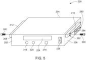
- the perming machine 200 is configured to facilitate perming/curling of hairs, and includes a form, a shape, and a structure similar to the first drawer 110a to enable an arrangement and positioning of the perming machine 200 within the chamber 118 in place of the first drawer 1 10a.
- the perming machine 200 includes a front end 202, a rear end 204, and a pair of sidewalls 206, 208 extending from the front end 202 to the rear end 204.
- the perming machine 200 includes a pair of bars 210, 212 extending outwardly of the pair of sidewalls 206, 208 in the lateral direction and extending from the front end 202 to the rear end 204 in the longitudinal direction.
- the pair of bars 210, 212 are adapted to engage with the pair of guide rails 148a of the housing 104 to enable the positioning and arrangement of the perming machine 200 within the chamber 118 in place of the first drawer 1 10a.
- the perming machine 200 includes a plurality of switches or buttons or knobs, for example, a start switch 216, a temperature selector 218, a timer 220, etc. disposed at the front end 202.
- the start switch 216 enables the user to start or stop the perming machine 200, while a temperature selector 218 enables a control and a selection of a desired temperature for perming hairs.
- the timer 220 enables the user (i.e., a hair dresser) to select a desired time duration for heating the hairs.
- the perming machine 200 is automatically stopped and/or an alarm is actuated to inform the hair dresser about completion of the perming of the hair.
- the perming machine 200 may include a display 224 located at the front end 202 of the perming machine 200.
- the display 224 may be a digital display or an analog display.
- the perming machine 200 includes a power switch 226 to enable or disable a supply of electricity to the perming machine 200 from an external power source.
- the perming machine 200 To enable an electric connection of the perming machine 200 with the external power source, the perming machine 200, as shown in FIG. 6 , includes a power socket 230 located at the rear end 204 of the perming machine, and a power cable 232 adapted to be removably engaged to the power socket 230 and the external power source. Moreover, the perming machine 200 includes one or more connectors 234, for example, USB connectors or ports, located at the rear end 204 for connecting one or more perming cables 240 to the perming machine 200. The perming cables 240 are configured to receive perming rods 242 and supply electric power to the perming rods 242.
- the perming cables 240 extends outwardly of the housing 104, i.e., trolley 102 through the at least one opening 140 and extend over the rear handle 154 arranged in the vertical position, as shown in FIG. 4 .
- the flap 144 is pivoted outwardly relative to the housing 104.
- the rear handle 154 includes a holding structure 250, for example, a rubber grip 252, shown in FIGS. 2 to 4 , connected to the central bar 156.
- the rubber grip 252 provides necessary friction to the cables 240 to prevent a falling off of the perming cables 240 from the rear handle 154.
- one or more clips may be used to connect/secure the perming cables 240 with the rear handle 154.
- the perming machine 200 includes a plurality of ventilation holes 280 to enable ventilation inside the perming machine to remove heat from the perming machine 200.
- the perming machine 200 includes a retention structure 282 to secure the perming machine 200 with the housing 104.
- the retention structure 282 includes a plurality of grooves, for example, a first groove 284, arranged on the first bar 210, and a second groove 286 arranged on the second bar 212.
- the retention structure 282 along with the mounting structure 196 of the trolley 102 facilitates securing/coupling of the perming machine 200 with the housing 104, i.e., trolley 102.
- screws 300 are inserted through the aligned grooves 284, 286 of the perming machine 200 and the holes 198, 199 of the housing 104.
- a first screw 300 extends through the first hole 198 of the housing 104 and extends inside the first groove 284 of the perming machine 200.
- the first groove 284 may be a threaded groove to enable threaded engagement of the first screw 300 with the perming machine 200.
- a second screw 300 extends through the second hole 199 of the housing 104 and extends inside the second groove 286 of the perming machine 200.
- the second groove 286 may be a threaded groove to enable threaded engagement of the second screw 300 with the perming machine 200.
- one of the retention structure 282 and the mounting structure 196 includes at least one protrusion, for example, tab, and other of the retention structure 282 and the mounting structure 196 includes at least one groove or hole to receive the protrusion to secure the perming machine 200 to the housing 104.
Landscapes
- Handcart (AREA)
Priority Applications (1)
| Application Number | Priority Date | Filing Date | Title |
|---|---|---|---|
| EP23158395.6A EP4420557A1 (de) | 2023-02-24 | 2023-02-24 | Modularer wagen zur lagerung von stallartikeln |
Applications Claiming Priority (1)
| Application Number | Priority Date | Filing Date | Title |
|---|---|---|---|
| EP23158395.6A EP4420557A1 (de) | 2023-02-24 | 2023-02-24 | Modularer wagen zur lagerung von stallartikeln |
Publications (1)
| Publication Number | Publication Date |
|---|---|
| EP4420557A1 true EP4420557A1 (de) | 2024-08-28 |
Family
ID=85382610
Family Applications (1)
| Application Number | Title | Priority Date | Filing Date |
|---|---|---|---|
| EP23158395.6A Pending EP4420557A1 (de) | 2023-02-24 | 2023-02-24 | Modularer wagen zur lagerung von stallartikeln |
Country Status (1)
| Country | Link |
|---|---|
| EP (1) | EP4420557A1 (de) |
Citations (4)
| Publication number | Priority date | Publication date | Assignee | Title |
|---|---|---|---|---|
| KR200320615Y1 (ko) * | 2003-04-24 | 2003-07-23 | 박강수 | 가열된 유체를 열원으로 하는 세팅기 |
| US7213817B2 (en) * | 2004-11-09 | 2007-05-08 | Maggie Cheung | Foldable trolley |
| KR20190111187A (ko) * | 2018-03-22 | 2019-10-02 | 주식회사 디케이코리아 | 식료품 운반 카트 |
| KR102246851B1 (ko) * | 2019-12-03 | 2021-04-29 | 전동근 | 이미용 트레이 |
-
2023
- 2023-02-24 EP EP23158395.6A patent/EP4420557A1/de active Pending
Patent Citations (4)
| Publication number | Priority date | Publication date | Assignee | Title |
|---|---|---|---|---|
| KR200320615Y1 (ko) * | 2003-04-24 | 2003-07-23 | 박강수 | 가열된 유체를 열원으로 하는 세팅기 |
| US7213817B2 (en) * | 2004-11-09 | 2007-05-08 | Maggie Cheung | Foldable trolley |
| KR20190111187A (ko) * | 2018-03-22 | 2019-10-02 | 주식회사 디케이코리아 | 식료품 운반 카트 |
| KR102246851B1 (ko) * | 2019-12-03 | 2021-04-29 | 전동근 | 이미용 트레이 |
Similar Documents
| Publication | Publication Date | Title |
|---|---|---|
| US6591952B1 (en) | Cosmetic appliance storage and cord management apparatus | |
| US7513361B1 (en) | Powered grooming unit | |
| US4446972A (en) | Storage device for a portable hair dryer or the like | |
| AU2004202859B2 (en) | Interlocking charging stands | |
| US6702608B2 (en) | Electric workstation with power reel cords | |
| US9675172B2 (en) | Medicine cabinet | |
| US4718741A (en) | Electrified table and support structure | |
| US5875794A (en) | Hair care product organizing and storage system | |
| US20160286967A1 (en) | Foot Care and Grooming Apparatus that can be Placed Underneath a Mattress or Cushion | |
| US20100017998A1 (en) | Multi-use mobile vacuum cart | |
| JP2013520326A (ja) | 動力工具収納および包装システム | |
| US12059067B2 (en) | Portable caddy organizer | |
| US20130175415A1 (en) | Hair Appliance Valet | |
| KR101805869B1 (ko) | 다양한 수납기능을 갖는 이미용 다용도 작업대 | |
| US3287076A (en) | Electric toothbrush storage case | |
| US20120205497A1 (en) | Method and apparatus for storing and recharging electronic devices | |
| CN113412072A (zh) | 用于展示和包装美发工具的装置 | |
| KR101844946B1 (ko) | 가정용 간이 이·미용 트레이 | |
| US4683607A (en) | Vacuum cleaner accessory bracket | |
| US20070278206A1 (en) | Curling Iron Utility Case | |
| US20070125681A1 (en) | Decorative multi-compartment storage system and furnishing | |
| KR101943970B1 (ko) | 이동식 이미용 작업대 | |
| KR20180032140A (ko) | 전열 미용기구 보관이 가능한 이동식 미용작업대 | |
| KR200262408Y1 (ko) | 이동식 미용 작업대 | |
| KR20090022867A (ko) | 화장용구 및 화장품 보관 케이스 |
Legal Events
| Date | Code | Title | Description |
|---|---|---|---|
| PUAI | Public reference made under article 153(3) epc to a published international application that has entered the european phase |
Free format text: ORIGINAL CODE: 0009012 |
|
| STAA | Information on the status of an ep patent application or granted ep patent |
Free format text: STATUS: THE APPLICATION HAS BEEN PUBLISHED |
|
| AK | Designated contracting states |
Kind code of ref document: A1 Designated state(s): AL AT BE BG CH CY CZ DE DK EE ES FI FR GB GR HR HU IE IS IT LI LT LU LV MC ME MK MT NL NO PL PT RO RS SE SI SK SM TR |
|
| STAA | Information on the status of an ep patent application or granted ep patent |
Free format text: STATUS: REQUEST FOR EXAMINATION WAS MADE |
|
| 17P | Request for examination filed |
Effective date: 20250102 |
|
| STAA | Information on the status of an ep patent application or granted ep patent |
Free format text: STATUS: EXAMINATION IS IN PROGRESS |
|
| 17Q | First examination report despatched |
Effective date: 20251211 |