EP4420559A1 - Systemmöbel mit regalen mit beleuchtung - Google Patents
Systemmöbel mit regalen mit beleuchtung Download PDFInfo
- Publication number
- EP4420559A1 EP4420559A1 EP22883944.5A EP22883944A EP4420559A1 EP 4420559 A1 EP4420559 A1 EP 4420559A1 EP 22883944 A EP22883944 A EP 22883944A EP 4420559 A1 EP4420559 A1 EP 4420559A1
- Authority
- EP
- European Patent Office
- Prior art keywords
- electrode
- coupled
- connection
- shelf
- pillar portion
- Prior art date
- Legal status (The legal status is an assumption and is not a legal conclusion. Google has not performed a legal analysis and makes no representation as to the accuracy of the status listed.)
- Granted
Links
Images




Classifications
-
- A—HUMAN NECESSITIES
- A47—FURNITURE; DOMESTIC ARTICLES OR APPLIANCES; COFFEE MILLS; SPICE MILLS; SUCTION CLEANERS IN GENERAL
- A47B—TABLES; DESKS; OFFICE FURNITURE; CABINETS; DRAWERS; GENERAL DETAILS OF FURNITURE
- A47B57/00—Cabinets, racks or shelf units, characterised by features for adjusting shelves or partitions
- A47B57/06—Cabinets, racks or shelf units, characterised by features for adjusting shelves or partitions with means for adjusting the height of the shelves
- A47B57/08—Cabinets, racks or shelf units, characterised by features for adjusting shelves or partitions with means for adjusting the height of the shelves consisting of grooved or notched ledges, uprights or side walls
- A47B57/10—Cabinets, racks or shelf units, characterised by features for adjusting shelves or partitions with means for adjusting the height of the shelves consisting of grooved or notched ledges, uprights or side walls the grooved or notched parts being the side walls or uprights themselves
-
- A—HUMAN NECESSITIES
- A47—FURNITURE; DOMESTIC ARTICLES OR APPLIANCES; COFFEE MILLS; SPICE MILLS; SUCTION CLEANERS IN GENERAL
- A47B—TABLES; DESKS; OFFICE FURNITURE; CABINETS; DRAWERS; GENERAL DETAILS OF FURNITURE
- A47B96/00—Details of cabinets, racks or shelf units not covered by a single one of groups A47B43/00 - A47B95/00; General details of furniture
- A47B96/06—Brackets or similar supporting means for cabinets, racks or shelves
- A47B96/061—Cantilever brackets
-
- A—HUMAN NECESSITIES
- A47—FURNITURE; DOMESTIC ARTICLES OR APPLIANCES; COFFEE MILLS; SPICE MILLS; SUCTION CLEANERS IN GENERAL
- A47B—TABLES; DESKS; OFFICE FURNITURE; CABINETS; DRAWERS; GENERAL DETAILS OF FURNITURE
- A47B96/00—Details of cabinets, racks or shelf units not covered by a single one of groups A47B43/00 - A47B95/00; General details of furniture
- A47B96/14—Bars, uprights, struts, or like supports, for cabinets, brackets, or the like
- A47B96/1408—Bars, uprights, struts, or like supports, for cabinets, brackets, or the like regularly perforated
-
- A—HUMAN NECESSITIES
- A47—FURNITURE; DOMESTIC ARTICLES OR APPLIANCES; COFFEE MILLS; SPICE MILLS; SUCTION CLEANERS IN GENERAL
- A47F—SPECIAL FURNITURE, FITTINGS, OR ACCESSORIES FOR SHOPS, STOREHOUSES, BARS, RESTAURANTS OR THE LIKE; PAYING COUNTERS
- A47F11/00—Arrangements in shop windows, shop floors or show cases
- A47F11/06—Means for bringing about special optical effects
- A47F11/10—Arrangements of light sources
-
- A—HUMAN NECESSITIES
- A47—FURNITURE; DOMESTIC ARTICLES OR APPLIANCES; COFFEE MILLS; SPICE MILLS; SUCTION CLEANERS IN GENERAL
- A47F—SPECIAL FURNITURE, FITTINGS, OR ACCESSORIES FOR SHOPS, STOREHOUSES, BARS, RESTAURANTS OR THE LIKE; PAYING COUNTERS
- A47F5/00—Show stands, hangers, or shelves characterised by their constructional features
- A47F5/0043—Show shelves
-
- A—HUMAN NECESSITIES
- A47—FURNITURE; DOMESTIC ARTICLES OR APPLIANCES; COFFEE MILLS; SPICE MILLS; SUCTION CLEANERS IN GENERAL
- A47B—TABLES; DESKS; OFFICE FURNITURE; CABINETS; DRAWERS; GENERAL DETAILS OF FURNITURE
- A47B2220/00—General furniture construction, e.g. fittings
- A47B2220/0075—Lighting
- A47B2220/0077—Lighting for furniture, e.g. cupboards and racks
-
- A—HUMAN NECESSITIES
- A47—FURNITURE; DOMESTIC ARTICLES OR APPLIANCES; COFFEE MILLS; SPICE MILLS; SUCTION CLEANERS IN GENERAL
- A47B—TABLES; DESKS; OFFICE FURNITURE; CABINETS; DRAWERS; GENERAL DETAILS OF FURNITURE
- A47B91/00—Feet for furniture in general
- A47B91/02—Adjustable feet
-
- F—MECHANICAL ENGINEERING; LIGHTING; HEATING; WEAPONS; BLASTING
- F21—LIGHTING
- F21V—FUNCTIONAL FEATURES OR DETAILS OF LIGHTING DEVICES OR SYSTEMS THEREOF; STRUCTURAL COMBINATIONS OF LIGHTING DEVICES WITH OTHER ARTICLES, NOT OTHERWISE PROVIDED FOR
- F21V33/00—Structural combinations of lighting devices with other articles, not otherwise provided for
- F21V33/0004—Personal or domestic articles
- F21V33/0012—Furniture
-
- F—MECHANICAL ENGINEERING; LIGHTING; HEATING; WEAPONS; BLASTING
- F21—LIGHTING
- F21W—INDEXING SCHEME ASSOCIATED WITH SUBCLASSES F21K, F21L, F21S and F21V, RELATING TO USES OR APPLICATIONS OF LIGHTING DEVICES OR SYSTEMS
- F21W2131/00—Use or application of lighting devices or systems not provided for in codes F21W2102/00-F21W2121/00
- F21W2131/30—Lighting for domestic or personal use
- F21W2131/301—Lighting for domestic or personal use for furniture
Definitions
- the present disclosure relates to system furniture including a shelf provided with a lighting, and more specifically, to system furniture capable of adjusting the height of a shelf provided with a lighting while allowing electrical connection, and capable of easily assembling and disassembling the shelf provided with the lighting.
- lighting devices are installed on furniture such as beds, desks, display cases, and dressers for interior effects or to illuminate specific spaces.
- Aesthetic effects may be obtained through lighting devices installed on furniture, and functional effects may be obtained because the lighting devices illuminate specific spaces.
- Lighting devices having a diffusion plate may be installed in an interior cabinet such as a display case with shelves or a built-in closet. By installing lighting devices in the interior cabinet, the interior decoration effect of the interior cabinet may be improved and specific points of the interior cabinet may be illuminated.
- the lighting devices installed in the interior cabinet may be installed on a shelf provided in the interior cabinet. However, installing lighting devices on a shelf may cause following issues.
- a point of the shelf on which the lighting device is installed has to be electrically connected to outside.
- a point on the shelf where the lighting device is installed may be electrically connected to the outside through an electric wire.
- a built-in closet denotes an interior cabinet fixed to a wall.
- the built-in closet may be installed while fixing pillars or back plates thereof to the wall.
- the pillars or back plates of the built-in closet are fixedly installed on the wall, it is difficult to re-construct the built-in closet.
- the pillars or back plates of the built-in closet are directly fixed to the wall, there may be a damage to the built-in closet during installing and disassembling the built-in closet.
- the present disclosure provides system furniture having a shelf provided with a lighting, which is capable of adjusting a height of a shelf provided with a lighting while allowing electrical connection and easily installed and disassembled.
- system furniture including a shelf, the system furniture including: a bottom plate formed in a plate shape; a connection bracket coupled to the bottom plate; a first electrode provided on the connection bracket and connected to an electrical connection line extending to outside; a pillar portion coupled to the connection bracket; a second electrode extending in a height direction of the pillar portion and coming into contact with the first electrode when the pillar portion is coupled to the connection bracket; a shelf coupled to the pillar portion; a third electrode provided on the shelf and coming into contact with the second electrode when the shelf is coupled to the pillar portion; and a lighting provided on the shelf and connected to the third electrode.
- the system furniture having the shelf with the lighting according to the present disclosure may further include a horizontal adjustment frame coupled to a lower portion of the bottom plate and adjusting a height between the bottom plate and ground.
- the first electrode may include a first electrode connection portion that is bent outward while protruding to an upper portion of the connection bracket
- the second electrode may include a thin film that is provided inside the pillar portion and extends in a height direction of the pillar portion, and when the pillar portion is coupled to the connection bracket, the first electrode connection portion and the second electrode may come into contact with each other and are electrically connected to each other.
- the first electrode connection portion may include an elastic member, and the first electrode connection portion may be elastically pressed to be spread outward when the pillar portion is coupled to the connection bracket.
- the pillar portion may be provided with a wing portion protruding to an outer side of the pillar portion, and a block formed in a hexahedron shape may be coupled to the wing portion.
- the system furniture having the shelf provided with the lighting according to the present disclosure may further include a back plate provided between two pillar portions, wherein the back plate may be coupled to the block.
- the shelf may include a connection portion provided with the third electrode and coupled to the pillar portion, and a support portion provided between two connection portions.
- the pillar portion may include a rail provided with a plurality of coupling holes in a height direction of the pillar portion, a plurality of hook portions formed in hook shapes may be provided on one side of the connection portion, and the connection portion may be coupled to the pillar portion when the plurality of hook portions are inserted into the plurality of coupling holes.
- the third electrode provided in the connection portion may include a third electrode connection portion that is bent and protrudes to an outer side of the hook portion
- the second electrode may include a thin film that is provided inside the pillar portion and extends in a height direction of the pillar portion, and when the hook portions are inserted into the coupling holes, the third electrode connection portion may come into contact with the second electrode and may be electrically connected to the second electrode.
- the third electrode connection portion may include an elastic member, and when the hook portions are inserted into the coupling holes, the third electrode connection portion may be elastically pressed to be spread outward.
- the system furniture having the shelf provided with the lighting according to the present disclosure may include a connection pin that is provided in the connection portion, is connected to the third electrode via an electric wire, and is connected to the lighting via an electric wire.
- the support portion may include a support plate formed in a plate shape and a frame coupled to an outer side of the support plate, the frame may have an internal space formed therein, and the electric wire connecting the connection pin to the lighting may extend in the internal space of the frame.
- the present disclosure relates to system furniture including a shelf provided with a lighting, in which connection portions of a shelf are selectively coupled to a plurality of couplig holes provide in a rail of a pillar portion so that a second electrode provided in the pillar portion comes into contact with a third electrode provided in the shelf, and accordingly, the height of the shelf may be adjusted while allowing electrical connection.
- the system furniture is fixed to a wall via blocks coupled to a pillar portion while fixing a back plate thereof via the blocks coupled to the pillar portion, and thus, there are advantages of easy installation and disassembly.
- a bottom plate, the pillar portion, and the shelf are electrically separated from one another, and a first electrode provided in the bottom plate, the second electrode provided in the pillar portion, and the third electrode provided in the shelf come into contact with one another to be electrically conducted, and accordingly, an electrical short-circuit point may be easily found.
- the expression “include” or “may include” refers to existence of a corresponding function, operation, or element, and does not limit one or more additional functions, operations, or elements.
- the terms such as “including,” “having,” and “comprising” are intended to indicate the existence of the features, numbers, steps, actions, components, parts, or combinations thereof disclosed in the specification, and are not intended to preclude the possibility that one or more other features, numbers, steps, actions, components, parts, or combinations thereof may exist or may be added.
- the present disclosure relates to system furniture including a shelf provided with a lighting, and to system furniture including a shelf provided with a lighting, which is capable of adjusting a height of the shelf provided with the lighting while allowing electrical connection and is easily installed and disassembled.
- System furniture including a shelf provided with a lighting may include a built-in closet or a display case.
- the disclosure is not limited thereto, and the system furniture including the shelf provided with the lighting may include various kinds of furniture provided that the furniture includes the shelf provided with the lighting.
- System furniture including a shelf provided with a lighting may include a bottom plate 110, a connection bracket 120, a first electrode 130, a pillar portion 140, a second electrode 150, a shelf 160, a third electrode 170, and a lighting 180.
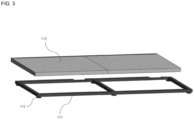
- the bottom plate 110 is formed in a plate shape and may be a lower plate of the system furniture. A plurality of bottom plates 110 may be provided, and the bottom plate 110 may be installed on the ground.
- the system furniture including the shelf provided with the lighting may further include a horizontal adjustment frame 111.
- the horizontal adjustment frame 111 is coupled to a lower portion of the bottom plate 110 and may adjust a height between the bottom plate 110 and the ground.
- the bottom plate 110 When installing the bottom plate 110 on the ground, the bottom plate 110 may not be horizontal due to the inclination of the ground.
- the horizontal adjustment frame 111 is coupled to the lower portion of the bottom plate 110 to install the bottom plate 110 horizontally.
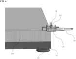
- the horizontal adjustment frame 111 may include a plurality of adjustment screws 112 and may adjust the height of the bottom plate 110 by tightening or loosening the plurality of adjustment screws 112.
- the horizontal adjustment frame 111 is not limited to the adjustment of the height of the bottom plate 110 via the adjustment screws 112, and the horizontal adjustment frame 111 may adjust the height of the bottom plate 110 via another structure. Also, the horizontal adjustment frame 111 may be formed integrally with the bottom plate 110.
- connection bracket 120 is coupled to the bottom plate 110.
- the connection bracket 120 may be a bracket for coupling the pillar portion 140 perpendicularly to the bottom plate 110.
- connection bracket 120 As the connection bracket 120 is coupled to the bottom plate 110 and the pillar portion 140 is coupled to the connection bracket 120, the pillar portion 140 may be installed perpendicularly to the bottom plate 110.
- the connection bracket 120 may be manufactured separately from the bottom plate 110 and may be manufactured integrally with the bottom plate 110.
- the first electrode 130 is provided on the connection bracket 120 and is connected to an electrical connection line 121 extending to the outside.
- the electrical connection line 121 may be connected to external electricity and includes an electric wire extending to the outside.
- the first electrode 130 is electrically connected to the electrical connection line 121 and is provided on the connection bracket 120.
- the first electrode 130 may include a pair of electrodes including a negative electrode and a positive electrode. A pair of electrodes may be electrically connected to a pair of electrical connection lines 121.
- the pillar portion 140 is coupled to the connection bracket 120.
- the pillar portion 140 may be formed in a bar shape extending in a height direction and may be a pillar that supports a back plate 191 of the system furniture.
- the pillar portion 140 may be coupled to the connection bracket 120 while being inserted into the inner space of the connection bracket 120 and may be coupled perpendicularly to the connection bracket 120. As the connection bracket 120 is coupled to the bottom plate 110 and the pillar portion 140 is coupled to the connection bracket 120, the pillar portion 140 may be installed perpendicularly to the bottom plate 110.
- the second electrode 150 extends in the height direction of the pillar portion 140.
- the second electrode 150 may include a pair of electrodes including a negative electrode and a positive electrode.
- the second electrode 150 may come into contact with the first electrode 130 when the pillar portion 140 is coupled to the connection bracket 120.
- the negative electrode of the second electrode 150 may come into contact with the negative electrode of the first electrode 130 and the positive electrode of the second electrode 150 may come into contact with the positive electrode of the first electrode 130.
- the first electrode 130 and the second electrode 150 may be electrically connected to each other.
- the first electrode 130 includes a first electrode connection portion 131 that protrudes to the upper portion of the connection bracket 120 and is bent outward.
- the second electrode 150 according to the embodiment of the present disclosure may include a thin film that is provided inside the pillar portion 140 and extends in the height direction of the pillar portion 140.
- the first electrode connection portion 131 comes into contact with the second electrode 150 including the thin film and then the first electrode 130 and the second electrode 150 may be electrically connected to each other.
- the first electrode connection portion 131 may include a negative electrode and a positive electrode.
- the negative electrode of the second electrode 150 may come into contact with the negative electrode of the first electrode connection portion 131 and the positive electrode of the second electrode 150 may come into contact with the positive electrode of the first electrode connection portion 131.
- the first electrode 130 and the second electrode 150 come into contact with each other and are electrically connected to each other only with the process of coupling or assembling the pillar portion 140 with the connection bracket 120.
- the first electrode connection portion 131 may include an elastic member, and before the pillar portion 140 is coupled to the connection bracket 120, the first electrode connection portion 131 may be in a state of being spread outward.
- the first electrode connection portion 131 that is spread outward may be gathered inward by the pillar portion 140. That is, the pillar portion 140 may be press-fitted into the connection bracket 120 while gathering inward the first electrode connection portion 131 having been spread outward.
- the first electrode connection portion 131 When the first electrode connection portion 131 is gathered inward by the pillar portion 140, an elastic restoring force is generated from the first electrode connection portion 131 including the elastic member. When the pillar portion 140 is coupled to the connection bracket 120, the first electrode connection portion 131 may be elastically pressed to be spread outward due to the elastic restoring force.
- the first electrode connection portion 131 when the pillar portion 140 is coupled to the connection bracket 120, the first electrode connection portion 131 is elastically pressed to be spread outward, and accordingly, the first electrode connection portion 131 may be in a firm contact with the second electrode 150.
- the shelf 160 is coupled to the pillar portion 140.
- the shelf 160 includes a support plate 165 formed in a plate shape.
- the third electrode 170 is provided on the shelf 160, and when the shelf 160 is coupled to the pillar portion 140, the third electrode 170 comes into contact with the second electrode 150.
- the third electrode 170 may include a pair of electrodes including a negative electrode and a positive electrode.
- the negative electrode of the third electrode 170 may come into contact with the negative electrode of the second electrode 150 and the positive electrode of the third electrode 170 may come into contact with the positive electrode of the second electrode 150.
- the second electrode 150 and the third electrode 170 may be electrically connected to each other.
- the second electrode 150 includes a thin film and extends along the height direction of the pillar portion 140. Therefore, even when the shelf 160 is coupled to any point in the height of the pillar portion 140, the second electrode 150 and the third electrode 170 may come into contact with each other to be electrically connected to each other.
- the shelf 160 includes a connection portion 161 provided with the third electrode 170 and coupled to the pillar portion 140, and a support portion 164 provided between two connection portions 161.
- the pillar portion 140 includes a rail 141 provided with a plurality of coupling holes 142 along the height direction of the pillar portion 140.
- the coupling hole 142 is a hole to which a hook portion 162, which is described later, is coupled, and may pass through the rail 141.
- the rail 141 may be provided with the plurality of coupling holes 142 in the height direction of the pillar portion 140.
- the rail 141 may be a member that is fitted and coupled to the pillar portion 140, but is not limited thereto.
- the rail 141 may be manufactured integrally with the pillar portion 140.
- connection portion 161 of the shelf 160 may be formed as a cantilever, and a plurality of hook portions 162 that are formed in hook shapes may be provided on one side of the connection portion 161.
- connection portion 161 may be coupled to the pillar portion 140 as the hook portions 162 formed in the hook shapes are inserted into the coupling holes 142.
- the hook portion 162 may be coupled to one or more of the plurality of coupling holes 142.
- the height at which the connection portion 161 is coupled to the pillar portion 140 may be adjusted by changing the coupling holes 142 to which the hook portions 162 are coupled. As such, the height of the pillar portion 140, to which the shelf 160 is coupled, may be adjusted.
- the third electrode 170 may be provided on the connection portion 161, in particular, in the hook portion 162 of the connection portion 161.
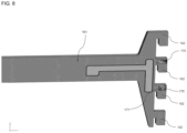
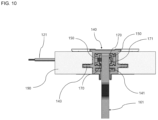
- the third electrode 170 may include a third electrode connection portion 171 that is bent to protrude to the outside of the hook portion 162. Referring to FIG. 8 , the third electrode connection portion 171 may be bent and protrude to the outside of the hook portion 162.
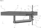
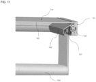
- the second electrode 150 may include the thin film that is provided inside the pillar portion 140 and extends in the height direction of the pillar portion 140. Referring to FIG. 9 and 10 , when the hook portion 162 is inserted into the coupling hole 142 of the rail 141, the third electrode connection portion 171 protruding from the hook portion 162 comes into contact with the second electrode 150 so that the third electrode 170 and the second electrode 150 may be electrically connected to each other.
- the third electrode connection portion 171 may include a negative electrode and a positive electrode.
- the negative electrode of the second electrode 150 may come into contact with the negative electrode of the third electrode connection portion 171 and the positive electrode of the second electrode 150 may come into contact with the positive electrode of the third electrode connection portion 171.
- the second electrode 150 and the third electrode 170 may be electrically connected to each other only through a process of coupling or assembling the hook portions 162 of the shelf 160 with the pillar portion 140.
- the second electrode 150 includes the thin film extending in the height direction of the pillar portion 140, and thus, the third electrode 170 and the second electrode 150 may come into contact with each other to be electrically connected to each other without regard to the height of the pillar portion 140, to which the hook portion 162 is coupled.
- the second electrode 150 and the third electrode 170 may come into contact with each other and may be electrically connected to each other. As such, even when the height of installing the shelf 160 onto the pillar portion 140 is adjusted, the second electrode 150 and the third electrode 170 come into contact with each other and may be electrically connected to each other.
- the third electrode connection portion 171 may include an elastic member, and before the hook portion 162 is inserted into the coupling hole 142, the third electrode connection portion 171 may be in a state of being protruding outward.
- the third electrode connection portion 171 having been spread outward may be gathered inward by the pillar portion 140. That is, the hook portion 162 may be press-fitted into the pillar portion 140 via the coupling hole 142 while gathering the third electrode connection portion 171 inward, the third electrode connection portion 171 being in a spread state outwardly.
- the third electrode connection portion 171 When the third electrode connection portion 171 is gathered inward by the pillar portion 140, an elastic restoring force is generated from the third electrode connection portion 171 including the elastic member. When the hook portion 162 is inserted into the coupling hole 142, the third electrode connection portion 171 may be elastically pressed to spread outward due to the elastic restoring force.
- the third electrode connection portion 171 is elastically pressed to be spread outward, and accordingly, the third electrode connection portion 171 may firmly come into contact with the second electrode 150.
- the lighting 180 is provided on the shelf 160 and connected to the third electrode 170.
- the lighting 180 may be provided at various points on the shelf 160 and may be provided in the form of a diffusion plate. However, the lighting is not limited to the above example, and the lighting 180 may be provided on the shelf 160 in various forms.
- connection pin 163 may be provided in the connection portion 161.
- the connection pin 163 is connected to the third electrode 170 through an electric wire 169 and may be connected to the lighting 180 through a wire.
- the first electrode 130 provided on the connection bracket 120 receives electricity through the electrical connection line 121, and the electricity supplied to the first electrode 130 is transferred to the second electrode 150.
- the electricity transferred to the second electrode 150 is transferred to the third electrode 170, and the electricity transferred to the third electrode 170 is transferred to the connection pin 163.
- the electricity transferred to the connection pin 163 is transferred to the lighting 180 through the electric wire, and as such, the lighting 180 may emit light.
- the support portion 164 includes a support plate 165 formed in a plate shape and a frame 166 coupled to the outside of the support plate 165.
- the support plate 165 may be a plate-shaped member, and the frame 166 may support the support plate 165.
- connection portion 161 may be coupled to the frame 166 through a fixing bracket 168, screws, pins, etc., and an internal space 167 may be formed in the frame 166.
- the electric wire connecting the connection pin 163 to the lighting 180 may extend in the internal space 167 of the frame 166.
- the electric wire extending from the connection pin 163 provided in the connection portion 161 to the lighting 180 may extend while passing through the internal space 167 of the frame 166. As such, the electric wire connecting the connection pin 163 to the lighting 180 may not be exposed to the outside.
- connection pin 163 may be provided with a controller that may control whether to supply electricity to the lighting 180.
- the controller may be configured to supply or block the electricity from the connection pin 163 to the lighting 180 according to an external signal.
- the external signal may be generated via a switch and may be a wireless signal generated from the outside.
- the controller may be provided, but is not limited to, in the connection pin 163, and the controller may be provided at various positions provided that the electricity may be fed to the lighting 180 or blocked.
- the pillar portion 140 may be provided with a wing portion 143 protruding to the outside of the pillar portion 140.
- a block 190 formed in a hexahedron shape may be coupled to the wing portion 143.
- the wing portion 143 may be a protrusion protruding outward from the pillar portion 140, and the block 190 may be fixedly coupled to the wing portion 143.
- the system furniture including the shelf provided with the lighting according to the embodiment of the present disclosure may further include a back plate 191 provided between two pillar portions 140.
- the back plate 191 may be formed in a plate shape and may be installed between two pillar portions 140.
- the back plate 191 may be installed via the block 190.
- a contact portion between the back plate 191 and the block 190 is fixed via a pin, a tacker, etc. and accordingly, the back plate 191 may be coupled to the block 190. Because the back plate 191 is fixedly coupled via the block 190, the back plate 191 may be easily installed between the two pillar portions 140.
- the system furniture according to the embodiment of the present disclosure may be a built-in closet.
- the system furniture according to the embodiment of the present disclosure is a built-in closet, the system furniture may be installed on the wall through the block 190.
- the bottom plate 110 and the pillar portion 140 are coupled to each other via the connection bracket 120, and the block 190 is fixed to the wall.
- the back plate 191 is coupled to the block 190 via a pin, a tacker, etc. and thus, the system furniture may be installed on the wall.
- the system furniture according to the embodiment of the disclosure is fixed to the wall via the block 190, and accordingly, there is an advantage of easily installing the system furniture provided as the built-in closet on the wall. Also, when the system furniture according to the embodiment of the disclosure is disassembled, the system furniture may be easily separated from the wall by removing the block 190 from the wall.
- the system furniture according to the embodiment of the present disclosure has advantages of easily installation, disassembly, and reconstruction of the system furniture provided as the built-in closet by installing and disassembling the system furniture via the block 190.
- system furniture according to the embodiment of the disclosure has an advantage of preventing damage to the system furniture during installing, disassembling, and reconstructing the system furniture, because the system furniture is fixed to the wall via the block 190 without directly fixing the pillar or back plate to the wall.
- the system furniture according to the embodiment of the disclosure may further include a finishing material 192.
- the finishing material 192 may cover one side surface of the pillar portion 140 after the bottom plate 110, the pillar portion 140, and the shelf 160 are assembled. When one side surface of the pillar portion 140 is covered by the finishing material 192, there is an advantage of obtaining good appearance.
- electric wires are used to supply electricity to the shelf provided with the lighting.
- it is difficult to adjust the height of the shelf due to the wire.
- it may be difficult to find an electrical short-circuit point.
- the system furniture including the shelf provided with the lighting does not use the electric wire, but the first electrode and the second electrode may be electrically connected to each other through the process of installing, coupling, and assembling the pillar portion with the connection bracket, and the second electrode and the third electrode may be connected to each other via the process of installing, coupling, and assembling the connection portion of the shelf with the pillar portion.
- connection portion of the shelf is selectively coupled to a plurality of coupling holes provided in the rail of the pillar portion so that the second electrode provided in the pillar portion comes into contact with the third electrode provided in the shelf, and accordingly, the height of the shelf may be adjusted while allowing the electric connection.
- the bottom plate, the pillar portion, and the shelf are electrically separated, and then, the first electrode provided in the connection bracket of the bottom plate, the second electrode provided in the pillar portion, and the third electrode provided in the connection portion of the shelf come into contact with one another to be electrically conducted, and accordingly, the electrical short-circuit point may be easily found.
- the system furniture including the shelf provided with the lighting according to the embodiment of the present disclosure, is assembled by coupling the pillar portion to the bottom plate provided with the connection bracket and the connection portion of the shelf to the rail of the pillar portion, and accordingly, the system furniture may be easily installed and disassembled.
- system furniture including the shelf provided with the lighting has the advantage of easy installation and disassembly because the back plate is fixed via the block coupled to the pillar portion and the system furniture is fixed to the wall via the block coupled to the pillar portion.
Landscapes
- Arrangement Of Elements, Cooling, Sealing, Or The Like Of Lighting Devices (AREA)
Applications Claiming Priority (2)
| Application Number | Priority Date | Filing Date | Title |
|---|---|---|---|
| KR1020210138956A KR102503425B1 (ko) | 2021-10-19 | 2021-10-19 | 조명이 구비된 선반을 포함하는 시스템 가구 |
| PCT/KR2022/015807 WO2023068721A1 (ko) | 2021-10-19 | 2022-10-18 | 조명이 구비된 선반을 포함하는 시스템 가구 |
Publications (3)
| Publication Number | Publication Date |
|---|---|
| EP4420559A1 true EP4420559A1 (de) | 2024-08-28 |
| EP4420559A4 EP4420559A4 (de) | 2025-01-22 |
| EP4420559B1 EP4420559B1 (de) | 2026-04-01 |
Family
ID=85330343
Family Applications (1)
| Application Number | Title | Priority Date | Filing Date |
|---|---|---|---|
| EP22883944.5A Active EP4420559B1 (de) | 2021-10-19 | 2022-10-18 | Systemmöbel mit regalen mit beleuchtung |
Country Status (4)
| Country | Link |
|---|---|
| EP (1) | EP4420559B1 (de) |
| KR (1) | KR102503425B1 (de) |
| CN (1) | CN118139563A (de) |
| WO (1) | WO2023068721A1 (de) |
Families Citing this family (2)
| Publication number | Priority date | Publication date | Assignee | Title |
|---|---|---|---|---|
| KR102662424B1 (ko) * | 2022-06-29 | 2024-05-07 | 주식회사 일광산업 | 플러그식 전원공급 기능을 갖는 조명 찬넬선반 |
| KR102796962B1 (ko) * | 2023-09-22 | 2025-04-17 | 주식회사 일광산업 | 슬라이드식 착탈구조를 갖는 조명 선반 |
Family Cites Families (11)
| Publication number | Priority date | Publication date | Assignee | Title |
|---|---|---|---|---|
| JPH0370418A (ja) * | 1989-08-08 | 1991-03-26 | Nitsupo Denki Kk | 放電灯付組立棚 |
| JP2004344507A (ja) * | 2003-05-23 | 2004-12-09 | Yasuo Maki | 棚柱と棚受け金物に12vを主とする低い電圧の電気を直接流して活用 |
| US20060209537A1 (en) * | 2005-03-17 | 2006-09-21 | Stylmark, Inc. | Display assembly with low voltage powered lighting |
| KR20070106298A (ko) * | 2006-04-28 | 2007-11-01 | 양경호 | 진열장 조명용 엘이디 조명장치 |
| KR100782385B1 (ko) * | 2006-05-17 | 2007-12-07 | 양경호 | 엘이디 조명기구 진열장 |
| KR101052472B1 (ko) * | 2010-09-08 | 2011-07-29 | 고재영 | 선반 조명부재가 내설된 선반 거치대 |
| US9016214B2 (en) * | 2011-11-17 | 2015-04-28 | Altria Group Distribution Company | Shelving system having a shelf with biasing elements to resist inadvertent or accidental detachment from a support rail |
| DE102012202806B4 (de) * | 2012-02-23 | 2014-06-05 | Mladen Pintur | Vorrichtung zur Präsentation von Ware |
| WO2016051613A1 (ja) * | 2014-10-02 | 2016-04-07 | 株式会社 ワン・バイ・ワン | 支持装置 |
| ES2683646T3 (es) * | 2015-03-31 | 2018-09-27 | Pietro Pisati | Unidad de estantería con estantes iluminados |
| KR102251075B1 (ko) * | 2019-08-22 | 2021-05-12 | 주식회사 동성사 | 수직판재의 수직레벨 조절 구조를 갖는 시스템 가구 |
-
2021
- 2021-10-19 KR KR1020210138956A patent/KR102503425B1/ko active Active
-
2022
- 2022-10-18 EP EP22883944.5A patent/EP4420559B1/de active Active
- 2022-10-18 WO PCT/KR2022/015807 patent/WO2023068721A1/ko not_active Ceased
- 2022-10-18 CN CN202280069935.8A patent/CN118139563A/zh active Pending
Also Published As
| Publication number | Publication date |
|---|---|
| EP4420559B1 (de) | 2026-04-01 |
| KR102503425B1 (ko) | 2023-02-24 |
| CN118139563A (zh) | 2024-06-04 |
| WO2023068721A1 (ko) | 2023-04-27 |
| EP4420559A4 (de) | 2025-01-22 |
Similar Documents
| Publication | Publication Date | Title |
|---|---|---|
| EP4420559A1 (de) | Systemmöbel mit regalen mit beleuchtung | |
| US6685150B2 (en) | Conductive speaker mounting system | |
| US10135044B2 (en) | Multi-functional battery box | |
| CN114175419B (zh) | 装拆式供电搁板支撑结构体 | |
| EP3391782B1 (de) | Elektrische regalversorgung und elektrisches regalversorgungssystem damit | |
| WO2017053529A1 (en) | Plug load receptacle | |
| KR20230159221A (ko) | 전극 브라켓 장치가 구비된 시스템 가구 | |
| CA2530845A1 (en) | Self-supporting electrical outlet box | |
| KR101938605B1 (ko) | 가구 설치용 전원공급 장치 및 이를 포함하는 스마트 가구 | |
| CN220209380U (zh) | 一种盖板可调式插座 | |
| CN200982601Y (zh) | 指示灯固定架 | |
| JP3188367U (ja) | 家具用電源コンセント | |
| CN210643462U (zh) | 一种层板可调节的展示架结构 | |
| CN111725670B (zh) | 一种开关插座 | |
| KR200180130Y1 (ko) | 다용도 책상 | |
| JP4447832B2 (ja) | キャビネットケースおよびキャビネット | |
| CN213065693U (zh) | 多配式灯组件 | |
| CN221329100U (zh) | 一种多功能的耳机支架 | |
| CN218975850U (zh) | 支架 | |
| CN218784003U (zh) | 多功能壁挂控制器 | |
| CN221858456U (zh) | 晾衣机平板灯安装框及晾衣机 | |
| CN223585578U (zh) | 沙发 | |
| WO2009099258A1 (en) | Desk lamp | |
| CN221196912U (zh) | 壁挂支架及智能中控屏 | |
| CN223954073U (zh) | 一种电源安装结构及包括该电源安装结构的灯具 |
Legal Events
| Date | Code | Title | Description |
|---|---|---|---|
| STAA | Information on the status of an ep patent application or granted ep patent |
Free format text: STATUS: THE INTERNATIONAL PUBLICATION HAS BEEN MADE |
|
| PUAI | Public reference made under article 153(3) epc to a published international application that has entered the european phase |
Free format text: ORIGINAL CODE: 0009012 |
|
| STAA | Information on the status of an ep patent application or granted ep patent |
Free format text: STATUS: REQUEST FOR EXAMINATION WAS MADE |
|
| 17P | Request for examination filed |
Effective date: 20240405 |
|
| AK | Designated contracting states |
Kind code of ref document: A1 Designated state(s): AL AT BE BG CH CY CZ DE DK EE ES FI FR GB GR HR HU IE IS IT LI LT LU LV MC ME MK MT NL NO PL PT RO RS SE SI SK SM TR |
|
| A4 | Supplementary search report drawn up and despatched |
Effective date: 20250103 |
|
| DAV | Request for validation of the european patent (deleted) | ||
| DAX | Request for extension of the european patent (deleted) | ||
| RIC1 | Information provided on ipc code assigned before grant |
Ipc: F21V 33/00 20060101ALN20241219BHEP Ipc: A47F 5/00 20060101ALN20241219BHEP Ipc: A47B 91/02 20060101ALN20241219BHEP Ipc: A47B 57/10 20060101ALI20241219BHEP Ipc: A47B 96/14 20060101ALI20241219BHEP Ipc: A47B 96/06 20060101ALI20241219BHEP Ipc: A47B 57/06 20060101AFI20241219BHEP |
|
| GRAJ | Information related to disapproval of communication of intention to grant by the applicant or resumption of examination proceedings by the epo deleted |
Free format text: ORIGINAL CODE: EPIDOSDIGR1 |
|
| GRAP | Despatch of communication of intention to grant a patent |
Free format text: ORIGINAL CODE: EPIDOSNIGR1 |
|
| GRAP | Despatch of communication of intention to grant a patent |
Free format text: ORIGINAL CODE: EPIDOSNIGR1 |
|
| RIC1 | Information provided on ipc code assigned before grant |
Ipc: A47B 57/06 20060101AFI20251007BHEP Ipc: A47B 96/06 20060101ALI20251007BHEP Ipc: A47B 96/14 20060101ALI20251007BHEP Ipc: A47B 57/10 20060101ALI20251007BHEP Ipc: A47B 91/02 20060101ALN20251007BHEP Ipc: A47F 5/00 20060101ALN20251007BHEP Ipc: F21V 33/00 20060101ALN20251007BHEP |
|
| STAA | Information on the status of an ep patent application or granted ep patent |
Free format text: STATUS: GRANT OF PATENT IS INTENDED |
|
| RIC1 | Information provided on ipc code assigned before grant |
Ipc: A47B 57/06 20060101AFI20251028BHEP Ipc: A47B 96/06 20060101ALI20251028BHEP Ipc: A47B 96/14 20060101ALI20251028BHEP Ipc: A47B 57/10 20060101ALI20251028BHEP Ipc: A47B 91/02 20060101ALN20251028BHEP Ipc: A47F 5/00 20060101ALN20251028BHEP Ipc: F21V 33/00 20060101ALN20251028BHEP |
|
| INTG | Intention to grant announced |
Effective date: 20251112 |
|
| GRAS | Grant fee paid |
Free format text: ORIGINAL CODE: EPIDOSNIGR3 |
|
| GRAA | (expected) grant |
Free format text: ORIGINAL CODE: 0009210 |
|
| STAA | Information on the status of an ep patent application or granted ep patent |
Free format text: STATUS: THE PATENT HAS BEEN GRANTED |
|
| AK | Designated contracting states |
Kind code of ref document: B1 Designated state(s): AL AT BE BG CH CY CZ DE DK EE ES FI FR GB GR HR HU IE IS IT LI LT LU LV MC ME MK MT NL NO PL PT RO RS SE SI SK SM TR |
|
| REG | Reference to a national code |
Ref country code: CH Ref legal event code: F10 Free format text: ST27 STATUS EVENT CODE: U-0-0-F10-F00 (AS PROVIDED BY THE NATIONAL OFFICE) Effective date: 20260401 Ref country code: GB Ref legal event code: FG4D |
|
| REG | Reference to a national code |
Ref country code: IE Ref legal event code: FG4D |
|
| REG | Reference to a national code |
Ref country code: DE Ref legal event code: R096 Ref document number: 602022033731 Country of ref document: DE |