EP4420820A1 - Dispositif de stockage d'énergie et module de stockage d'énergie le comprenant - Google Patents
Dispositif de stockage d'énergie et module de stockage d'énergie le comprenant Download PDFInfo
- Publication number
- EP4420820A1 EP4420820A1 EP23219978.6A EP23219978A EP4420820A1 EP 4420820 A1 EP4420820 A1 EP 4420820A1 EP 23219978 A EP23219978 A EP 23219978A EP 4420820 A1 EP4420820 A1 EP 4420820A1
- Authority
- EP
- European Patent Office
- Prior art keywords
- conductive member
- region
- metal
- negative electrode
- power storage
- Prior art date
- Legal status (The legal status is an assumption and is not a legal conclusion. Google has not performed a legal analysis and makes no representation as to the accuracy of the status listed.)
- Granted
Links
Images


Classifications
-
- H—ELECTRICITY
- H01—ELECTRIC ELEMENTS
- H01M—PROCESSES OR MEANS, e.g. BATTERIES, FOR THE DIRECT CONVERSION OF CHEMICAL ENERGY INTO ELECTRICAL ENERGY
- H01M50/00—Constructional details or processes of manufacture of the non-active parts of electrochemical cells other than fuel cells, e.g. hybrid cells
- H01M50/50—Current conducting connections for cells or batteries
- H01M50/543—Terminals
- H01M50/564—Terminals characterised by their manufacturing process
- H01M50/566—Terminals characterised by their manufacturing process by welding, soldering or brazing
-
- H—ELECTRICITY
- H01—ELECTRIC ELEMENTS
- H01M—PROCESSES OR MEANS, e.g. BATTERIES, FOR THE DIRECT CONVERSION OF CHEMICAL ENERGY INTO ELECTRICAL ENERGY
- H01M50/00—Constructional details or processes of manufacture of the non-active parts of electrochemical cells other than fuel cells, e.g. hybrid cells
- H01M50/50—Current conducting connections for cells or batteries
- H01M50/543—Terminals
-
- H—ELECTRICITY
- H01—ELECTRIC ELEMENTS
- H01M—PROCESSES OR MEANS, e.g. BATTERIES, FOR THE DIRECT CONVERSION OF CHEMICAL ENERGY INTO ELECTRICAL ENERGY
- H01M50/00—Constructional details or processes of manufacture of the non-active parts of electrochemical cells other than fuel cells, e.g. hybrid cells
- H01M50/10—Primary casings; Jackets or wrappings
- H01M50/172—Arrangements of electric connectors penetrating the casing
- H01M50/174—Arrangements of electric connectors penetrating the casing adapted for the shape of the cells
- H01M50/176—Arrangements of electric connectors penetrating the casing adapted for the shape of the cells for prismatic or rectangular cells
-
- B—PERFORMING OPERATIONS; TRANSPORTING
- B23—MACHINE TOOLS; METAL-WORKING NOT OTHERWISE PROVIDED FOR
- B23K—SOLDERING OR UNSOLDERING; WELDING; CLADDING OR PLATING BY SOLDERING OR WELDING; CUTTING BY APPLYING HEAT LOCALLY, e.g. FLAME CUTTING; WORKING BY LASER BEAM
- B23K26/00—Working by laser beam, e.g. welding, cutting or boring
- B23K26/20—Bonding
- B23K26/21—Bonding by welding
-
- B—PERFORMING OPERATIONS; TRANSPORTING
- B23—MACHINE TOOLS; METAL-WORKING NOT OTHERWISE PROVIDED FOR
- B23K—SOLDERING OR UNSOLDERING; WELDING; CLADDING OR PLATING BY SOLDERING OR WELDING; CUTTING BY APPLYING HEAT LOCALLY, e.g. FLAME CUTTING; WORKING BY LASER BEAM
- B23K26/00—Working by laser beam, e.g. welding, cutting or boring
- B23K26/20—Bonding
- B23K26/32—Bonding taking account of the properties of the material involved
- B23K26/323—Bonding taking account of the properties of the material involved involving parts made of dissimilar metallic material
-
- H—ELECTRICITY
- H01—ELECTRIC ELEMENTS
- H01G—CAPACITORS; CAPACITORS, RECTIFIERS, DETECTORS, SWITCHING DEVICES, LIGHT-SENSITIVE OR TEMPERATURE-SENSITIVE DEVICES OF THE ELECTROLYTIC TYPE
- H01G11/00—Hybrid capacitors, i.e. capacitors having different positive and negative electrodes; Electric double-layer [EDL] capacitors; Processes for the manufacture thereof or of parts thereof
- H01G11/10—Multiple hybrid or EDL capacitors, e.g. arrays or modules
-
- H—ELECTRICITY
- H01—ELECTRIC ELEMENTS
- H01G—CAPACITORS; CAPACITORS, RECTIFIERS, DETECTORS, SWITCHING DEVICES, LIGHT-SENSITIVE OR TEMPERATURE-SENSITIVE DEVICES OF THE ELECTROLYTIC TYPE
- H01G11/00—Hybrid capacitors, i.e. capacitors having different positive and negative electrodes; Electric double-layer [EDL] capacitors; Processes for the manufacture thereof or of parts thereof
- H01G11/78—Cases; Housings; Encapsulations; Mountings
-
- H—ELECTRICITY
- H01—ELECTRIC ELEMENTS
- H01M—PROCESSES OR MEANS, e.g. BATTERIES, FOR THE DIRECT CONVERSION OF CHEMICAL ENERGY INTO ELECTRICAL ENERGY
- H01M50/00—Constructional details or processes of manufacture of the non-active parts of electrochemical cells other than fuel cells, e.g. hybrid cells
- H01M50/20—Mountings; Secondary casings or frames; Racks, modules or packs; Suspension devices; Shock absorbers; Transport or carrying devices; Holders
- H01M50/204—Racks, modules or packs for multiple batteries or multiple cells
- H01M50/207—Racks, modules or packs for multiple batteries or multiple cells characterised by their shape
- H01M50/209—Racks, modules or packs for multiple batteries or multiple cells characterised by their shape adapted for prismatic or rectangular cells
-
- H—ELECTRICITY
- H01—ELECTRIC ELEMENTS
- H01M—PROCESSES OR MEANS, e.g. BATTERIES, FOR THE DIRECT CONVERSION OF CHEMICAL ENERGY INTO ELECTRICAL ENERGY
- H01M50/00—Constructional details or processes of manufacture of the non-active parts of electrochemical cells other than fuel cells, e.g. hybrid cells
- H01M50/20—Mountings; Secondary casings or frames; Racks, modules or packs; Suspension devices; Shock absorbers; Transport or carrying devices; Holders
- H01M50/258—Modular batteries; Casings provided with means for assembling
-
- H—ELECTRICITY
- H01—ELECTRIC ELEMENTS
- H01M—PROCESSES OR MEANS, e.g. BATTERIES, FOR THE DIRECT CONVERSION OF CHEMICAL ENERGY INTO ELECTRICAL ENERGY
- H01M50/00—Constructional details or processes of manufacture of the non-active parts of electrochemical cells other than fuel cells, e.g. hybrid cells
- H01M50/50—Current conducting connections for cells or batteries
- H01M50/502—Interconnectors for connecting terminals of adjacent batteries; Interconnectors for connecting cells outside a battery casing
- H01M50/503—Interconnectors for connecting terminals of adjacent batteries; Interconnectors for connecting cells outside a battery casing characterised by the shape of the interconnectors
-
- H—ELECTRICITY
- H01—ELECTRIC ELEMENTS
- H01M—PROCESSES OR MEANS, e.g. BATTERIES, FOR THE DIRECT CONVERSION OF CHEMICAL ENERGY INTO ELECTRICAL ENERGY
- H01M50/00—Constructional details or processes of manufacture of the non-active parts of electrochemical cells other than fuel cells, e.g. hybrid cells
- H01M50/50—Current conducting connections for cells or batteries
- H01M50/502—Interconnectors for connecting terminals of adjacent batteries; Interconnectors for connecting cells outside a battery casing
- H01M50/507—Interconnectors for connecting terminals of adjacent batteries; Interconnectors for connecting cells outside a battery casing comprising an arrangement of two or more busbars within a container structure, e.g. busbar modules
-
- H—ELECTRICITY
- H01—ELECTRIC ELEMENTS
- H01M—PROCESSES OR MEANS, e.g. BATTERIES, FOR THE DIRECT CONVERSION OF CHEMICAL ENERGY INTO ELECTRICAL ENERGY
- H01M50/00—Constructional details or processes of manufacture of the non-active parts of electrochemical cells other than fuel cells, e.g. hybrid cells
- H01M50/50—Current conducting connections for cells or batteries
- H01M50/502—Interconnectors for connecting terminals of adjacent batteries; Interconnectors for connecting cells outside a battery casing
- H01M50/514—Methods for interconnecting adjacent batteries or cells
- H01M50/516—Methods for interconnecting adjacent batteries or cells by welding, soldering or brazing
-
- H—ELECTRICITY
- H01—ELECTRIC ELEMENTS
- H01M—PROCESSES OR MEANS, e.g. BATTERIES, FOR THE DIRECT CONVERSION OF CHEMICAL ENERGY INTO ELECTRICAL ENERGY
- H01M50/00—Constructional details or processes of manufacture of the non-active parts of electrochemical cells other than fuel cells, e.g. hybrid cells
- H01M50/50—Current conducting connections for cells or batteries
- H01M50/502—Interconnectors for connecting terminals of adjacent batteries; Interconnectors for connecting cells outside a battery casing
- H01M50/521—Interconnectors for connecting terminals of adjacent batteries; Interconnectors for connecting cells outside a battery casing characterised by the material
- H01M50/522—Inorganic material
-
- H—ELECTRICITY
- H01—ELECTRIC ELEMENTS
- H01M—PROCESSES OR MEANS, e.g. BATTERIES, FOR THE DIRECT CONVERSION OF CHEMICAL ENERGY INTO ELECTRICAL ENERGY
- H01M50/00—Constructional details or processes of manufacture of the non-active parts of electrochemical cells other than fuel cells, e.g. hybrid cells
- H01M50/50—Current conducting connections for cells or batteries
- H01M50/528—Fixed electrical connections, i.e. not intended for disconnection
-
- H—ELECTRICITY
- H01—ELECTRIC ELEMENTS
- H01M—PROCESSES OR MEANS, e.g. BATTERIES, FOR THE DIRECT CONVERSION OF CHEMICAL ENERGY INTO ELECTRICAL ENERGY
- H01M50/00—Constructional details or processes of manufacture of the non-active parts of electrochemical cells other than fuel cells, e.g. hybrid cells
- H01M50/50—Current conducting connections for cells or batteries
- H01M50/543—Terminals
- H01M50/547—Terminals characterised by the disposition of the terminals on the cells
- H01M50/55—Terminals characterised by the disposition of the terminals on the cells on the same side of the cell
-
- H—ELECTRICITY
- H01—ELECTRIC ELEMENTS
- H01M—PROCESSES OR MEANS, e.g. BATTERIES, FOR THE DIRECT CONVERSION OF CHEMICAL ENERGY INTO ELECTRICAL ENERGY
- H01M50/00—Constructional details or processes of manufacture of the non-active parts of electrochemical cells other than fuel cells, e.g. hybrid cells
- H01M50/50—Current conducting connections for cells or batteries
- H01M50/543—Terminals
- H01M50/552—Terminals characterised by their shape
- H01M50/553—Terminals adapted for prismatic, pouch or rectangular cells
- H01M50/557—Plate-shaped terminals
-
- H—ELECTRICITY
- H01—ELECTRIC ELEMENTS
- H01M—PROCESSES OR MEANS, e.g. BATTERIES, FOR THE DIRECT CONVERSION OF CHEMICAL ENERGY INTO ELECTRICAL ENERGY
- H01M50/00—Constructional details or processes of manufacture of the non-active parts of electrochemical cells other than fuel cells, e.g. hybrid cells
- H01M50/50—Current conducting connections for cells or batteries
- H01M50/543—Terminals
- H01M50/562—Terminals characterised by the material
-
- B—PERFORMING OPERATIONS; TRANSPORTING
- B23—MACHINE TOOLS; METAL-WORKING NOT OTHERWISE PROVIDED FOR
- B23K—SOLDERING OR UNSOLDERING; WELDING; CLADDING OR PLATING BY SOLDERING OR WELDING; CUTTING BY APPLYING HEAT LOCALLY, e.g. FLAME CUTTING; WORKING BY LASER BEAM
- B23K2101/00—Articles made by soldering, welding or cutting
- B23K2101/36—Electric or electronic devices
- B23K2101/38—Conductors
-
- B—PERFORMING OPERATIONS; TRANSPORTING
- B23—MACHINE TOOLS; METAL-WORKING NOT OTHERWISE PROVIDED FOR
- B23K—SOLDERING OR UNSOLDERING; WELDING; CLADDING OR PLATING BY SOLDERING OR WELDING; CUTTING BY APPLYING HEAT LOCALLY, e.g. FLAME CUTTING; WORKING BY LASER BEAM
- B23K2103/00—Materials to be soldered, welded or cut
- B23K2103/08—Non-ferrous metals or alloys
- B23K2103/10—Aluminium or alloys thereof
-
- B—PERFORMING OPERATIONS; TRANSPORTING
- B23—MACHINE TOOLS; METAL-WORKING NOT OTHERWISE PROVIDED FOR
- B23K—SOLDERING OR UNSOLDERING; WELDING; CLADDING OR PLATING BY SOLDERING OR WELDING; CUTTING BY APPLYING HEAT LOCALLY, e.g. FLAME CUTTING; WORKING BY LASER BEAM
- B23K2103/00—Materials to be soldered, welded or cut
- B23K2103/08—Non-ferrous metals or alloys
- B23K2103/12—Copper or alloys thereof
-
- B—PERFORMING OPERATIONS; TRANSPORTING
- B23—MACHINE TOOLS; METAL-WORKING NOT OTHERWISE PROVIDED FOR
- B23K—SOLDERING OR UNSOLDERING; WELDING; CLADDING OR PLATING BY SOLDERING OR WELDING; CUTTING BY APPLYING HEAT LOCALLY, e.g. FLAME CUTTING; WORKING BY LASER BEAM
- B23K2103/00—Materials to be soldered, welded or cut
- B23K2103/18—Dissimilar materials
-
- H—ELECTRICITY
- H01—ELECTRIC ELEMENTS
- H01G—CAPACITORS; CAPACITORS, RECTIFIERS, DETECTORS, SWITCHING DEVICES, LIGHT-SENSITIVE OR TEMPERATURE-SENSITIVE DEVICES OF THE ELECTROLYTIC TYPE
- H01G11/00—Hybrid capacitors, i.e. capacitors having different positive and negative electrodes; Electric double-layer [EDL] capacitors; Processes for the manufacture thereof or of parts thereof
- H01G11/22—Electrodes
- H01G11/30—Electrodes characterised by their material
-
- Y—GENERAL TAGGING OF NEW TECHNOLOGICAL DEVELOPMENTS; GENERAL TAGGING OF CROSS-SECTIONAL TECHNOLOGIES SPANNING OVER SEVERAL SECTIONS OF THE IPC; TECHNICAL SUBJECTS COVERED BY FORMER USPC CROSS-REFERENCE ART COLLECTIONS [XRACs] AND DIGESTS
- Y02—TECHNOLOGIES OR APPLICATIONS FOR MITIGATION OR ADAPTATION AGAINST CLIMATE CHANGE
- Y02E—REDUCTION OF GREENHOUSE GAS [GHG] EMISSIONS, RELATED TO ENERGY GENERATION, TRANSMISSION OR DISTRIBUTION
- Y02E60/00—Enabling technologies; Technologies with a potential or indirect contribution to GHG emissions mitigation
- Y02E60/10—Energy storage using batteries
Definitions
- the present disclosure relates to a power storage device and a power storage module including the same.
- Japanese Patent Application Publication No. 2015-211981 describes a dissimilar metal joined body (laser joined body) including a copper material, an aluminum material, and a melted mixture part formed in a manner that a part of the aluminum material is melted and flows into the copper material, in which the melted mixture part satisfies predetermined width and depth.
- the present disclosure has been made in view of the above circumstances, and an object is to provide a power storage device including a terminal (dissimilar metal joined body) with improved conduction reliability.
- a power storage device includes an electrode body that includes a first electrode and a second electrode, a battery case that accommodates the electrode body and includes a first surface where a penetration hole is provided, and a first electrode terminal that penetrates the penetration hole of the battery case and is electrically connected to the first electrode.
- the first electrode terminal includes a first conductive member in which a first metal occupies a maximum ratio on a mass basis, a second conductive member in which a second metal that is different from the first metal occupies a maximum ratio on a mass basis, the second conductive member having a shaft part disposed in the penetration hole, and a metal joined part where the first conductive member and the second conductive member are joined.
- the metal joined part includes, at a cross section being perpendicular to the first surface, passing an axial center of the shaft part, and extending in a radial direction of the shaft part, a first region in which the first metal occupies 70 mass% or more and a second region in which the second metal occupies 70 mass% or more, and when a surface passing a border part where the first conductive member and the second conductive member are in contact with each other around the metal joined part is a border surface, the first region includes a region that exists on a side of the first conductive member relative to the border surface and a first protrusion region that protrudes toward the second conductive member relative to the border surface, and the second region includes a region that exists on a side of the second conductive member relative to the border surface and a second protrusion region that protrudes toward the first conductive member relative to the border surface.
- the first region includes the first protrusion region and the second region includes the second protrusion region; thus, a border between the first region and the second region has an uneven shape in a cross-sectional view. Therefore, the first conductive member and the second conductive member are mechanically engaged with each other and accordingly, the joining strength at the border part can be improved. Additionally, by bending the border part, the distance of the border can be extended; thus, even in the occurrence of a crack in the metal joined part, the development of the crack can be slowed down.
- the close contact state between the first conductive member and the second conductive member can be kept easily and the conductive connection between the first conductive member and the second conductive member can be kept stably. Accordingly, the power storage device including the terminal in which the conduction reliability of the metal joined part is improved can be achieved.
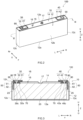
- FIG. 1 is a perspective view schematically illustrating a power storage module 500 according to an embodiment.
- the power storage module 500 includes a plurality of power storage devices 100 that are disposed along an arrangement direction X and a plurality of busbars 200 that electrically connect the plurality of power storage devices 100 to each other.
- the power storage module 500 further includes a restriction mechanism 300.
- reference signs L, R, F, Rr, U, and D in the drawings respectively denote left, right, front, rear, up, and down
- reference signs X, Y, and Z in the drawings respectively denote a thickness direction of the power storage device 100, a long side direction that is orthogonal to the thickness direction, and an up-down direction that is orthogonal to the thickness direction and the long side direction.
- the thickness direction X also corresponds to the arrangement direction of the power storage devices 100.
- the restriction mechanism 300 is configured to apply prescribed restriction pressure on the plurality of power storage devices 100 from the arrangement direction X.
- the restriction mechanism 300 here includes a pair of end plates 310, a pair of side plates 320, and a plurality of screws 330.
- the pair of end plates 310 are disposed at both ends of the plurality of power storage devices 100 in the arrangement direction X.
- the pair of end plates 310 hold the plurality of power storage devices 100 therebetween in the arrangement direction X.
- the pair of end plates 310 are preferably made of metal.
- the pair of side plates 320 link between the pair of end plates 310.
- the pair of side plates 320 are preferably made of metal.
- the pair of side plates 320 are fixed to the end plates 310 by the plurality of screws 330 so that a restriction load is generally about 10 to 15 kN, for example.
- the restriction load is applied on the plurality of power storage devices 100 from the arrangement direction X and accordingly, the power storage module 500 is held integrally.
- the structure of the restriction mechanism is, however, not limited to this example.
- the restriction mechanism 300 may alternatively include a plurality of restriction bands, bind bars, or the like instead of the side plates 320.
- the busbar 200 is a conductive member and electrically connects the plurality of power storage devices 100 to each other.
- the busbar 200 is formed of, for example, a conductive metal such as aluminum, an aluminum alloy, nickel, or stainless steel.
- the busbar 200 is preferably formed of aluminum or an aluminum alloy.
- the busbar 200 is provided to link between a positive electrode terminal 30 (see FIG. 2 , specifically a positive electrode first conductive member 31) and a negative electrode terminal 40 (see FIG. 2 , specifically a negative electrode first conductive member 41), which will be described below, of the power storage devices 100 that are adjacent in the arrangement direction X.
- the busbar 200 is attached to each of the positive electrode terminal 30 and the negative electrode terminal 40 by welding such as laser welding, for example.
- the power storage device 100 is a device that can store electric power and is capable of being charged and discharged repeatedly.
- the term "power storage device” refers to a concept encompassing so-called secondary batteries such as lithium ion secondary batteries and nickel-hydrogen batteries and capacitors such as lithium ion capacitors and electrical double-layer capacitors.
- the plurality of power storage devices 100 are arranged along the arrangement direction X (in other words, the thickness direction X of the power storage device 100) between the pair of end plates 310.
- the shape, the size, the number, the arrangement, and the like of the plurality of power storage devices 100 included in the power storage module 500 are not limited to the aspect disclosed herein, and can be changed as appropriate.
- a different member such as a spacer can exist between the power storage devices 100 that are adjacent in the arrangement direction X.
- the plurality of power storage devices 100 are connected to each other in series.
- the connection method between the plurality of power storage devices 100 is not limited to the series connection and may be, for example, parallel connection, multiple series-multiple parallel connection, or the like.
- FIG. 2 is a perspective view of the power storage device 100.
- FIG. 3 is a schematic longitudinal cross-sectional view taken along line III-III in FIG. 2 .
- the power storage device 100 includes a battery case 10, an electrode body 20, the positive electrode terminal 30, the negative electrode terminal 40, a positive electrode current collecting member 50, and a negative electrode current collecting member 60.
- the power storage device 100 further includes a nonaqueous electrolyte solution (not illustrated) here.
- the nonaqueous electrolyte solution may be similar to the conventional nonaqueous electrolyte solution, without particular limitations.
- the power storage device 100 is a lithium ion secondary battery here.
- the power storage device 100 is characterized by including the positive electrode terminal 30 and/or the negative electrode terminal 40 disclosed herein, and the other configurations may be similar to those in the related art.
- the battery case 10 is a housing that accommodates the electrode body 20 and the nonaqueous electrolyte solution.
- the external shape of the battery case 10 is a flat and bottomed cuboid shape (rectangular shape) here.
- a conventionally used material can be used for the battery case 10, without particular limitations.
- the battery case 10 is preferably made of metal, for example, more preferably made of aluminum, an aluminum alloy, iron, an iron alloy, or the like, and particularly preferably made of aluminum or an aluminum alloy.
- the battery case 10 includes an exterior body 12 including an opening 12h and a sealing plate (lid body) 14 that seals the opening 12h.
- the battery case 10 preferably includes the exterior body 12 and the sealing plate 14.
- the exterior body 12 includes a bottom wall 12a with a substantially rectangular shape facing the opening 12h (see FIG. 3 ), a pair of long side walls 12b extending from long sides of the bottom wall 12a and facing each other, and a pair of short side walls 12c extending from short sides of the bottom wall 12a and facing each other.
- the long side wall 12b is larger in area than the short side wall 12c.
- substantially rectangular shape encompasses, in addition to a perfect rectangular shape (rectangle), for example, a shape whose corner connecting a long side and a short side of the rectangular shape is rounded, a shape whose corner includes a notch, and the like.
- the sealing plate 14 is a plate-shaped member expanding along an XY plane in FIG. 2 .
- the sealing plate 14 is one example of "first surface”. As illustrated in FIG. 3 , the sealing plate 14 is attached to the exterior body 12 so as to cover the opening 12h.
- the sealing plate 14 faces the bottom wall 12a of the exterior body 12.
- the sealing plate 14 here is substantially rectangular in shape. It is preferable that the sealing plate 14 be substantially rectangular in shape.
- the battery case 10 is unified in a manner that the sealing plate 14 is joined (preferably, joined by welding) to a periphery of the opening 12h of the exterior body 12.
- the battery case 10 is hermetically sealed (closed).
- a liquid injection hole 15, a discharge valve 17, and two terminal extraction holes 18 and 19 are provided in the sealing plate 14.
- the liquid injection hole 15 is provided for the purpose of injecting the nonaqueous electrolyte solution after the sealing plate 14 is assembled to the exterior body 12.
- the liquid injection hole 15 is sealed by a sealing member 16.
- the discharge valve 17 is configured to break when the pressure in the battery case 10 becomes more than or equal to a predetermined value so as to discharge the gas out of the battery case 10.
- the terminal extraction holes 18 and 19 penetrate the sealing plate 14 in the up-down direction Z.
- the terminal extraction holes 18 and 19 are one example of "penetration hole” provided to the sealing plate 14 (first surface).
- the terminal extraction holes 18 and 19 are formed in an annular shape (for example, circular shape).
- the terminal extraction hole 18 has the inner diameter that enables a shaft column part 32s of the positive electrode terminal 30 to be described below before a caulking process (before being attached to the sealing plate 14) to pass therethrough.
- the terminal extraction hole 19 has the inner diameter that enables a shaft column part 42s of the negative electrode terminal 40 to be described below before the caulking process (before being attached to the sealing plate 14) to pass therethrough.
- the electrode body 20 is accommodated inside the battery case 10 (in detail, the exterior body 12).
- the electrode body 20 includes a positive electrode and a negative electrode.
- the positive electrode includes a positive electrode current collector, and a positive electrode mixture layer fixed on the positive electrode current collector and including a positive electrode active material.
- the negative electrode includes a negative electrode current collector, and a negative electrode mixture layer fixed on the negative electrode current collector and including a negative electrode active material.
- One of the positive electrode and the negative electrode is one example of "first electrode” and the other is one example of "second electrode”.
- the first electrode is the negative electrode and the second electrode is the positive electrode.
- the first electrode is preferably the negative electrode and the second electrode is preferably the positive electrode.
- the structure of the electrode body 20 may be similar to the conventional structure thereof, without particular limitations.
- the electrode body 20 here is a wound electrode body with a flat shape in which the positive electrode with a band shape and the negative electrode with a band shape are stacked via a separator in an insulated state and wound using a winding axis as a center.
- the electrode body 20 may be a stack type electrode body formed in a manner that a plurality of square positive electrodes and a plurality of square negative electrodes are stacked in the insulated state.
- the number of electrode bodies 20 to be disposed in one battery case 10 is not limited in particular and may be one or plural.
- a positive electrode current collecting part 23 is provided at one end part of the electrode body 20 in a winding axis direction (the long side direction Y in FIG. 3 ) (left end part in FIG. 3 ).
- the positive electrode current collecting part 23 is an exposed part of the positive electrode current collector in this case, and is formed of, for example, a conductive metal such as aluminum, an aluminum alloy, nickel, or stainless steel.
- a second part 52 of the positive electrode current collecting member 50 to be described below is attached to the positive electrode current collecting part 23, a second part 52 of the positive electrode current collecting member 50 to be described below is attached.
- a negative electrode current collecting part 25 is provided at the other end part of the electrode body 20 in the winding axis direction (right end part in FIG. 3 ).
- the negative electrode current collecting part 25 is an exposed part of the negative electrode current collector in this case, and is formed of, for example, a conductive metal such as copper, a copper alloy, nickel, or stainless steel. To the negative electrode current collecting part 25, a second part 62 of the negative electrode current collecting member 60 to be described below is attached.
- the positive electrode current collecting member 50 constitutes a conductive path that electrically connects the positive electrode terminal 30 and the positive electrode (second electrode) of the electrode body 20.
- the positive electrode current collecting member 50 is preferably formed of the same metal species as the positive electrode current collecting part 23, for example, a conductive metal such as aluminum, an aluminum alloy, nickel, or stainless steel.
- the positive electrode current collecting member 50 includes a first part 51 with a substantially L-like shape, and the second part 52 electrically connected to the first part 51 and extending along the short side wall 12c of the exterior body 12.
- the first part 51 is attached to an inner surface of the sealing plate 14 by the caulking process in an insulated state through an internal insulating member 70.
- the first part 51 is electrically connected to the positive electrode terminal 30.
- the second part 52 is attached to the positive electrode current collecting part 23.
- the negative electrode current collecting member 60 constitutes a conductive path that electrically connects the negative electrode terminal 40 and the negative electrode (first electrode) of the electrode body 20.
- the negative electrode current collecting member 60 is preferably formed of the same metal species as the negative electrode current collecting part 25, for example, a conductive metal such as copper, a copper alloy, nickel, or stainless steel.
- the negative electrode current collecting member 60 includes a first part 61 with a substantially L-like shape, and the second part 62 electrically connected to the first part 61 and extending along the short side wall 12c of the exterior body 12.
- the first part 61 is attached to the inner surface of the sealing plate 14 by the caulking process in the insulated state through the internal insulating member 70.
- the first part 61 is electrically connected to the negative electrode terminal 40.
- the second part 62 is attached to the negative electrode current collecting part 25.
- FIG. 4 is a perspective view schematically illustrating a united object in which the positive electrode terminal 30, the negative electrode terminal 40, the first part 51 of the positive electrode current collecting member 50, and the first part 61 of the negative electrode current collecting member 60 are attached to a sealing plate assembly, that is, the sealing plate 14.
- the positive electrode terminal 30 and the negative electrode terminal 40 are preferably attached to the sealing plate 14.
- the positive electrode terminal 30 is disposed at an end part of the sealing plate 14 on one side in the long side direction Y (left end part in FIG. 2 to FIG. 4 ). As illustrated in FIG. 3 , the positive electrode terminal 30 is electrically connected to the positive electrode (second electrode) of the electrode body 20 through the positive electrode current collecting member 50.
- the positive electrode terminal 30 includes two kinds of conductive members, that is, the positive electrode first conductive member 31 and a positive electrode second conductive member 32.
- the positive electrode first conductive member 31 and the positive electrode second conductive member 32 are integrated and electrically connected to each other.
- the positive electrode first conductive member 31 is disposed outside the battery case 10.
- the positive electrode first conductive member 31 here has a plate shape.
- the positive electrode first conductive member 31 is insulated from an outer surface of the sealing plate 14 (upper surface in FIG. 3 ) by an external insulating member 90.
- the busbar 200 is attached to the positive electrode first conductive member 31.
- the positive electrode second conductive member 32 penetrates the terminal extraction hole 18 and extends from inside to outside of the battery case 10.
- the positive electrode second conductive member 32 includes the shaft column part 32s that is disposed in the terminal extraction hole 18.
- the positive electrode second conductive member 32 is insulated from the sealing plate 14 by the internal insulating member 70 and a gasket 80.
- the gasket 80 insulates the sealing plate 14 and the positive electrode second conductive member 32 and moreover, has a function that closes the terminal extraction hole 18.
- the positive electrode second conductive member 32 is fixed by caulking to a peripheral part of the sealing plate 14 that surrounds the terminal extraction hole 18 in the state of being insulated from the sealing plate 14 by the caulking process.
- a caulking part 30c is formed at an end part of the positive electrode second conductive member 32 on the exterior body 12 side (lower end part in FIG. 3 ).
- the positive electrode second conductive member 32 is fixed to the sealing plate 14 by the caulking process and moreover, electrically connected to the first part 51.
- the negative electrode terminal 40 is disposed at an end part of the sealing plate 14 on the other side in the long side direction Y (right end part in FIG. 2 to FIG. 4 ). As illustrated in FIG. 3 , the negative electrode terminal 40 is electrically connected to the negative electrode (first electrode) of the electrode body 20 through the negative electrode current collecting member 60.
- the negative electrode terminal 40 is one example of "first electrode terminal that is electrically connected to the negative electrode (first electrode)".
- the first electrode terminal is preferably the negative electrode terminal 40.
- the first electrode terminal may be the positive electrode terminal 30. In that case, "negative electrode” can be replaced by "positive electrode” as appropriate in the description below.
- FIG. 5 is a plan view schematically illustrating a vicinity of the negative electrode terminal 40 in FIG. 4 .
- FIG. 6 is a schematic longitudinal cross-sectional view taken along line VI-VI in FIG. 4 and FIG. 5 .
- FIG. 7 is a schematic longitudinal cross-sectional view illustrating only the negative electrode terminal 40 in FIG. 6 .
- the negative electrode terminal 40 includes two kinds of conductive members, that is, the negative electrode first conductive member 41 and a negative electrode second conductive member 42.
- the negative electrode first conductive member 41 is one example of "first conductive member”.
- the negative electrode second conductive member 42 is one example of "second conductive member”.
- the negative electrode first conductive member 41 and the negative electrode second conductive member 42 are integrated by a fastening part 43 and a metal joined part 45, which will be described below, so as to be connected electrically to each other.
- the fastening part 43 is not essential and may be omitted in another embodiment.
- the negative electrode first conductive member 41 is formed of, for example a conductive metal such as aluminum, an aluminum alloy, nickel, or stainless steel.
- the negative electrode first conductive member 41 preferably contains aluminum or an aluminum alloy.
- the negative electrode first conductive member 41 is preferably formed of aluminum or an aluminum alloy at least in the vicinity of the metal joined part 45.
- the negative electrode first conductive member 41 is preferably formed of aluminum or an aluminum alloy.
- the negative electrode first conductive member 41 is mainly formed of a first metal. In other words, the first metal occupies the maximum ratio on the mass basis.
- the first metal occupies preferably 50 mass% or more, more preferably 70 mass% or more, and particularly preferably 90 mass% or more of the entire negative electrode first conductive member 41 (however, excluding a part where the metal joined part 45 is formed).
- the first metal is preferably aluminum.
- the first metal is preferably the same metal species as the busbar 200.
- the negative electrode first conductive member 41 is disposed outside the battery case 10.
- the negative electrode first conductive member 41 has a plate shape here. As illustrated in FIG. 6 , the negative electrode first conductive member 41 is insulated from the outer surface (upper surface in FIG. 6 ) of the sealing plate 14 by the external insulating member 90. Between the negative electrode first conductive member 41 and the sealing plate 14, the external insulating member 90 is preferably disposed.
- the external insulating member 90 is preferably a resin member.
- the negative electrode first conductive member 41 has a substantially rectangular shape here.
- the negative electrode first conductive member 41 has two parts sectioned in the long side direction Y: a connection part 41a electrically connected to the negative electrode second conductive member 42; and an extension part 41b disposed on one side of the connection part 41a in the long side direction Y (on the left in FIG. 5 ).
- the extension part 41b is a part where the busbar 200 is disposed when the power storage module 500 (see FIG. 1 ) is manufactured.
- the extension part 41b is one example of "busbar connection region".
- the negative electrode first conductive member 41 has a flat plate shape and includes a lower surface 41d and an upper surface 41u here.
- the lower surface 41d is in contact with the negative electrode second conductive member 42.
- the lower surface 41d is a surface that faces the battery case 10 (specifically, sealing plate 14).
- the upper surface 41u is a surface apart from the battery case 10 and the negative electrode second conductive member 42.
- the negative electrode first conductive member 41 includes a thin part 41t that is depressed from the upper surface 41u to be thinner than the extension part 41b, a penetration hole 41h penetrating in the up-down direction Z, and a concave part 41r depressed from the lower surface 41d.
- the thin part 41t is formed in an annular shape (for example, circular shape) so as to surround the penetration hole 41h in a plan view.
- the metal joined part 45 is provided in the thin part 41t.
- the penetration hole 41h is formed at a center part of the thin part 41t in a plan view.
- the penetration hole 41h can function as an escape route of distortion by gas or heat generated at welding.
- the penetration hole 41h is formed to be circular in a plan view.
- the penetration hole 41h is provided on an inner peripheral side relative to the fastening part 43 and the metal joined part 45. From the penetration hole 41h, the negative electrode second conductive member 42 (specifically, a flange part 42f to be described below) is exposed.
- the concave part 41r is provided on an outer peripheral side relative to the metal joined part 45.
- the concave part 41r is formed in an annular shape (for example, circular shape) in a plan view.
- the concave part 41r is formed in a tapered shape whose diameter reduces toward the lower surface 41d of the negative electrode first conductive member 41 (in other words, toward the negative electrode second conductive member 42) here.
- the fastening part 43 is provided in the concave part 41r.
- a constriction part 42n of the negative electrode second conductive member 42 which is described below, is inserted.
- the negative electrode second conductive member 42 is formed of, for example, a conductive metal such as copper, a copper alloy, nickel, or stainless steel.
- the negative electrode second conductive member 42 preferably contains copper or a copper alloy.
- the negative electrode second conductive member 42 is preferably formed of copper or a copper alloy at least in the vicinity of the metal joined part 45.
- the negative electrode second conductive member 42 is preferably formed of copper or a copper alloy.
- the negative electrode second conductive member 42 is mainly formed of a second metal. In other words, the second metal occupies the maximum ratio on the mass basis.
- the second metal occupies preferably 50 mass% or more, more preferably 70 mass% or more, and particularly preferably 90 mass% or more of the entire negative electrode second conductive member 42 (however, excluding a part where the metal joined part 45 is formed).
- the second metal is particularly preferably copper.
- the second metal is preferably a metal with higher hardness (for example, Vickers hardness (HV)) than the first metal.
- the second metal is preferably the same metal species as the negative electrode current collecting part 25 and/or the negative electrode current collecting member 60.
- the negative electrode second conductive member 42 may include a metal covered part that is formed of copper or a copper alloy mainly and has a surface thereof partially or entirely covered with metal such as Ni. Thus, the resistance against an electrolyte can be increased and the corrosion resistance can be improved.
- the negative electrode second conductive member 42 penetrates the terminal extraction hole 19 and extends from inside to outside of the battery case 10.
- the negative electrode second conductive member 42 is insulated from the sealing plate 14 by the internal insulating member 70 and the gasket 80.
- the gasket 80 insulates the sealing plate 14 and the negative electrode second conductive member 42 and moreover, has a function that closes the terminal extraction hole 19.
- the negative electrode second conductive member 42 is fixed by caulking to a peripheral part of the sealing plate 14 that surrounds the terminal extraction hole 19 in the state of being insulated from the sealing plate 14 by the caulking process.
- a caulking part 40c is formed at an end part of the negative electrode second conductive member 42 on the exterior body 12 side (lower end part in FIG. 6 ).
- the negative electrode second conductive member 42 is fixed to the sealing plate 14 by the caulking process and moreover, electrically connected to the first part 61.
- the negative electrode second conductive member 42 has a substantially cylindrical columnar shape here.
- the negative electrode second conductive member 42 preferably has a columnar shape. As illustrated in FIG. 7 , the negative electrode second conductive member 42 has an axial center C.
- the negative electrode second conductive member 42 includes the flange part 42f electrically connected to the negative electrode first conductive member 41, and the shaft column part 42s coupled to a lower end part of the flange part 42f.
- the negative electrode second conductive member 42 preferably has the flange part 42f on an upper part and the shaft column part 42s below the flange part 42f.
- the flange part 42f is a part that protrudes from the terminal extraction hole 19 of the sealing plate 14 to the outside of the battery case 10 as illustrated in FIG. 6 .
- the flange part 42f has a larger outer shape than the shaft column part 42s.
- the outer shape of the flange part 42f is substantially cylindrical columnar here.
- the outer shape of the flange part 42f is larger than that of the terminal extraction hole 19 of the sealing plate 14.
- an axial center of the flange part 42f coincides with the axial center C of the negative electrode second conductive member 42.
- the flange part 42f includes a lower surface 42d, a side surface (outer peripheral surface) 42o extending upward from the lower surface 42d, the constriction part 42n in which a part of the side surface 42o is constricted, and an upper surface 42u.
- the upper surface 42u is in contact with the concave part 41r of the negative electrode first conductive member 41.
- the metal joined part 45 is provided on the upper surface 42u.
- the constriction part 42n is provided continuously or intermittently in a part of the side surface 42o of the flange part 42f as illustrated in FIG. 7 .
- the constriction part 42n is formed in an annular shape (for example, circular shape) in a plan view.
- the fastening part 43 with high strength can be formed.
- the constriction part 42n is formed axially symmetrically about the axial center C of the flange part 42f.
- the constriction part 42n is formed in an inverted tapered shape whose diameter increases toward the upper surface 41u (in other words, away from the shaft column part 42s).
- the fastening part 43 is provided in the constriction part 42n.
- the constriction part 42n is inserted into the concave part 41r of the negative electrode first conductive member 41.
- the constriction part 42n is fitted into the concave part 41r of the negative electrode first conductive member 41 and engaged with the concave part 41r here.
- the shaft column part 42s extends downward from the lower end part of the flange part 42f.
- the shaft column part 42s is one example of "shaft part".
- the shaft column part 42s has a cylindrical shape here.
- An axial center of the shaft column part 42s coincides with the axial center C of the flange part 42f.
- the lower end part of the shaft column part 42s that is, an end part on the opposite side of the flange part 42f is hollow.
- the shaft column part 42s is disposed in the terminal extraction hole 19 of the sealing plate 14.
- the lower end part of the shaft column part 42s is spread by the caulking process to form the caulking part 40c.
- the shaft column part 42s is electrically connected to the first part 61 of the negative electrode current collecting member 60 by the caulking process.
- the fastening part 43 is a mechanical fixing part for the negative electrode first conductive member 41 and the negative electrode second conductive member 42.
- the fastening part 43 is a mechanical fixing part for the concave part 41r and the flange part 42f (specifically, constriction part 42n).
- a formation method for the fastening part 43 is not limited in particular as long as mechanical joining with mechanical energy is used, and may be, for example, press-fitting, caulking, shrink-fitting, riveting, folding, bolt joining, or the like.
- the fastening part 43 is provided at the lower surface 41d of the negative electrode first conductive member 41 as illustrated in FIG. 6 .
- the fastening part 43 is an engagement part where the concave part 41r of the negative electrode first conductive member 41 and the constriction part 42n of the negative electrode second conductive member 42 are engaged here.
- the fastening part 43 is a press-fitting engagement part where the constriction part 42n of the negative electrode second conductive member 42 is engaged with the concave part 41r of the negative electrode first conductive member 41 by press-fitting.
- the fastening part 43 is configured in a manner that an inner wall of the concave part 41r of the negative electrode first conductive member 41 is fixed (for example, fixed by pressure) with the constriction part 42n of the negative electrode second conductive member 42.
- an inner wall of the concave part 41r of the negative electrode first conductive member 41 is fixed (for example, fixed by pressure) with the constriction part 42n of the negative electrode second conductive member 42.
- the fastening part 43 is provided on an outer peripheral side of the flange part 42f relative to the metal joined part 45 here. Although not illustrated, the fastening part 43 is formed in an annular shape (for example, circular shape) in a plan view. The fastening part 43 is formed continuously here. Thus, the strength of the fastening part 43 can be increased and the conduction reliability of the negative electrode terminal 40 can be improved further.
- the metal joined part 45 is a metallurgic joined part between the negative electrode first conductive member 41 and the negative electrode second conductive member 42.
- the metal joined part 45 is a joined part between the thin part 41t and the flange part 42f here.
- the metal joined part 45 includes a fused and solidified part, which is formed in a manner that the negative electrode first conductive member 41 and the negative electrode second conductive member 42 are melted by irradiation with an energy beam, fused, and solidified.
- the fused and solidified part can be formed by using, for example, light energy, electron energy, thermal energy, or the like. In particular, welding is preferable. The welding can achieve the metal joined part 45 with high strength relatively easily and stably.
- a method of the welding is not limited in particular and may be, for example, laser welding, electron beam welding, ultrasonic welding, resistance welding, tungsten inert gas (TIG) welding, or the like.
- the metal joined part 45 is preferably a laser welding part formed by laser welding. Note that a suitable condition of the laser welding will be discussed in a manufacturing method below.
- the metal joined part 45 is provided on the upper surface 41u of the negative electrode first conductive member 41.
- the metal joined part 45 is provided at a position apart from the penetration hole 41h.
- the metal joined part 45 is provided on an outer peripheral side of the penetration hole 41h.
- the metal joined part 45 is provided at a position apart from the fastening part 43.
- the metal joined part 45 can be a joined part with relatively higher stiffness than the fastening part 43, for example.
- the metal joined part 45 is provided on the inner peripheral side (on a center side of the flange part 42f) relative to the fastening part 43 in a plan view here. In other words, the metal joined part 45 is provided closer to a center 42c of the negative electrode second conductive member 42.
- the metal joined part 45 can be a joined part with relatively lower strength (fragile) than the fastening part 43.
- the metal joined part 45 is provided in the thin part 41t here. Thus, the energy at the joining can be saved and the weldability can be improved.
- the metal joined part 45 is formed continuously or intermittently.
- the metal joined part 45 is formed axially symmetrically about the axial center C of the flange part 42f. Thus, the strength of the metal joined part 45 can be increased and the conduction reliability of the negative electrode terminal 40 can be improved further.
- the metal joined part 45 is formed in an annular shape (for example, circular shape) in a plan view.
- the metal joined part 45 is provided so as to surround the center 42c of the flange part 42f along the entire circumference here.
- the metal joined part 45 is provided so as to surround an outer edge of the penetration hole 41h using the axial center C of the flange part 42f as a center.
- the metal joined part 45 is distinguished as follows: a metal joined part 45A on a side closer to the extension part 41b (on the left side in FIG. 7 ); and a metal joined part 45B on a side farther from the extension part 41b (on the right side in FIG. 7 ).
- FIG. 8 is a magnified view schematically illustrating the vicinity of the metal joined part 45A on the side closer to the extension part 41b in FIG. 7 (on the left side in FIG. 7 ).
- the metal joined part 45 includes a first region 451 and a second region 452.
- the negative electrode terminal 40 includes a border surface B passing a border part where the negative electrode first conductive member 41 and the negative electrode second conductive member 42 are in contact with each other around the metal joined part 45.
- the border surface B extends in a direction parallel to the sealing plate 14 (specifically, the outer surface of the sealing plate 14 or the inner surface of the sealing plate 14). In FIG. 8 , the border surface B passes the metal joined part 45.
- the border surface B roughly divides the metal joined part 45 into the negative electrode first conductive member 41 side (upper side in FIG. 8 ) and the negative electrode second conductive member 42 side (lower side in FIG. 8 ).
- the cross section is a first cross section (cross section taken along line VI-VI in FIG. 4 and FIG. 5 ) passing the axial center C of the negative electrode second conductive member 42 and extending along the long side direction Y of the sealing plate 14 (first surface).
- the aforementioned cross section may be a second cross section with the smallest angle with the first cross section among the cross sections passing the axial center C of the negative electrode second conductive member 42 and extending in the radial direction of the negative electrode second conductive member 42.
- the first region 451 is a region where the first metal (here, Al) occupies 70 mass% or more.
- the first region 451 can be a region where the metal (mainly, second metal) included in the negative electrode second conductive member 42 is melted in the negative electrode first conductive member 41.
- the strength for example, tensile strength
- the first region 451 exists mostly on the negative electrode first conductive member 41 side (upper side in FIG. 8 ) relative to the border surface B and partially protrudes toward the negative electrode second conductive member 42 (lower side in FIG. 8 ).
- the first region 451 includes a region A1 existing on the negative electrode first conductive member 41 side (upper side in FIG. 8 ) relative to the border surface B and a first protrusion region P1 protruding toward the negative electrode second conductive member 42 (lower side in FIG. 8 ) relative to the border surface B.
- the second region 452 is a region where the second metal (here, Cu) occupies 70 mass% or more.
- the second region 452 can be a region where the metal (mainly, first metal) included in the negative electrode first conductive member 41 is melted in the negative electrode second conductive member 42.
- the strength for example, tensile strength
- the second region 452 exists mostly on the negative electrode second conductive member 42 side (lower side in FIG. 8 ) relative to the border surface B and partially protrudes toward the negative electrode first conductive member 41 (upper side in FIG. 8 ).
- the second region 452 includes a region A2 existing on the negative electrode second conductive member 42 side (lower side in FIG. 8 ) relative to the border surface B and a second protrusion region P2 protruding toward the negative electrode first conductive member 41 (upper side in FIG. 8 ) relative to the border surface B.
- the first region 451 includes the first protrusion region P1
- the second region 452 includes the second protrusion region P2
- a border between the first region 451 and the second region 452 has an uneven shape.
- a border part between the first region 451 and the second region 452 is slippery and has low strength in general; however, when the border part has such an uneven shape and the negative electrode first conductive member 41 and the negative electrode second conductive member 42 are engaged with each other mechanically, the border part becomes less slippery and the joining strength (for example, tensile strength) can be improved. Additionally, by bending the border part, the distance of the border part can be extended; thus, even in the occurrence of a crack in the metal joined part 45, the development of the crack can be slowed down.
- the close contact state between the negative electrode first conductive member 41 and the negative electrode second conductive member 42 can be kept easily and the conductive connection between the negative electrode first conductive member 41 and the negative electrode second conductive member 42 can be kept stably.
- the metal joined part 45 where the first region 451 includes the first protrusion region P1 and the second region 452 includes the second protrusion region P2 can be achieved by performing circumferential welding (wobbling) at the welding, for example, as illustrated in FIG. 8 , which will be described in detail below.
- a ratio C1 of the area of the first protrusion region P1 to the total area of the first region 451 is preferably 0.01 to 0.4 (1 to 40%) and more preferably 0.03 to 0.2 (3 to 20%).
- a ratio C2 of the area of the second protrusion region P2 to the total area of the second region 452 is preferably 0.03 to 0.5 (3 to 50%) and more preferably 0.05 to 0.3 (5 to 30%).
- the ratio C2 of the area of the second protrusion region P2 is preferably larger than the ratio C1 of the area of the first protrusion region P1. Note that the aforementioned ratios C1 and C2 of the areas can be achieved by adjusting the conditions of the welding to be described below (for example, output of laser, frequency or width of wobbling, or the like).
- a part of the border surface B that passes the metal joined part 45 is a line LB.
- the strength for example, tensile strength
- the durability of the metal joined part 45 can be improved.
- the second protrusion region P2 is preferably disposed closer to the fastening part 43 than the first protrusion region P1 at the cross section (here, cross section taken along line VI-VI in FIG. 4 and FIG. 5 ) being perpendicular to the sealing plate 14 (first surface), passing the axial center C of the shaft column part 42s, and extending in the radial direction of the shaft column part 42s as illustrated in FIG. 8 .
- the metal joined part 45 starts to be broken from the fastening part 43 side. Therefore, by arranging the second protrusion region P2 containing a large amount of second metal with relative high hardness (here, Cu) closer to the fastening part 43 than the first protrusion region P 1 containing a large amount of first metal with relative low hardness (here, Al), the strength (for example, tensile strength) and the durability of the metal joined part 45 can be improved. Note that the positional relation between the first protrusion region P1 and the second protrusion region P2 can be adjusted by the condition of the welding (specifically, direction of rotation of wobbling) to be described below.
- the second protrusion region P2 be disposed closer to the extension part 41b (busbar connection region) than the first protrusion region P1 at the cross section being perpendicular to the sealing plate 14 (first surface) and extending along the long side direction Y of the sealing plate 14 (first surface) as illustrated in FIG. 8 .
- the second protrusion region P2 be disposed closer to the extension part 41b than the first protrusion region P1 in the metal joined part 45A on the side close to the extension part 41b (on the left side in FIG. 7 ).
- the metal joined part 45 starts to be broken from the extension part 41b side. Therefore, by arranging the second protrusion region P2 containing a large amount of second metal with relative high hardness (here, Cu) closer to the extension part 41b than the first protrusion region P1 containing a large amount of first metal with relative low hardness (here, Al), the strength (for example, tensile strength) and the durability of the metal joined part 45 can be improved. Note that the positional relation between the first protrusion region P1 and the second protrusion region P2 can be adjusted by the condition of the welding (specifically, direction of rotation of wobbling) to be described below.
- the metal joined part 45 additionally includes a third region 453 at the border between the first region 451 and the second region 452.
- the third region 453 is a region where the first metal is contained by 30 mass% or more and less than 70 mass% and the second metal is contained by 30 mass% or more and less than 70 mass%.
- the third region 453 is not always necessary and can be omitted in another embodiment.
- the negative electrode terminal 40 as described above can be manufactured by, for example, preparing the negative electrode first conductive member 41 and the negative electrode second conductive member 42 as described above and performing a manufacturing method including a fastening step and a welding joining step.
- a manufacturing method including a fastening step and a welding joining step is not limited in particular; however, from the viewpoint of suppressing the damage of the metal joined part 45 when the fastening part 43 is formed, the welding joining step is performed preferably after the fastening step.
- the fastening step may be performed after the welding joining step or both steps may be performed at substantially the same time.
- the manufacturing method disclosed herein may further include another step at an optional stage.
- the negative electrode first conductive member 41 and the flange part 42f of the negative electrode second conductive member 42 are mechanically fixed so as to form the fastening part 43.
- the fastening part 43 can be formed in a manner that, for example, the constriction part 42n of the negative electrode second conductive member 42 is inserted into the concave part 41r of the negative electrode first conductive member 41 and the concave part 41r of the negative electrode first conductive member 41 is deformed along the outer shape of the constriction part 42n of the negative electrode second conductive member 42, so that the inner wall of the concave part 41r is fixed by the negative electrode second conductive member 42.
- the strength of the fastening part 43 can be improved.
- the fastening part 43 is formed by engaging the concave part 41r of the negative electrode first conductive member 41 and the constriction part 42n of the negative electrode second conductive member 42.
- the fastening part 43 can be formed by horizontally press-fitting the constriction part 42n of the negative electrode second conductive member 42 into the concave part 41r of the negative electrode first conductive member 41.
- the thin part 41t of the negative electrode first conductive member 41 and the flange part 42f of the negative electrode second conductive member 42 are joined by welding; thus, the metal joined part 45 is formed.
- the metal joined part 45 can be formed in a manner that, for example, the thin part 41t of the negative electrode first conductive member 41 and the flange part 42f of the negative electrode second conductive member 42 are stacked, an energy beam is delivered from the negative electrode first conductive member 41 (thin part 41t) side, and welding is performed so that the energy reaches at least the upper surface 42u of the flange part 42f through the thin part 41t.
- the welding is preferably performed by the method as described above, for example the laser welding.
- FIG. 9A is an explanatory view for describing a method of the laser welding in the case of forming the annular metal joined part 45 as illustrated in FIG. 5 .
- FIG. 9A illustrates only a part of the thin part 41t for which the welding is performed in a plan view.
- the annular metal joined part 45 may be formed as follows: welding starts from a welding start point (1), the whole laser travels clockwise and the rotation of the wobbling progresses counterclockwise, and thus, the laser light is delivered so as to draw an annular trace to a welding end point (2) while surrounding the outer edge of the penetration hole 41h as illustrated in FIG. 9A .
- the conditions of the welding are design matters that can be adjusted as appropriate in accordance with, for example, the materials of the negative electrode first conductive member 41 and the negative electrode second conductive member 42, the thickness of the negative electrode first conductive member 41, and the like.
- the output of the laser is preferably about 500 to 1500 W, more preferably 1300 W or less, and still more preferably 600 to 1000 W.
- the welding speed is preferably about 10 to 1000 mm/s and more preferably 50 to 100 mm/s.
- the frequency of the wobbling is preferably about 1000 Hz or less, and for example, 100 to 600 Hz.
- the width of the wobbling is preferably 0.1 to 10 mm, and more preferably 0.2 to 1 mm, for example.
- FIG. 9B is a schematic longitudinal cross-sectional view in the vicinity of the metal joined parts 45A and 45B taken along line IXB-IXB in FIG. 9A .
- the second protrusion region P2 is disposed closer to the extension part 41b than the first protrusion region P1 in the metal joined part 45A on the side close to the extension part 41b at the cross section (cross section taken along line IXB-IXB in FIG.
- the first protrusion region P1 is disposed closer to the extension part 41b than the second protrusion region P2.
- the metal joined part 45 is formed on the inner peripheral side relative to the fastening part 43 here.
- the joined place is displaced less easily and the workability in the welding joining step can be improved.
- the welding place shakes less easily when the metal joined part 45 is formed and thus, the weldability can be improved.
- the thin part 41t is welded, the energy can be saved and the weldability can be improved.
- the power storage device 100 and the power storage module 500 can be used for various applications, and can be suitably used in an application in which an external force such as vibration or impact may be applied during the use thereof and typically, used as a motive power source (driving power source) for a motor mounted on various vehicles such as a passenger car or a truck.
- a motive power source driving power source
- passenger cars is not particularly limited, examples thereof may include a plug-in hybrid electric vehicle (PHEV), a hybrid electric vehicle (HEV), a battery electric vehicle (BEV), and the like.
- a first conductive member with a plate shape (material: aluminum (A1050)) and a second conductive member with a cylindrical shape (material: copper (C1100)) were prepared.
- the first conductive member and the second conductive member were overlapped and irradiated with the single-mode fiber laser from the first conductive member side; thus, the welding was performed under conditions shown in Table 1. In this manner, the metal joined part was formed.
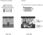
- Table 1 Conditions of laser welding Comparative Example Example Mode Linear welding Circumferential welding (wobbling) Output 600 W 1000 W Welding speed 60 mm/s 70 mm/s Conditions of wobbling - Frequency 400 Hz Width 0.7 mm
- Example and Comparative Example a part where the metal joined part was formed was cut at the cross section along the center of the metal joined part of the second conductive member and embedded and polished; thus, an observation sample was manufactured.
- the manufactured observation sample was subjected to an etching process using an etchant (etching solution in which ammonia water diluted to 14% and hydrogen peroxide solution diluted to 0.35% were mixed at a ratio of 1:1 and stirred) to change the color of the metal joined part, so that the border was made recognizable.
- etchant etching solution in which ammonia water diluted to 14% and hydrogen peroxide solution diluted to 0.35% were mixed at a ratio of 1:1 and stirred
- the observation sample was photographed using a scanning electron microscope (SEM) and a cross-sectional image was obtained. Note that the measurement conditions were as follows.
- the SEM observation images are shown in FIG. 10A and FIG. 10B . Although not illustrated, the obtained SEM observation images were analyzed using energy dispersive X-ray spectroscopy (EDX), so that the distributions of the metal elements (Al, Cu) were analyzed.
- EDX energy dispersive X-ray spectroscopy
- FIG. 10A illustrates a trace of the laser welding and is a cross-sectional SEM observation image of the metal joined part in Comparative Example
- FIG. 10B illustrates a trace of the laser welding and is a cross-sectional SEM observation image of the metal joined part in Example.
- the metal joined part in Comparative Example in which the linear welding was performed was formed so as to be narrower as getting away from the surface on the welded side (in other words, welding depth becomes deeper).
- the metal joined part disclosed herein can be suitably formed by, for example, the circumferential welding (wobbling).
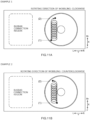
- FIG. 11A is a plan view of the negative electrode terminal schematically illustrating a trace of the laser welding in Example 1
- FIG. 11B is a plan view of the negative electrode terminal schematically illustrating a trace of the laser welding in Example 2.
- Example 1 in the laser welding, the welding started from the welding start point (1), the whole laser traveled from the lower side to the upper side (clockwise) in FIG. 11A and the rotation of the wobbling progressed clockwise, and thus, the laser light was delivered so as to draw a trace with a line shape to the welding end point (2) as illustrated in FIG. 11A .
- Example 2 in the laser welding, the welding started from the welding start point (1), the whole laser traveled from the lower side to the upper side (clockwise) in FIG. 11B and the rotation of the wobbling progressed counterclockwise (reverse rotation of Example 1), and thus, the laser light was delivered so as to draw a trace with a line shape to the welding end point (2) as illustrated in FIG. 11B .
- the output of the laser was changed to 800 W in Example 1 and Example 2.
- Example 2 The SEM observation of the metal joined parts formed in this manner indicates that the first protrusion region P1 existed closer to the busbar connection region (on the left side in FIG. 12 ) than the second protrusion region P2 in Example 1 as illustrated in FIG. 12 .
- the second protrusion region P2 existed closer to the busbar connection region than the first protrusion region P1.
- the positional relation between the first protrusion region P1 and the second protrusion region P2 is the same as that of the metal joined part 45 in FIG. 8 described in the aforementioned embodiment.
- Example 1 is an example of the metal joined part obtained by performing mirror inversion in a symmetrical manner on the metal joined part in Example 2.
- a busbar was welded to the extension part (busbar connection region) of the negative electrode terminal in each example.
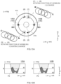
- a commercial tensile tester was prepared and the second conductive member was held with a clamp of the tensile tester. Then, based on JIS K 6854-1 (determination of peel strength of bonded assemblies-part 1: 90° peel), the busbar was pulled in a vertical direction (90°-direction) so as to peel the busbar from the first conductive member in the tensile tester, and the strength at which the metal joined part was broken was measured as the tensile strength (N). The results are expressed in FIG. 12 . Note that as the numeral of the tensile strength is higher, it means that the joining strength is higher.
- the tensile strength was relatively higher in Example 2 in which the second protrusion region P2 was disposed close to the busbar connection region than in Example 1 in which the first protrusion region P1 was disposed close to the busbar connection region. Therefore, it has been understood that the metal joined part can have higher strength and durability by disposing the second protrusion region P2 on the busbar connection region side.
- the metal joined part 45 was formed in the annular shape (for example, circular shape) in a plan view as illustrated in FIG. 5 . Moreover, the metal joined part 45 was formed by delivering the laser so as to draw the annular trace as illustrated in FIG. 9A .
- the present disclosure is not limited to this example.
- the metal joined part 45 may be formed in a C shape, a semi-circular arc shape, a double or more circular shape, a spiral shape, a linear shape, a dashed line shape, or the like in a plan view.
- the metal joined part 45 may be formed by performing the laser welding twice or more.
- FIG. 13A is a diagram corresponding to FIG. 9A in a first modification.
- the welding may start from the welding start point (1), the whole laser may travel clockwise and the rotation of the wobbling may progress clockwise, and thus, the laser light may be delivered so as to draw a semi-circular trace to the welding end point (2) along the outer edge of the penetration hole 41h as illustrated in FIG. 13A .
- the welding may start from a welding start point (3), the whole laser may travel clockwise and the rotation of the wobbling may progress counterclockwise (direction of rotation is changed), and the laser light may be delivered so as to draw a semi-circular trace to a welding end point (4) along the outer edge of the penetration hole 41h.
- FIG. 13B is a diagram corresponding to FIG. 9B in the first modification. If the laser light is delivered by changing the direction of the rotation of the wobbling in the middle as illustrated in FIG. 13A , the second protrusion region P2 is disposed closer to the extension part 41b than the first protrusion region P1 in both the two metal joined parts 145 (metal joined part 145A and metal joined part 145B) at the cross section taken along line XIIIB-XIIIB in FIG. 13A .
- the metal joined part 145 can have higher strength and durability than in the aforementioned embodiment.
- the negative electrode first conductive member 41 is sectioned into the connection part 41a and the extension part 41b in the long side direction Y and the extension part 41b is disposed on one side in the long side direction Y Moreover, the busbar 200 is attached to the extension part 41b, avoiding the connection part 41a.
- the present disclosure is not limited to this example.
- the negative electrode first conductive member 41 does not need to be sectioned into the connection part 41a and the extension part 41b in the long side direction Y
- the busbar 200 may be attached to a central part of the negative electrode first conductive member 41 in the long side direction Y or may be attached to an outer edge part of the negative electrode first conductive member 41.
- FIG. 14 is a diagram corresponding to FIG. 5 in a second modification.
- a connection part 241a is disposed at a central part of a negative electrode first conductive member 241 in the long side direction Y
- a busbar 210 is attached to the central part in the long side direction Y so as to cover an entire thin part 241t from above.
- the welding part W between the busbar 210 and the negative electrode first conductive member 241 is provided at an outer peripheral part of a metal joined part 245.
- a negative electrode second conductive member 242 may be similar to the negative electrode second conductive member 42 in the aforementioned embodiment.
- FIG. 15 is a schematic longitudinal cross-sectional view in a vicinity of metal joined parts 245A and 245B taken along line XV-XV in FIG. 14 .
- the second protrusion region P2 is disposed closer to the welding part W with the busbar 200 than the first protrusion region P1.
- the metal joined part 245 can have higher strength and durability similarly to the first modification.
- the metal joined part 245 as described above can be manufactured similarly to the aforementioned embodiment.
Landscapes
- Chemical & Material Sciences (AREA)
- Electrochemistry (AREA)
- General Chemical & Material Sciences (AREA)
- Chemical Kinetics & Catalysis (AREA)
- Engineering & Computer Science (AREA)
- Optics & Photonics (AREA)
- Physics & Mathematics (AREA)
- Power Engineering (AREA)
- Plasma & Fusion (AREA)
- Mechanical Engineering (AREA)
- Microelectronics & Electronic Packaging (AREA)
- Manufacturing & Machinery (AREA)
- Inorganic Chemistry (AREA)
- Connection Of Batteries Or Terminals (AREA)
- Sealing Battery Cases Or Jackets (AREA)
- Electric Double-Layer Capacitors Or The Like (AREA)
- Battery Mounting, Suspending (AREA)
Applications Claiming Priority (1)
| Application Number | Priority Date | Filing Date | Title |
|---|---|---|---|
| JP2023024956A JP7681052B2 (ja) | 2023-02-21 | 2023-02-21 | 蓄電デバイスおよびこれを備えた蓄電モジュール |
Publications (2)
| Publication Number | Publication Date |
|---|---|
| EP4420820A1 true EP4420820A1 (fr) | 2024-08-28 |
| EP4420820B1 EP4420820B1 (fr) | 2025-03-19 |
Family
ID=89321426
Family Applications (1)
| Application Number | Title | Priority Date | Filing Date |
|---|---|---|---|
| EP23219978.6A Active EP4420820B1 (fr) | 2023-02-21 | 2023-12-22 | Dispositif de stockage d'énergie et module de stockage d'énergie le comprenant |
Country Status (5)
| Country | Link |
|---|---|
| US (1) | US20240283065A1 (fr) |
| EP (1) | EP4420820B1 (fr) |
| JP (1) | JP7681052B2 (fr) |
| KR (1) | KR20240130030A (fr) |
| CN (1) | CN118539106A (fr) |
Families Citing this family (1)
| Publication number | Priority date | Publication date | Assignee | Title |
|---|---|---|---|---|
| KR102905617B1 (ko) * | 2025-07-02 | 2025-12-31 | (주)하나기술 | 각형 이차전지 용접설비 및 용접방법 |
Citations (4)
| Publication number | Priority date | Publication date | Assignee | Title |
|---|---|---|---|---|
| JP2015211981A (ja) | 2014-04-15 | 2015-11-26 | パナソニックIpマネジメント株式会社 | 異材金属接合体 |
| KR20180043291A (ko) * | 2015-09-15 | 2018-04-27 | 파나소닉 아이피 매니지먼트 가부시키가이샤 | 금속 부재의 용접 구조 및 용접 방법 |
| WO2019087455A1 (fr) * | 2017-10-30 | 2019-05-09 | パナソニックIpマネジメント株式会社 | Structure de soudage pour élément métallique et procédé de soudage |
| CN110573293A (zh) * | 2017-09-11 | 2019-12-13 | 株式会社Lg化学 | 通过金属间化合物分析优化焊接条件的不同种类的金属之间的激光焊接方法 |
Family Cites Families (4)
| Publication number | Priority date | Publication date | Assignee | Title |
|---|---|---|---|---|
| JP6022460B2 (ja) * | 2011-08-31 | 2016-11-09 | 三洋電機株式会社 | 電池及びその製造方法 |
| KR102251329B1 (ko) * | 2014-06-17 | 2021-05-12 | 삼성에스디아이 주식회사 | 이차 전지 |
| JP6110582B1 (ja) * | 2015-10-01 | 2017-04-05 | 太陽誘電株式会社 | 蓄電モジュールの製造方法 |
| JP7214693B2 (ja) * | 2020-09-17 | 2023-01-30 | プライムプラネットエナジー&ソリューションズ株式会社 | 端子及びそれを備えた二次電池並びにそれらの製造方法 |
-
2023
- 2023-02-21 JP JP2023024956A patent/JP7681052B2/ja active Active
- 2023-12-22 EP EP23219978.6A patent/EP4420820B1/fr active Active
-
2024
- 2024-02-16 KR KR1020240022382A patent/KR20240130030A/ko active Pending
- 2024-02-20 CN CN202410186030.XA patent/CN118539106A/zh active Pending
- 2024-02-20 US US18/582,367 patent/US20240283065A1/en active Pending
Patent Citations (4)
| Publication number | Priority date | Publication date | Assignee | Title |
|---|---|---|---|---|
| JP2015211981A (ja) | 2014-04-15 | 2015-11-26 | パナソニックIpマネジメント株式会社 | 異材金属接合体 |
| KR20180043291A (ko) * | 2015-09-15 | 2018-04-27 | 파나소닉 아이피 매니지먼트 가부시키가이샤 | 금속 부재의 용접 구조 및 용접 방법 |
| CN110573293A (zh) * | 2017-09-11 | 2019-12-13 | 株式会社Lg化学 | 通过金属间化合物分析优化焊接条件的不同种类的金属之间的激光焊接方法 |
| WO2019087455A1 (fr) * | 2017-10-30 | 2019-05-09 | パナソニックIpマネジメント株式会社 | Structure de soudage pour élément métallique et procédé de soudage |
Also Published As
| Publication number | Publication date |
|---|---|
| JP7681052B2 (ja) | 2025-05-21 |
| EP4420820B1 (fr) | 2025-03-19 |
| JP2024118594A (ja) | 2024-09-02 |
| CN118539106A (zh) | 2024-08-23 |
| US20240283065A1 (en) | 2024-08-22 |
| KR20240130030A (ko) | 2024-08-28 |
Similar Documents
| Publication | Publication Date | Title |
|---|---|---|
| US12074345B2 (en) | Terminal, secondary battery provided with same, and methods for producing same | |
| US8603670B2 (en) | Secondary battery | |
| CN106257711B (zh) | 二次电池以及使用该二次电池的电池组 | |
| US12300856B2 (en) | Terminal, secondary battery including same, and manufacturing method thereof | |
| KR20090032997A (ko) | 밀폐전지 및 그 제조방법 | |
| CN107665968B (zh) | 二次电池及其制造方法、以及使用该二次电池的组电池 | |
| EP4420820B1 (fr) | Dispositif de stockage d'énergie et module de stockage d'énergie le comprenant | |
| CN115708252B (zh) | 电池组及其制造方法 | |
| JP2018101568A (ja) | 角形二次電池及びその製造方法 | |
| US20240079745A1 (en) | Battery and manufacturing method of battery | |
| JP7522779B2 (ja) | 電池 | |
| JP7646614B2 (ja) | 端子及びそれを備えた電池並びにそれらの製造方法 | |
| US20250015459A1 (en) | Terminal for electrical energy storage device, and manufacturing method for electrical energy storage device including the same | |
| US20250015463A1 (en) | Manufacturing method for terminal for electrical energy storage device, and manufacturing method for electrical energy storage device | |
| JP7536812B2 (ja) | 電池および電池の製造方法 | |
| US20240039131A1 (en) | Terminal and battery provided with same | |
| CN119069907A (zh) | 蓄电设备及其制造方法 | |
| CN117477253A (zh) | 端子及具备该端子的电池 |
Legal Events
| Date | Code | Title | Description |
|---|---|---|---|
| PUAI | Public reference made under article 153(3) epc to a published international application that has entered the european phase |
Free format text: ORIGINAL CODE: 0009012 |
|
| STAA | Information on the status of an ep patent application or granted ep patent |
Free format text: STATUS: REQUEST FOR EXAMINATION WAS MADE |
|
| 17P | Request for examination filed |
Effective date: 20231222 |
|
| AK | Designated contracting states |
Kind code of ref document: A1 Designated state(s): AL AT BE BG CH CY CZ DE DK EE ES FI FR GB GR HR HU IE IS IT LI LT LU LV MC ME MK MT NL NO PL PT RO RS SE SI SK SM TR |
|
| GRAP | Despatch of communication of intention to grant a patent |
Free format text: ORIGINAL CODE: EPIDOSNIGR1 |
|
| STAA | Information on the status of an ep patent application or granted ep patent |
Free format text: STATUS: GRANT OF PATENT IS INTENDED |
|
| RIC1 | Information provided on ipc code assigned before grant |
Ipc: B23K 101/38 20060101ALN20240930BHEP Ipc: H01M 50/522 20210101ALI20240930BHEP Ipc: H01M 50/507 20210101ALI20240930BHEP Ipc: B23K 103/18 20060101ALI20240930BHEP Ipc: B23K 103/12 20060101ALI20240930BHEP Ipc: B23K 103/10 20060101ALI20240930BHEP Ipc: H01M 50/562 20210101ALI20240930BHEP Ipc: H01M 50/553 20210101ALI20240930BHEP Ipc: H01M 50/55 20210101ALI20240930BHEP Ipc: H01M 50/516 20210101ALI20240930BHEP Ipc: B23K 26/323 20140101ALI20240930BHEP Ipc: B23K 26/21 20140101AFI20240930BHEP |
|
| RIC1 | Information provided on ipc code assigned before grant |
Ipc: B23K 101/38 20060101ALN20241004BHEP Ipc: H01M 50/522 20210101ALI20241004BHEP Ipc: H01M 50/507 20210101ALI20241004BHEP Ipc: B23K 103/18 20060101ALI20241004BHEP Ipc: B23K 103/12 20060101ALI20241004BHEP Ipc: B23K 103/10 20060101ALI20241004BHEP Ipc: H01M 50/562 20210101ALI20241004BHEP Ipc: H01M 50/553 20210101ALI20241004BHEP Ipc: H01M 50/55 20210101ALI20241004BHEP Ipc: H01M 50/516 20210101ALI20241004BHEP Ipc: B23K 26/323 20140101ALI20241004BHEP Ipc: B23K 26/21 20140101AFI20241004BHEP |
|
| INTG | Intention to grant announced |
Effective date: 20241017 |
|
| GRAS | Grant fee paid |
Free format text: ORIGINAL CODE: EPIDOSNIGR3 |
|
| GRAA | (expected) grant |
Free format text: ORIGINAL CODE: 0009210 |
|
| STAA | Information on the status of an ep patent application or granted ep patent |
Free format text: STATUS: THE PATENT HAS BEEN GRANTED |
|
| P01 | Opt-out of the competence of the unified patent court (upc) registered |
Free format text: CASE NUMBER: APP_2964/2025 Effective date: 20250117 |
|
| AK | Designated contracting states |
Kind code of ref document: B1 Designated state(s): AL AT BE BG CH CY CZ DE DK EE ES FI FR GB GR HR HU IE IS IT LI LT LU LV MC ME MK MT NL NO PL PT RO RS SE SI SK SM TR |
|
| REG | Reference to a national code |
Ref country code: GB Ref legal event code: FG4D |
|
| REG | Reference to a national code |
Ref country code: CH Ref legal event code: EP |
|
| REG | Reference to a national code |
Ref country code: DE Ref legal event code: R096 Ref document number: 602023002503 Country of ref document: DE |
|
| REG | Reference to a national code |
Ref country code: IE Ref legal event code: FG4D |
|
| PG25 | Lapsed in a contracting state [announced via postgrant information from national office to epo] |
Ref country code: RS Free format text: LAPSE BECAUSE OF FAILURE TO SUBMIT A TRANSLATION OF THE DESCRIPTION OR TO PAY THE FEE WITHIN THE PRESCRIBED TIME-LIMIT Effective date: 20250619 |
|
| PG25 | Lapsed in a contracting state [announced via postgrant information from national office to epo] |
Ref country code: FI Free format text: LAPSE BECAUSE OF FAILURE TO SUBMIT A TRANSLATION OF THE DESCRIPTION OR TO PAY THE FEE WITHIN THE PRESCRIBED TIME-LIMIT Effective date: 20250319 |
|
| REG | Reference to a national code |
Ref country code: LT Ref legal event code: MG9D |
|
| PG25 | Lapsed in a contracting state [announced via postgrant information from national office to epo] |
Ref country code: NO Free format text: LAPSE BECAUSE OF FAILURE TO SUBMIT A TRANSLATION OF THE DESCRIPTION OR TO PAY THE FEE WITHIN THE PRESCRIBED TIME-LIMIT Effective date: 20250619 |
|
| PG25 | Lapsed in a contracting state [announced via postgrant information from national office to epo] |
Ref country code: HR Free format text: LAPSE BECAUSE OF FAILURE TO SUBMIT A TRANSLATION OF THE DESCRIPTION OR TO PAY THE FEE WITHIN THE PRESCRIBED TIME-LIMIT Effective date: 20250319 |
|
| PG25 | Lapsed in a contracting state [announced via postgrant information from national office to epo] |
Ref country code: LV Free format text: LAPSE BECAUSE OF FAILURE TO SUBMIT A TRANSLATION OF THE DESCRIPTION OR TO PAY THE FEE WITHIN THE PRESCRIBED TIME-LIMIT Effective date: 20250319 |
|
| PG25 | Lapsed in a contracting state [announced via postgrant information from national office to epo] |
Ref country code: GR Free format text: LAPSE BECAUSE OF FAILURE TO SUBMIT A TRANSLATION OF THE DESCRIPTION OR TO PAY THE FEE WITHIN THE PRESCRIBED TIME-LIMIT Effective date: 20250620 Ref country code: BG Free format text: LAPSE BECAUSE OF FAILURE TO SUBMIT A TRANSLATION OF THE DESCRIPTION OR TO PAY THE FEE WITHIN THE PRESCRIBED TIME-LIMIT Effective date: 20250319 |
|
| REG | Reference to a national code |
Ref country code: NL Ref legal event code: MP Effective date: 20250319 |
|
| PG25 | Lapsed in a contracting state [announced via postgrant information from national office to epo] |
Ref country code: NL Free format text: LAPSE BECAUSE OF FAILURE TO SUBMIT A TRANSLATION OF THE DESCRIPTION OR TO PAY THE FEE WITHIN THE PRESCRIBED TIME-LIMIT Effective date: 20250319 |
|
| PG25 | Lapsed in a contracting state [announced via postgrant information from national office to epo] |
Ref country code: SE Free format text: LAPSE BECAUSE OF FAILURE TO SUBMIT A TRANSLATION OF THE DESCRIPTION OR TO PAY THE FEE WITHIN THE PRESCRIBED TIME-LIMIT Effective date: 20250319 |
|
| PG25 | Lapsed in a contracting state [announced via postgrant information from national office to epo] |
Ref country code: SM Free format text: LAPSE BECAUSE OF FAILURE TO SUBMIT A TRANSLATION OF THE DESCRIPTION OR TO PAY THE FEE WITHIN THE PRESCRIBED TIME-LIMIT Effective date: 20250319 |
|
| PG25 | Lapsed in a contracting state [announced via postgrant information from national office to epo] |
Ref country code: ES Free format text: LAPSE BECAUSE OF FAILURE TO SUBMIT A TRANSLATION OF THE DESCRIPTION OR TO PAY THE FEE WITHIN THE PRESCRIBED TIME-LIMIT Effective date: 20250319 Ref country code: PT Free format text: LAPSE BECAUSE OF FAILURE TO SUBMIT A TRANSLATION OF THE DESCRIPTION OR TO PAY THE FEE WITHIN THE PRESCRIBED TIME-LIMIT Effective date: 20250721 |
|
| PG25 | Lapsed in a contracting state [announced via postgrant information from national office to epo] |
Ref country code: PL Free format text: LAPSE BECAUSE OF FAILURE TO SUBMIT A TRANSLATION OF THE DESCRIPTION OR TO PAY THE FEE WITHIN THE PRESCRIBED TIME-LIMIT Effective date: 20250319 Ref country code: IT Free format text: LAPSE BECAUSE OF FAILURE TO SUBMIT A TRANSLATION OF THE DESCRIPTION OR TO PAY THE FEE WITHIN THE PRESCRIBED TIME-LIMIT Effective date: 20250319 |
|
| PG25 | Lapsed in a contracting state [announced via postgrant information from national office to epo] |
Ref country code: AT Free format text: LAPSE BECAUSE OF FAILURE TO SUBMIT A TRANSLATION OF THE DESCRIPTION OR TO PAY THE FEE WITHIN THE PRESCRIBED TIME-LIMIT Effective date: 20250319 |
|
| PG25 | Lapsed in a contracting state [announced via postgrant information from national office to epo] |
Ref country code: CZ Free format text: LAPSE BECAUSE OF FAILURE TO SUBMIT A TRANSLATION OF THE DESCRIPTION OR TO PAY THE FEE WITHIN THE PRESCRIBED TIME-LIMIT Effective date: 20250319 Ref country code: EE Free format text: LAPSE BECAUSE OF FAILURE TO SUBMIT A TRANSLATION OF THE DESCRIPTION OR TO PAY THE FEE WITHIN THE PRESCRIBED TIME-LIMIT Effective date: 20250319 |
|
| PG25 | Lapsed in a contracting state [announced via postgrant information from national office to epo] |
Ref country code: RO Free format text: LAPSE BECAUSE OF FAILURE TO SUBMIT A TRANSLATION OF THE DESCRIPTION OR TO PAY THE FEE WITHIN THE PRESCRIBED TIME-LIMIT Effective date: 20250319 |
|
| PG25 | Lapsed in a contracting state [announced via postgrant information from national office to epo] |
Ref country code: SK Free format text: LAPSE BECAUSE OF FAILURE TO SUBMIT A TRANSLATION OF THE DESCRIPTION OR TO PAY THE FEE WITHIN THE PRESCRIBED TIME-LIMIT Effective date: 20250319 |
|
| PG25 | Lapsed in a contracting state [announced via postgrant information from national office to epo] |
Ref country code: IS Free format text: LAPSE BECAUSE OF FAILURE TO SUBMIT A TRANSLATION OF THE DESCRIPTION OR TO PAY THE FEE WITHIN THE PRESCRIBED TIME-LIMIT Effective date: 20250719 |
|
| REG | Reference to a national code |
Ref country code: DE Ref legal event code: R097 Ref document number: 602023002503 Country of ref document: DE |
|
| PGFP | Annual fee paid to national office [announced via postgrant information from national office to epo] |
Ref country code: DE Payment date: 20251030 Year of fee payment: 3 |
|
| PG25 | Lapsed in a contracting state [announced via postgrant information from national office to epo] |
Ref country code: DK Free format text: LAPSE BECAUSE OF FAILURE TO SUBMIT A TRANSLATION OF THE DESCRIPTION OR TO PAY THE FEE WITHIN THE PRESCRIBED TIME-LIMIT Effective date: 20250319 |
|
| PGFP | Annual fee paid to national office [announced via postgrant information from national office to epo] |
Ref country code: FR Payment date: 20251103 Year of fee payment: 3 |
|
| PLBE | No opposition filed within time limit |
Free format text: ORIGINAL CODE: 0009261 |
|
| STAA | Information on the status of an ep patent application or granted ep patent |
Free format text: STATUS: NO OPPOSITION FILED WITHIN TIME LIMIT |
|
| REG | Reference to a national code |
Ref country code: CH Ref legal event code: L10 Free format text: ST27 STATUS EVENT CODE: U-0-0-L10-L00 (AS PROVIDED BY THE NATIONAL OFFICE) Effective date: 20260128 |
|
| 26N | No opposition filed |
Effective date: 20251222 |