EP4420885A1 - Digitale tintenstrahldruckmaschine und verfahren - Google Patents
Digitale tintenstrahldruckmaschine und verfahren Download PDFInfo
- Publication number
- EP4420885A1 EP4420885A1 EP24156275.0A EP24156275A EP4420885A1 EP 4420885 A1 EP4420885 A1 EP 4420885A1 EP 24156275 A EP24156275 A EP 24156275A EP 4420885 A1 EP4420885 A1 EP 4420885A1
- Authority
- EP
- European Patent Office
- Prior art keywords
- printing
- graphic pattern
- axis
- rotation
- turntable
- Prior art date
- Legal status (The legal status is an assumption and is not a legal conclusion. Google has not performed a legal analysis and makes no representation as to the accuracy of the status listed.)
- Granted
Links
Images












Classifications
-
- B—PERFORMING OPERATIONS; TRANSPORTING
- B41—PRINTING; LINING MACHINES; TYPEWRITERS; STAMPS
- B41J—TYPEWRITERS; SELECTIVE PRINTING MECHANISMS, i.e. MECHANISMS PRINTING OTHERWISE THAN FROM A FORME; CORRECTION OF TYPOGRAPHICAL ERRORS
- B41J3/00—Typewriters or selective printing or marking mechanisms characterised by the purpose for which they are constructed
- B41J3/407—Typewriters or selective printing or marking mechanisms characterised by the purpose for which they are constructed for marking on special material
- B41J3/4073—Printing on three-dimensional objects not being in sheet or web form, e.g. spherical or cubic objects
- B41J3/40733—Printing on cylindrical or rotationally symmetrical objects, e. g. on bottles
-
- B—PERFORMING OPERATIONS; TRANSPORTING
- B41—PRINTING; LINING MACHINES; TYPEWRITERS; STAMPS
- B41J—TYPEWRITERS; SELECTIVE PRINTING MECHANISMS, i.e. MECHANISMS PRINTING OTHERWISE THAN FROM A FORME; CORRECTION OF TYPOGRAPHICAL ERRORS
- B41J3/00—Typewriters or selective printing or marking mechanisms characterised by the purpose for which they are constructed
- B41J3/407—Typewriters or selective printing or marking mechanisms characterised by the purpose for which they are constructed for marking on special material
- B41J3/4073—Printing on three-dimensional objects not being in sheet or web form, e.g. spherical or cubic objects
-
- B—PERFORMING OPERATIONS; TRANSPORTING
- B41—PRINTING; LINING MACHINES; TYPEWRITERS; STAMPS
- B41J—TYPEWRITERS; SELECTIVE PRINTING MECHANISMS, i.e. MECHANISMS PRINTING OTHERWISE THAN FROM A FORME; CORRECTION OF TYPOGRAPHICAL ERRORS
- B41J3/00—Typewriters or selective printing or marking mechanisms characterised by the purpose for which they are constructed
- B41J3/407—Typewriters or selective printing or marking mechanisms characterised by the purpose for which they are constructed for marking on special material
- B41J3/4073—Printing on three-dimensional objects not being in sheet or web form, e.g. spherical or cubic objects
- B41J3/40731—Holders for objects, e. g. holders specially adapted to the shape of the object to be printed or adapted to hold several objects
Definitions
- the present invention relates to a digital ink-jet printing machine and process.
- Some solutions on the market for printing on cylindrical or other shaped containers include a turntable with radial mandrels to support the containers.
- the turntable rotates to position the mandrels at successive printing stations, at each of which special printheads apply different coloured ink between printing stations.
- the mandrel rotates on itself to expose the entire side surface of the containers to the printheads.
- a recent market trend is to characterise printed graphics in such a way that they can provide multi-sensory stimulation.
- the technical task of the present invention is, therefore, to provide an ink-jet digital printing machine and process that can eliminate the technical drawbacks of the known technique.
- one aim of the invention is to provide a digital ink-jet printing machine and process capable of printing graphics that provide multi-sensory stimulation.
- Another purpose of the invention is to provide a digital ink-jet printing machine and process capable of realising a versatilely customisable tactile effect.
- an ink-jet digital printing machine comprising a printing unit comprising a plurality of printing stations, a turntable supporting a plurality of support mandrels for supporting a plurality of containers having an outer surface with rotational symmetry on which to print a graphic pattern, wherein said turntable has a rotation axis, wherein said support mandrels are distributed on said turntable at a constant angular pitch and have their own axis which is radially oriented relative to said rotation axis of said turntable wherein said turntable is configured to convey and sequentially stop said mandrels at said printing stations, wherein said mandrels, during printing, are driven in rotation about their axis, characterised in that it has an electronic controller, a graphic pattern stored in said electronic controller, wherein said electronic controller is programmed with said program for printing said graphic pattern, which comprises the execution, in sequence, at a same printing station, of a first part of said graphic pattern during
- the printing program locally varies the thickness of said graphism by superimposing said second part of the graphism selectively upon a portion of said first part of the graphism.
- said portion of the first part of the graphism includes spatially separated areas.
- said second part of the graphism reproduces and matches said spatially separated areas.
- said graphism printing program provides for the printing of at least a third part of the graphism during a third rotation of a mandrel by a further 360° on its axis, wherein the third part of the graphism overlaps a portion of the second part of the graphism.
- said third part of the graphism reproduces and matches said portion of the second part of the graphism.
- the present invention further discloses a method of printing a graphic pattern on an outer surface, with rotational symmetry, of containers, by using an ink-jet digital printing machine comprising a plurality of printing stations, a turntable supporting a plurality of support mandrels for supporting said containers, wherein said turntable has a rotation axis, wherein said support mandrels are distributed on said turntable at a constant angular pitch and have their own axis which is radially oriented relative to said rotation axis of said turntable, wherein said turntable is configured to convey and sequentially stop said mandrels at said printing stations, wherein said mandrels, during printing, are driven in rotation about their axis, characterised in that a first part of said graphic pattern is printed during a first rotation of 360° of the mandrel about its axis, at a same printing station, and in sequence at least a second part of said graphic pattern is printed during a second further 360° rotation of the mandrel about its axis,
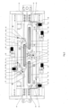
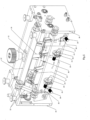
- an ink-jet digital printing machine 1 for printing the outer surface of containers 5 with a longitudinal axis C, particularly containers 5 with rotational symmetry around the longitudinal axis C.
- Containers 5 particularly have a cylindrical outer surface where a graphic pattern is to be printed.
- Containers 5 can be for various purposes, e.g. food cans or cans for deodorants, detergents, etc.
- the printing machine 1 comprises a printing unit 3 and a turntable 2 rotatable around an axis L and supporting a plurality of support mandrels 6 of the containers 5.
- Mandrels 6 are distributed on turntable 2 at constant angular pitch.
- Turntable 2 preferably has a vertical axis of rotation L.
- Mandrels 6 are rotatable on their own axis M and rigidly support in rotation a corresponding container 5 each.
- Mandrels 6 have the axis M oriented radially with respect to the rotational axis L of turntable 2.
- Printing unit 3 comprises a plurality of printing stations 4 that run longitudinally and are each equipped with one or preferably several printheads 8.
- the plurality of printing stations 4 includes printing stations with different coloured inks and at least one printing station with a transparent surface finishing material.
- Printheads 8 have a main lying plane S which, in the case of a substantially parallelepiped shape, corresponds to the centre plane parallel to the two lateral longitudinal surfaces, and a longitudinal axis P.
- the lower longitudinal surface is equipped with one or more parallel longitudinal rows of firing nozzles.
- Turnable 2 is configured to transport and station each mandrel 6 sequentially at printing station 4 where mandrel 6 can rotate on its axis M during printing.
- the mandrel 6 stationed at a printing station 4 has its axis M parallel to and equidistant from the longitudinal axis P of the printheads 8.
- the digital printing machine 1 has a programmable electronic controller, not shown in the figures, for controlling and commanding the printing mode of the graphic pattern(s) to be printed on the cylindrical outer surface of the containers 5.
- the programmable electronic controller includes at least one programme for printing a graphic pattern that can also have a variable thickness.
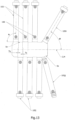
- such a printing program envisages executing in sequence, at the same printing station 4, a first part A, B, C, D, E, F, G of the graphic pattern during a first rotation of 360° of the mandrel 6 on its axis M, and at least a second part A', B', C', D', E' of the graphic pattern during a second rotation of a further 360° of the mandrel 6 on its axis M.
- the second part A', B', C', D', E' of the graphic pattern overlaps with the first part A, B, C, D, E, F, G of the graphic pattern.
- the thickness of the graphic pattern locally by selectively overlapping the second part A', B', C', D', E' of the graphic pattern with a single portion of the first part A, B, C, D, E, F, G of the graphic pattern.
- the portion of the first part A, B, C, D, E, F, G of the graphic pattern includes spatially separated areas
- the second part A', B', C', D', E' of the graphic pattern reproduces and matches these spatially separated areas.
- the graphic pattern printing program provides for printing on the cylindrical outer surface of a container 5 of at least one third part A", B", E" of the graphic pattern during a third 360° rotation of the mandrel 6 on its axis M, wherein the third part A", B", E" of the graphic pattern selectively overlaps, reproduces and matches a portion A', B', E' of the second part A', B', C', D', E' of the graphic pattern.
- the above mentioned graphic pattern printing program can be executed entirely by a single printing station 4.
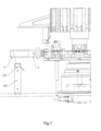
- Printing machine 1 may comprise, as shown, a pretreatment device 102 positioned in a pretreatment station 103.
- the pretreatment device 102 comprises a frame supporting plasma emission means for irradiating the outer surface of the container 5.
- Turnable 2 is configured for transporting and stationing mandrel 6 at pretreatment station 103 before transporting and stationing mandrel 6 at the printing stations.
- Turnable 2 is more precisely configured to transport and station mandrel 6 at an exposure position where the outer surface of container 5 is exposed to plasma.
- mandrel 6 In the exposure position, mandrel 6 can be rotated around its axis M for progressive plasma exposure of the outer surface of container 5.
- Plasma emitters can be modular in design.
- the emission means may comprise first plasma emission modules 105i, 105ii arranged at a first angular position about the axis of mandrel 6 stationed at the exposure position.
- the first 105i, 105ii modules are aligned to radiate an axial sector of the outer surface of container 5.
- the first 105i, 105ii emission modules radiate adjacent and partially overlapping zones of the axial sector of the outer surface of container 5.
- the frame individually supports the first 105i, 105ii modules, which can be removed and repositioned independently of each other as desired.
- Device 102 provides means of varying the direction of emission of the first modules 105i, 105ii.
- the means of varying the direction of emission include hinging pins 106 with which the first modules 105i, 105ii are hinged to the frame.
- Hinging pins 106 are parallel to each other and orthogonal to the axis M of mandrel 6 when stationary in the exposure position.
- the first modules 105i, 105ii can be locked, by means of special locking means not shown, in a range of angular positions around the respective hinging pins 106.
- each of the first emission modules 105i, 105ii can be set so that the angle of incidence ⁇ of the plasma is substantially orthogonal to the corresponding radiated zone of the axial sector of the outer surface of the container 5.
- the first modules 105i, 105ii will have emission surfaces with the same orientation; if, however, areas of the axial sector of the outer surface of the container 5 exposed to the plasma have different layouts, then correspondingly, the first modules 105i, 105ii will also have emission surfaces with different orientations in order to maintain the substantial orthogonality of the plasma incidence angle.
- the radiated axial sector of the outer surface of container 5 comprises a first cylindrical sector zone 5a and a second truncated conical sector zone 5b converging towards the C axis of container 5.
- the first 105i modules radiating the first cylindrical sector zone 5a have an emission surface with the same orientation, while the first 105ii module radiating the second truncated cone sector zone 5b has an emission surface with an orientation different from that of all the other first 105i modules.
- the axial sector of the external surface of the container 5 comprises a first cylindrical sector zone 5a, a second truncated conical sector zone 5b converging towards the C axis of the container 5, a third truncated conical sector zone 5c diverging from the C axis of the container 5, a fourth cylindrical sector zone 5d and a fifth truncated conical sector zone 5e converging towards the C axis of the container.
- the first 105i modules radiating the first cylindrical sector zone 5a and the third cylindrical sector zone 5d present emission surfaces with the same orientation, while the first 105ii modules radiating the various truncated cone sector zones 5b, 5c, 5e present emission surfaces with a different orientation.
- the device 102 also provides means for varying the radial distance of the first emission modules 105i, 105ii from the axis of the mandrel 6 when stationary in the exposure position.
- the means of varying the radial distance of the first emission modules 105i, 105ii serve to keep the distance of the first emission modules 105i, 105ii from the outer surface of the container 5 unchanged as the format of the container 5 itself changes.
- Means of varying the radial distance of the first emission modules 105i, 105ii include, for example, a translatable bar 107 of collective support of the first emission modules 105i, 105ii.
- the frame thus supports the moveable bar 107 from which the first modules 105i, 105ii can be removed and repositioned independently of each other at will.
- hinge pins 106 are individually supported by corresponding blocks, which in turn can be adjusted in position in sliding slots provided in the sliding bar 107.
- one or more second 105j, 105jj plasma emission modules are arranged at a second angular position around the axis of mandrel 6 in stationary at the exposure position.
- the first emission modules 105i, 105ii are diametrically opposed to the second emission modules 105j, 105jj with respect to the axis M of the mandrel 6.
- the second modules 105j, 105jj are aligned to irradiate an axial sector of the outer surface of container 5 diametrically opposite to that irradiated by the first emission modules 105i, 105ii.
- the frame individually supports the second modules 105j, 105jj which can be removed and repositioned independently of each other as desired.
- the device 102 also provides for the second modules 105j, 105jj means of varying the direction of emission similar to those provided for the first modules 105i, 105ii, in particular pins 106 with which the second modules 105j, 105jj are hinged to the frame.
- the device 102 also provides for the second modules 105j, 105jj means of varying their radial distance from the axis of the mandrel 6 when stationary in the exposure position similar to those provided for the first modules 105i, 105ii, in particular a translatable bar 107 for collectively supporting the second emission modules 105j, 105jj.
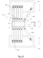
- Figure 13 shows a variant in which the consecutive plasma emission modules 105i, 105j in the direction of the axis M of mandrel 6 have an overlapping section Ts in the direction of the axis M of mandrel 6.
- consecutive modules 105i, 105j in the direction of the axis M of mandrel 6 are on diametrically opposite sides of mandrel 6, but in solutions not shown they can be positioned on the same side of mandrel 6.
- the pretreatment station 103 and the printing stations 4 are positioned along the circular trajectory of the mandrels 6 above the turntable 2 at a defined angular distance pitch around the rotary axis L of the turntable 2, in particular equal to or a multiple of the angular distance pitch of the mandrels 6.
- the digital printing machine 1 provides servo drives for bidirectional linear movement of the plasma emitting means and respectively the printheads 8 of each printing station 4 in a direction parallel to the rotation axis L of the turntable 2.
- the servo drive for the bidirectional linear movement of the plasma emitter means in particular can synchronously drive the bars 107.
- the printing machine 1 also includes a station 100 for detecting the eccentricity profile of the containers 5 positioned upstream of the pretreatment station 102.
- Detection station 100 includes distance sensor means of the containers locked on their mandrels 6 rotating on themselves.
- Detection station 100 also includes an actuator controller for the servo drives in pretreatment station 102 and each printing station 4.
- Detection means 101 comprises one or more non-contact distance sensors, e.g. optical sensors.
- the distance sensors 101 are mounted in a fixed position in the detecting station 100 and are oriented orthogonally to the axis M of the mandrel 6.
- sensors 101 acquire an eccentricity profile of container 5 clamped on mandrel 6.
- the sensors means detect, during the rotation of container 5, its eccentricity by measuring the mutual distance, acquiring a series of points along the outer perimeter profile of container 5.
- Plasma emitter modules and printheads 8 of successive printing stations are moved sequentially according to the same time law while stationed in the same container 5.
- the container 5, once clamped by the mandrel 6, retains its eccentricity and angular position throughout its stay inside the press 1.
- Machine 1 has an initial setup of the plasma emission means and printheads 8 of printing station 4.
- the machine 1 provides for an initial setting of the initial distance of the emission modules from the axis M of the mandrel 6 and an initial setting of the initial distance d between the axis M of the mandrel 6 and the printheads 8 of the printing stations 4 and the orientation of the main laying planes S of the printheads 8.
- the initial setting depends on the format of the containers 5 to be printed.
- the printheads 8 are tilted in such a way that the axis M of the mandrel 6 stationed at print station 4 belongs to the centre plane S of the printheads 8.
- the longitudinal dimension of the printing station 4 must be such that it fits the axial length of the cylindrical printing substrates 5.
- printing stations 4 have several printheads 8, these must have an overlapping F section in the direction of their longitudinal axis P.
- the adjacent printheads 8 In order to ensure the partial overlap and at the same time the required inclination of their main plane of layering S, the adjacent printheads 8 have an offset angle ⁇ of their main plane of layering S with respect to the M axis of the mandrel 6.
- Printing station 4 features a 30, 36 frame supporting the two rows of printheads 8.
- Each order of printheads 8 is supported by a corresponding support structure 13, 23, 31.
- Each support structure 13, 23, 31 comprises a longitudinal plate 13 and, for each printhead 8, an angular support 31a, 31b in turn supporting a cradle 23 for printhead 8.
- Each angular support 31a, 31b is independently supported by the longitudinal plate 13 in a linearly adjustable position along the longitudinal plate 13 itself.
- Each angular support 31a, 31b in turn supports the cradle 23, and the printhead 8 attached to it, in an angularly adjustable position around a pin 32.
- Each angular support 31a, 31b has a base 31a and a shoulder 31b.
- the cradle 23 more precisely is fixed to a base 33 resting against the base 31a of the angular support 31a, 31b.
- Means of setting printhead orientation 8 include a toggle system 9.
- the toggle system 9 can be operated to force a coordinated rotation of the two rows of printheads 8 around a respective fulcrum 10.
- the corresponding fulcrum 10 is positioned at the lower end 11 of the printheads 8 and defines a rotation axis Q parallel to the M axis of the mandrel 6.
- end blocks 36 of the longitudinal plates 13 are engaged.
- end blocks 36 have on their perimeter edge special engagement seats 36 conjugated to fulcrums 10.
- the toggle system 9 has symmetrical connecting rods 12 each of which has its lower end hinged to the longitudinal plate 13 of a corresponding support structure 13, 23, 31a, 31b.
- each connecting rod 12 is operatively connected to a nut 15 engaged to slide along a screw 16 having a vertical axis V that intercepts the axis M of the mandrel 6.
- a longitudinal bar 37 is attached centrally to the nut 15, which has the connecting rods 12 hinged at the opposite ends.
- the screw 16 is supported in a special housing 19 fixed to a longitudinal bar 36 of the frame 30, 36.
- the screw 16 can rotate on itself without translating to drag the mother screw 15 upwards to drive the toggle 9.
- Elastic thrust means are provided to maintain the rotation of the two rows of printheads 8 around their respective fulcrums 10 when the toggle 9 is operated.
- the elastic thrust means comprise symmetrical springs 17 configured and arranged to exert thrust in an oblique direction from top to bottom at the lower hinges of the connecting rods 12.
- Each print station 4 also includes means of fine tuning the mutual position of the printheads 8.
- Fine tuning means include first fine tuning means of overlap F between printheads 8.
- the first means of fine tuning comprise, for each printhead 8, a micrometer screw 20 counteracted by a spring 21 to reset the thread clearance of the micrometer screw 20.
- the micrometer screw 20 is supported in a housing 22 fixed to the longitudinal plate 13 and engages a threaded hole 24 in a flange 25 fixed to the base 31a of the angular support 31a, 31b.
- the angular support 31a, 31b and with it the cradle 23 housing the printhead 8 are moved along the longitudinal plate 13 by operating the micrometer screw 20.
- Fine tuning means also include second fine tuning means of mutual alignment between the longitudinal P axes of the printheads 8.
- the second means of fine tuning comprise, for each printhead 8, a micrometer screw 26 counteracted by a spring 40 resetting the thread clearance of the micrometer screw 26.
- the micrometer screw 26 is supported in a housing 38 fixed to the base 31a of the angular support 31a, 31b and engages a threaded hole 39 in the base 33 of the cradle 23.
- the micrometer screw 26 rotates the cradle 23 around the pin 32 and the rotation of the cradle 23 is counteracted by a spring 41 supported by the shoulder 31b of the angular support 31a, 31b and resting against the cradle 23.
- the spring 41 slides over the cradle 23 allowing the latter to rotate but remains under tension so as to block the angle of rotation achieved by the cradle 23 following the operation of the micrometer screw 26.
- Each printing station 4 is set up to dispense ink of only one colour.
- the printing process takes place as follows.
- first and second plasma emission modules are selected at the pretreatment station 103, their initial linear position is set, for example by adjusting the initial position of the bars 107, and the angle of the emission modules around the pins 106 is set.
- the linear and angular position of printheads 8 is also set at print station 4.
- the toggle 9 is operated to reorient the positioning planes S of the printheads 8 in such a way that the printing can substantially take place with the condition that the container axis 5 belongs to the main positioning plane S of the printheads 8.
- the printheads 8 of each printing station 4 are also set in register by means of the micrometer screws 20, 26, which adjust the overlapping section F between the printheads 8 and respectively the alignment of their longitudinal axis P in the direction parallel to the axis M of the mandrel 6.
- the overlapping section F must be such that it overlaps one or more of the intended firing nozzles in adjacent printheads 8.
- turntable 2 is operated, whose mandrels 6 are supplied with containers 5 from a loader not shown.
- the turntable 2 is rotary driven in steps, and at each step it sequentially positions each container 5 first below the detecting station 100, then below the pretreatment station 103, and finally below the subsequent printing stations 4.
- mandrels 6 are rotated in their axis M.
- Each printing station 4 is dedicated to the application of a single ink of a different colour from that used in the other print stations 4.
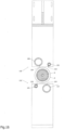
- Figures 14 to 16 show a container cooling station 5 positioned immediately downstream of the plasma station.
- the cooling station comprises at least one cooling module 120 including a cooling compressed air emission tube 121 and a heated air suction tube 122.
- Mandrel 6 is stationed at the cooling station with the axis M parallel to the axis of the emission tube 121 and the axis of the suction tube 122.
- Tubes 121, 122 are configured one for radial air emission and the other for radial air intake.
- the emission tube 121 has emission holes 123 distributed at least along most of the length of the emission tube 121, while the suction tube 122 has a suction slot 124 extending at least along most of the length of the suction tube 122.
- Compressed air is delivered by the emission tube 121 in the direction towards the container 5 and the air stream heated by contact with the surface of the container 5 is sucked in by the suction tube 122.
- the emission tube 121 and the suction tube 122 are connected with appropriate air distribution and smoke suction respectively.
- the cooling station is able to reduce the container surface temperature 5 to an optimum value for inkjet printing.
- the materials used, as well as the dimensions, can be any according to requirements and the state of the art.
Landscapes
- Engineering & Computer Science (AREA)
- Manufacturing & Machinery (AREA)
- Ink Jet (AREA)
- Coating Apparatus (AREA)
Applications Claiming Priority (1)
| Application Number | Priority Date | Filing Date | Title |
|---|---|---|---|
| IT202300003507 | 2023-02-27 |
Publications (2)
| Publication Number | Publication Date |
|---|---|
| EP4420885A1 true EP4420885A1 (de) | 2024-08-28 |
| EP4420885B1 EP4420885B1 (de) | 2026-04-01 |
Family
ID=86329295
Family Applications (1)
| Application Number | Title | Priority Date | Filing Date |
|---|---|---|---|
| EP24156275.0A Active EP4420885B1 (de) | 2023-02-27 | 2024-02-07 | Digitale tintenstrahldruckmaschine und entsprechendes verfahren |
Country Status (1)
| Country | Link |
|---|---|
| EP (1) | EP4420885B1 (de) |
Citations (3)
| Publication number | Priority date | Publication date | Assignee | Title |
|---|---|---|---|---|
| US20050087083A1 (en) * | 2003-06-23 | 2005-04-28 | Francois Dumenil | Machine for printing on articles |
| US20220379647A1 (en) * | 2021-05-28 | 2022-12-01 | Krones Ag | Method for producing a relief-like printed image on containers |
| IT202100014864A1 (it) * | 2021-06-08 | 2022-12-08 | Quantix Digital S R L | Dispositivo di pretrattamento e macchina da stampa digitale a getto di inchiostro che include tale dispositivo di pretrattamento |
-
2024
- 2024-02-07 EP EP24156275.0A patent/EP4420885B1/de active Active
Patent Citations (3)
| Publication number | Priority date | Publication date | Assignee | Title |
|---|---|---|---|---|
| US20050087083A1 (en) * | 2003-06-23 | 2005-04-28 | Francois Dumenil | Machine for printing on articles |
| US20220379647A1 (en) * | 2021-05-28 | 2022-12-01 | Krones Ag | Method for producing a relief-like printed image on containers |
| IT202100014864A1 (it) * | 2021-06-08 | 2022-12-08 | Quantix Digital S R L | Dispositivo di pretrattamento e macchina da stampa digitale a getto di inchiostro che include tale dispositivo di pretrattamento |
Also Published As
| Publication number | Publication date |
|---|---|
| EP4420885B1 (de) | 2026-04-01 |
Similar Documents
| Publication | Publication Date | Title |
|---|---|---|
| US20220080654A1 (en) | Print device | |
| EP2492104B1 (de) | Gerät und Verfahren zum Bedrucken zylindrischer oder konischer Oberflächen | |
| JP3228295B2 (ja) | 缶の間隔と速度を減少させる装置 | |
| US11312158B1 (en) | Method for partial curing of printed images on transparent and semi-transparent media | |
| JP2019093704A (ja) | 回転テーブルデジタル印刷機及び印刷ユニット | |
| US6948425B2 (en) | Machine for printing on articles | |
| EP4420885B1 (de) | Digitale tintenstrahldruckmaschine und entsprechendes verfahren | |
| CN117255748B (zh) | 喷墨数字印刷机 | |
| EP3112175B1 (de) | Verfahren und vorrichtung zum digitalen drucken auf artikeln | |
| CN117425570B (zh) | 预处理设备和包括所述预处理设备的喷墨数字印刷机 | |
| CN117098669B (zh) | 用于在圆柱形基底上进行打印的数字喷墨打印机 | |
| EP4100258B1 (de) | Verfahren zur partiellen härtung von gedruckten bildern auf transparenten und halbtransparenten medien | |
| JP5775733B2 (ja) | 画像形成装置、および、画像が形成された缶体の製造方法 | |
| EP3335878B1 (de) | Druckmaschine | |
| CN109624514B (zh) | 用于印刷多个物体的机器 | |
| JP7507456B2 (ja) | インクジェットラベルプリンターシステム | |
| CN121038967A (zh) | 用于在封盖上进行印刷的喷墨数字印刷机 |
Legal Events
| Date | Code | Title | Description |
|---|---|---|---|
| PUAI | Public reference made under article 153(3) epc to a published international application that has entered the european phase |
Free format text: ORIGINAL CODE: 0009012 |
|
| STAA | Information on the status of an ep patent application or granted ep patent |
Free format text: STATUS: THE APPLICATION HAS BEEN PUBLISHED |
|
| AK | Designated contracting states |
Kind code of ref document: A1 Designated state(s): AL AT BE BG CH CY CZ DE DK EE ES FI FR GB GR HR HU IE IS IT LI LT LU LV MC ME MK MT NL NO PL PT RO RS SE SI SK SM TR |
|
| STAA | Information on the status of an ep patent application or granted ep patent |
Free format text: STATUS: REQUEST FOR EXAMINATION WAS MADE |
|
| 17P | Request for examination filed |
Effective date: 20250121 |
|
| GRAP | Despatch of communication of intention to grant a patent |
Free format text: ORIGINAL CODE: EPIDOSNIGR1 |
|
| STAA | Information on the status of an ep patent application or granted ep patent |
Free format text: STATUS: GRANT OF PATENT IS INTENDED |
|
| INTG | Intention to grant announced |
Effective date: 20250904 |
|
| GRAS | Grant fee paid |
Free format text: ORIGINAL CODE: EPIDOSNIGR3 |
|
| GRAA | (expected) grant |
Free format text: ORIGINAL CODE: 0009210 |
|
| STAA | Information on the status of an ep patent application or granted ep patent |
Free format text: STATUS: THE PATENT HAS BEEN GRANTED |
|
| AK | Designated contracting states |
Kind code of ref document: B1 Designated state(s): AL AT BE BG CH CY CZ DE DK EE ES FI FR GB GR HR HU IE IS IT LI LT LU LV MC ME MK MT NL NO PL PT RO RS SE SI SK SM TR |
|
| REG | Reference to a national code |
Ref country code: CH Ref legal event code: F10 Free format text: ST27 STATUS EVENT CODE: U-0-0-F10-F00 (AS PROVIDED BY THE NATIONAL OFFICE) Effective date: 20260401 Ref country code: GB Ref legal event code: FG4D |
|
| REG | Reference to a national code |
Ref country code: DE Ref legal event code: R096 Ref document number: 602024003509 Country of ref document: DE |
|
| REG | Reference to a national code |
Ref country code: IE Ref legal event code: FG4D |