EP4420899A2 - Reifen - Google Patents
Reifen Download PDFInfo
- Publication number
- EP4420899A2 EP4420899A2 EP24169333.2A EP24169333A EP4420899A2 EP 4420899 A2 EP4420899 A2 EP 4420899A2 EP 24169333 A EP24169333 A EP 24169333A EP 4420899 A2 EP4420899 A2 EP 4420899A2
- Authority
- EP
- European Patent Office
- Prior art keywords
- conductive
- tire radial
- tire
- radial direction
- carcass
- Prior art date
- Legal status (The legal status is an assumption and is not a legal conclusion. Google has not performed a legal analysis and makes no representation as to the accuracy of the status listed.)
- Granted
Links
Images

Classifications
-
- B—PERFORMING OPERATIONS; TRANSPORTING
- B60—VEHICLES IN GENERAL
- B60C—VEHICLE TYRES; TYRE INFLATION; TYRE CHANGING; CONNECTING VALVES TO INFLATABLE ELASTIC BODIES IN GENERAL; DEVICES OR ARRANGEMENTS RELATED TO TYRES
- B60C9/00—Reinforcements or ply arrangement of pneumatic tyres
- B60C9/005—Reinforcements made of different materials, e.g. hybrid or composite cords
-
- B—PERFORMING OPERATIONS; TRANSPORTING
- B60—VEHICLES IN GENERAL
- B60C—VEHICLE TYRES; TYRE INFLATION; TYRE CHANGING; CONNECTING VALVES TO INFLATABLE ELASTIC BODIES IN GENERAL; DEVICES OR ARRANGEMENTS RELATED TO TYRES
- B60C19/00—Tyre parts or constructions not otherwise provided for
- B60C19/08—Electric-charge-dissipating arrangements
- B60C19/086—Electric-charge-dissipating arrangements using conductive sidewalls
-
- B—PERFORMING OPERATIONS; TRANSPORTING
- B60—VEHICLES IN GENERAL
- B60C—VEHICLE TYRES; TYRE INFLATION; TYRE CHANGING; CONNECTING VALVES TO INFLATABLE ELASTIC BODIES IN GENERAL; DEVICES OR ARRANGEMENTS RELATED TO TYRES
- B60C19/00—Tyre parts or constructions not otherwise provided for
- B60C19/08—Electric-charge-dissipating arrangements
-
- B—PERFORMING OPERATIONS; TRANSPORTING
- B60—VEHICLES IN GENERAL
- B60C—VEHICLE TYRES; TYRE INFLATION; TYRE CHANGING; CONNECTING VALVES TO INFLATABLE ELASTIC BODIES IN GENERAL; DEVICES OR ARRANGEMENTS RELATED TO TYRES
- B60C19/00—Tyre parts or constructions not otherwise provided for
- B60C19/08—Electric-charge-dissipating arrangements
- B60C19/082—Electric-charge-dissipating arrangements comprising a conductive tread insert
-
- B—PERFORMING OPERATIONS; TRANSPORTING
- B60—VEHICLES IN GENERAL
- B60C—VEHICLE TYRES; TYRE INFLATION; TYRE CHANGING; CONNECTING VALVES TO INFLATABLE ELASTIC BODIES IN GENERAL; DEVICES OR ARRANGEMENTS RELATED TO TYRES
- B60C13/00—Tyre sidewalls; Protecting, decorating, marking, or the like, thereof
-
- B—PERFORMING OPERATIONS; TRANSPORTING
- B60—VEHICLES IN GENERAL
- B60C—VEHICLE TYRES; TYRE INFLATION; TYRE CHANGING; CONNECTING VALVES TO INFLATABLE ELASTIC BODIES IN GENERAL; DEVICES OR ARRANGEMENTS RELATED TO TYRES
- B60C19/00—Tyre parts or constructions not otherwise provided for
- B60C19/08—Electric-charge-dissipating arrangements
- B60C19/088—Electric-charge-dissipating arrangements using conductive beads
-
- B—PERFORMING OPERATIONS; TRANSPORTING
- B60—VEHICLES IN GENERAL
- B60C—VEHICLE TYRES; TYRE INFLATION; TYRE CHANGING; CONNECTING VALVES TO INFLATABLE ELASTIC BODIES IN GENERAL; DEVICES OR ARRANGEMENTS RELATED TO TYRES
- B60C9/00—Reinforcements or ply arrangement of pneumatic tyres
- B60C9/18—Structure or arrangement of belts or breakers, crown-reinforcing or cushioning layers
- B60C2009/1828—Structure or arrangement of belts or breakers, crown-reinforcing or cushioning layers characterised by special physical properties of the belt ply
-
- B—PERFORMING OPERATIONS; TRANSPORTING
- B60—VEHICLES IN GENERAL
- B60C—VEHICLE TYRES; TYRE INFLATION; TYRE CHANGING; CONNECTING VALVES TO INFLATABLE ELASTIC BODIES IN GENERAL; DEVICES OR ARRANGEMENTS RELATED TO TYRES
- B60C15/00—Tyre beads, e.g. ply turn-up or overlap
- B60C15/06—Flipper strips, fillers, or chafing strips and reinforcing layers for the construction of the bead
- B60C2015/0614—Flipper strips, fillers, or chafing strips and reinforcing layers for the construction of the bead characterised by features of the chafer or clinch portion, i.e. the part of the bead contacting the rim
-
- Y—GENERAL TAGGING OF NEW TECHNOLOGICAL DEVELOPMENTS; GENERAL TAGGING OF CROSS-SECTIONAL TECHNOLOGIES SPANNING OVER SEVERAL SECTIONS OF THE IPC; TECHNICAL SUBJECTS COVERED BY FORMER USPC CROSS-REFERENCE ART COLLECTIONS [XRACs] AND DIGESTS
- Y02—TECHNOLOGIES OR APPLICATIONS FOR MITIGATION OR ADAPTATION AGAINST CLIMATE CHANGE
- Y02T—CLIMATE CHANGE MITIGATION TECHNOLOGIES RELATED TO TRANSPORTATION
- Y02T10/00—Road transport of goods or passengers
- Y02T10/80—Technologies aiming to reduce greenhouse gasses emissions common to all road transportation technologies
- Y02T10/86—Optimisation of rolling resistance, e.g. weight reduction
Definitions
- This disclosure relates to a tire.
- a tire comprising a carcass consisting of one or more carcass ply is known, as described in Patent Document 1.
- the gist structure of this disclosure is as follows.
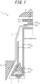
- Figure 1 is a schematic diagram of a tire structure of a tire according to the first embodiment of this disclosure.
- This tire 1 is a pneumatic tire in this example.
- the tire 1 comprises a pair of bead portions 2, a carcass 3, a reinforcement member disposed on the outer side in the tire radial direction of the carcass 3, and a tread portion 5.
- the pair of bead cores 2a are embedded in a pair of bead portions 2, and bead fillers 2b are disposed on the outer side in the tire radial direction of the bead cores 2a.
- the cross-sectional shape and material of the bead cores 2a are not limited, and can be of any configuration normally used in tires.
- the bead fillers 2b can have an abbreviated triangular cross-sectional shape, but the cross-sectional shape of the bead fillers 2b is not limited to this example, nor is its material.
- the carcass 3 comprises one or more carcass plies, each of which consists of a carcass body portion 3a straddling toroidally over the pair of bead cores and a carcass turn-up portions 3b extending from the carcass body portion 3a and folded back around the bead cores 2a.
- the carcass ply is made of organic fibers coated with rubber, and the coating rubber has a low loss tangent. This reduces the rolling resistance of the tire.
- the term "loss tangent" refers to the ratio (E'7E') of the dynamic loss modulus E" value to the dynamic storage modulus E' value obtained on a specimen of vulcanized rubber with a thickness of 2 mm, a width of 5 mm, and a length of 20 mm, at a temperature of 60°C, a frequency of 52 Hz, an initial strain of 2%, and a dynamic strain of 1%, using a dynamic tensile viscoelasticity measuring device.
- the carcass ply is non-conductive (i.e., it does not function sufficiently as a conductive path for static electricity inside the tire to escape to the road surface).
- rubber chafers (gum chafers) 6 are disposed on the outer side in the tire width direction of the bead fillers 2b.
- the rubber chaffers 6 cover the carcass turn-up portions 3b from the outer side in the tire width direction.
- the rubber chafers 6 are conductive.
- the rubber chafers 6 are disposed on at least a portion of the bead portions 2 in contact with the rim.
- canvas chafers 7 are disposed around the bead cores 2a.
- the canvas chafers 7 cover the inner side in the tire radial direction of the bead cores 2a and both sides in the tire width direction of the bead cores 2a.
- the canvas chafers 7 are conductive.
- the canvas chafers 7 made up of a textile and rubber impregnated with the textile.
- the fabric consists of warp and weft yarns, and the warp and weft yarns are made of organic fibers.
- squeegee rubbers 8 are disposed on the inner side in the tire radial direction of the bead core 2a (in the illustrated example, on the inner side in the tire radial direction of the carcass turn-up portion 3b, and on the inner side in the tire radial direction of the canvas chafer 7). This prevents contact between the carcass ply and the canvas chafers 7, thereby preventing failure due to rubbing.
- the squeegee rubbers 8 are non-conductive.
- a reinforcement member comprising one or more reinforcement layers is disposed on the outer side in the tire radial direction of the crown portion of the carcass 3.
- the reinforcement member comprises a belt 4 consisting of two belt layers 4a and 4b, a belt reinforcement layer 9 disposed on the outer side in the tire radial direction of the belt 4, and a reinforcement rubber (tread under cushion) 10 disposed on the outer side in the tire radial direction of the belt reinforcement layer 9.
- the belt layers 4a and 4b are composed of plies in which belt cords are coated with rubber and are inclined with respect to the tire circumferential direction (for example, at an inclination angle of 30 to 60 degrees) so as to intersect with each other between the layers.
- the belt cords can be, for example, steel cords.
- the belt layers 4a and 4b are conductive. Although the number of belt layers is two in this example, it may be one or more layers, and the inclination angle with respect to the tire circumferential direction is not limited to the above range.
- the belt reinforcement layer 9 is composed of a ply in which cords are coated with rubber and extend in the tire circumferential direction.
- the belt layer 9 is a pair of layers covering only the end in the tire width direction of the belt 4.
- the cords can be, for example, steel cords.
- the belt reinforcement layer 9 is non-conductive.
- the belt reinforcement layer 9 is one layer, but it can be two or more layers.
- an additional so-called cap layer which covers the entire belt width can be disposed between the belt 4 and the pair of layers in the tire radial direction.
- the cap layer can be disposed.
- the cap layer it shall be conductive.
- Each reinforcement layer shall be conductive or non-conductive so as to form a conductive path, and each reinforcement layer is disposed only at a portion in the tire width direction, so that the region where the reinforcement layer is not disposed becomes a conductive path.
- the tire 1 does not necessarily to have a belt reinforcement layer 9.
- the belt reinforcement layer 9 can be disposed on the inner side in the tire radial direction than the belt 4.
- the reinforcement rubber (tread under cushion) 10 is disposed between the tread portion 5 and the belt reinforcement layer 9 in the tire radial direction in the illustrated example.
- the tread under cushion 10 is conductive.
- the tread portion 5 is less conductive.
- the tread portion 5 can be, for example, a so-called cap-and-base construction, in which the cap rubber is disposed on the outer side in the tire radial direction of the base rubber.
- a portion of the tread portion 5 in the tire width direction consists of antenna rubber 5a.
- the antenna rubber 5a is conductive.
- the antenna rubber 5a can be arranged continuously or intermittently in the tire circumferential direction.
- the tire 1 of this embodiment further comprises a conductive member 11.
- the conductive member 11 is a conductive fiber member.
- the conductive fiber member can be, for example, made of cotton fibers and pieces of SUS blended and twisted together. This allows the fiber to be lightweight and conductive. For weight reduction, the fiber preferably consists of only one strand.
- the inner end in the tire radial direction of the conductive member 11 is located at a tire radial position of an outer end in the tire radial direction of the rubber chafer 6 or in a tire radial region inner in the tire radial direction than the outer end in the tire radial direction of the rubber chafer 6, as illustrated.
- the conductive member 11 extends from the inner end in the tire radial direction thereof outwardly in the tire radial direction to at least a position of any of the reinforcement layers which is conductive among the one or more reinforcement layers.
- the tire 1 comprises a pair of conductive members 11, one in each half portion in the tire width direction bounded by the tire equatorial plane, and thus each conductive member 11 has an outer end in the tire radial direction.
- the outer ends in the tire radial direction of the conductive members 11 terminate at a position of an end of any of the reinforcement layers which is conductive among the one or more reinforcement layers (in the illustrated example, the belt layer 4a).
- the outer ends in the tire radial direction of the conductive members 11 terminate in a tire radial region between the crown portion of the carcass 3 and the innermost reinforcement layer in the tire radial direction which is conductive (in the illustrated example, belt layer 4a).
- the outer edge in the tire radial direction of the conductive member 11 and the belt 4a are in electrical contact.
- the coating rubber of the carcass ply is made of rubber with low loss tangent as described above, rolling resistance can be reduced and fuel efficiency can be improved.
- the carcass 3 is non-conductive.
- the rubber chafer 6, the belt layers 4a and 4b, the tire widthwise region between the pair of belt reinforcement layers 9, the tread under cushion 10, and the antenna rubber 5a are conductive.
- the inner end in the tire radial direction of the conductive member 11 is located at the tire radial position of the outer end in the tire radial direction of the rubber chafer 6 or in the tire radial region inner in the tire radial direction than the outer end in the tire radial direction of the rubber chafer 6 as illustrated, so that the rubber chafer 6 and the conductive member 11 are in electrical contact.
- the conductive member 11 extends from the inner end in the tire radial direction thereof outwardly in the tire radial direction to at least the position of any of the reinforcement layers which is conductive among the one or more reinforcement layers (in the illustrated example, the outer end in the tire radial direction of the conductive member 11 terminates at the location of the end of the belt layer 4a), so that the conductive member 11 and the belt layer 4a are in electrical contact.
- a conductive path is formed in the order of the rubber chafer 6, the conductive member 11, the belt layer 4a, the belt layer 4b, the tire widthwise region between the pair of belt reinforcement layers 9, the tread under cushion 10, and the antenna rubber 5a, where static electricity can be dissipated.
- This allows static electricity, which is accumulated inside the tire from the vehicle, to be dissipated from the rubber chafer 6 to the belt 4 and from the belt 4 to the road surface, through the above conductive path, as indicated by the arrow in Figure 1 .
- the structure can easily dissipate the static electricity from the vehicle to the road surface.
- the conductive member 11 is a conductive fiber member, the increase in weight due to the addition of the conductive member 11 can be controlled and the increase in rolling resistance can be suppressed.
- the conductive fiber member can be made of cotton fibers and pieces of SUS blended and twisted together, so that to make the conductive member lightweight and conductive.
- the belt layer 4b which is the innermost reinforcement layer in the tire radial direction, and the conductive member 11 are in electrical contact and the conductive member 11 terminates at the end of the belt layer 4b, so that the length of the conductive member 11 can be shortened to further control the weight gain and further reduce the increase in rolling resistance.
- Figure 2 is a schematic diagram of a tire structure of a tire according to the second embodiment of this disclosure.
- the tire 12 of the second embodiment differs from the first embodiment only in the arrangement of the conductive member 13, and the composition of the other members and the material of the conductive member 13 are the same as those in the first embodiment, so the description is omitted.
- the inner end in the tire radial direction of the conductive member 13 is located at a tire radial position of an outer end in the tire radial direction of the rubber chafer 6 or in a tire radial region inner in the tire radial direction than the outer end in the tire radial direction of the rubber chafer 6, as illustrated, and this is the same as in the first embodiment.
- the conductive member 13 extends from the inner end in the tire radial direction thereof outwardly in the tire radial direction to at least a position of any of the reinforcement layers which is conductive among the one or more reinforcement layers, and for a pair of conductive members 13, the outer ends in the tire radial direction of the conductive members 13 terminate at a position of an end of any of the reinforcement layers which is conductive among the one or more reinforcement layers.
- the tire 12 of the second embodiment differs from the first embodiment in that the outer ends in the tire radial direction of the conductive members 13 terminate in a tire radial region between the tread portion 5 and the outermost reinforcement layer in the tire radial direction which is conductive among one or more reinforcement layers (in the illustrated example, the tread under cushion 10).
- the coating rubber of the carcass ply is made of rubber with low loss tangent as described above, rolling resistance can be reduced and fuel efficiency can be improved.
- the carcass 3 is non-conductive.
- the rubber chafer 6, the belt layers 4a and 4b, the tire widthwise region between the pair of belt reinforcement layers 9, the tread under cushion 10, and the antenna rubber 5a are conductive.
- the inner end in the tire radial direction of the conductive member 13 is located at a tire radial position of the outer end in the tire radial direction of the rubber chafer 6 or in a tire radial region inner in the tire radial direction than the outer end in the tire radial direction of the rubber chafer 6 as illustrated, so that the rubber chafer 6 and the conductive member 13 are in electrical contact.
- the conductive member 13 extends from the inner end in the tire radial direction thereof outwardly in the tire radial direction to at least a position of any of the reinforcement layers which is conductive among the one or more reinforcement layers (in the illustrated example, the outer end in the tire radial direction of the conductive member 13 terminates at the location of the end of the tread under cushion 10), so that the conductive member 13 and the tread under cushion 10 are in electrical contact.
- a conductive path is formed in the order of the rubber chafer 6, the conductive member 11, the tread under cushion 10, and the antenna rubber 5a, where static electricity can be dissipated.
- This allows static electricity, which is accumulated inside the tire from the vehicle, to be dissipated through the above conductive path, as indicated by the arrow in Figure 2 .
- the structure can easily dissipate the static electricity from the vehicle to the road surface.
- the conductive member 13 is a conductive fiber member, the increase in weight due to the addition of the conductive member 13 can be controlled and the increase in rolling resistance can be suppressed.
- the conductive fiber member can be made of cotton fibers and pieces of SUS blended and twisted together, so that to make the conductive member lightweight and conductive.
- the tread under cushion 10, which is the outermost reinforcement layer in the tire radial direction, and the conductive member 13 are in electrical contact, so static electricity can be more reliably dissipated to the road surface.
- the length of the conductive member 13 becomes longer as seen in the tire radial direction (when compared to the first embodiment, for example).
- the width in the tire width direction of the tread under cushion 10 is larger than the width in the tire width direction of the maximum width belt layer (belt layer 4b, in this example), and the conductive member 13 is configured to terminate at the position of the end of the tread under cushion 10, thereby shortening the length of the conductive member 13 as seen in the tire width direction, so that the increase in weight can be controlled and the increase in rolling resistance can be suppressed.
- the tire when the tire comprises two or more reinforcement layers, the tire can also be configured so that the outer end in the tire radial direction of the conductive member terminates in a tire radial region between two of the reinforcement layers which are conductive and adjacent to each other in the tire radial direction.
- the coating rubber of the carcass ply is made of a material to reduce the rolling resistance as described above, the structure can easily dissipate static electricity from the vehicle to the road surface.
- the length of the conductive member extending in the tire radial direction is shorter than in the second embodiment, the effect of weight reduction can be achieved, and since the number of members forming the conductive path is less than in the first embodiment, the effect of dissipating static electricity can be obtained more reliably.
- the conductive member can be configured so that one conductive member extends continuously from a tire radial position of the outer end in the tire radial direction of the rubber chafer or a tire radial region inner in the tire radial direction than the outer end in the tire radial direction of the rubber chafer in one half of the tire in the tire width direction to a tire radial position of the outer end in the tire radial direction of the rubber chafer or a tire radial region inner in the tire radial direction than the outer end in the tire radial direction of the rubber chafer in another half of the tire in the tire width direction.
- the conductive member extends throughout any of the reinforcement layers which is conductive among one or more of the reinforcement layers. This configuration also facilitates the dissipation of static electricity from the vehicle to the road surface.
- the inner end in the tire radial direction of the conductive member is in electrical contact with the rubber chafer (i.e., the conductive member is configured such that its inner end in the tire radial direction forms a conductive path with the rubber chafer).
- the conductive member is in electrical contact, at least, with any of the reinforcement layers which is conductive among one or more of the reinforcement layers, from the inner end in the tire radial direction thereof outwardly in the tire radial direction (that is, the conductive member is configured to form a conductive path with the reinforcement layer, which is conductive).
- the tire comprises a pair of conductive members, wherein the outer end in the tire radial direction of the conductive member is in electrical contact with any of the reinforcement layers which is conductive (that is, the conductive member is configured to form a conductive path with the reinforcement layer which is conductive at the outer end in the tire radial direction thereof).
Landscapes
- Engineering & Computer Science (AREA)
- Mechanical Engineering (AREA)
- Tires In General (AREA)
Applications Claiming Priority (3)
| Application Number | Priority Date | Filing Date | Title |
|---|---|---|---|
| JP2021121849A JP2023017521A (ja) | 2021-07-26 | 2021-07-26 | タイヤ |
| EP22849326.8A EP4378715A4 (de) | 2021-07-26 | 2022-07-19 | Reifen |
| PCT/JP2022/028109 WO2023008264A1 (ja) | 2021-07-26 | 2022-07-19 | タイヤ |
Related Parent Applications (2)
| Application Number | Title | Priority Date | Filing Date |
|---|---|---|---|
| EP22849326.8A Division EP4378715A4 (de) | 2021-07-26 | 2022-07-19 | Reifen |
| EP22849326.8A Division-Into EP4378715A4 (de) | 2021-07-26 | 2022-07-19 | Reifen |
Publications (3)
| Publication Number | Publication Date |
|---|---|
| EP4420899A2 true EP4420899A2 (de) | 2024-08-28 |
| EP4420899A3 EP4420899A3 (de) | 2024-09-25 |
| EP4420899B1 EP4420899B1 (de) | 2025-12-24 |
Family
ID=85087614
Family Applications (3)
| Application Number | Title | Priority Date | Filing Date |
|---|---|---|---|
| EP24169333.2A Active EP4420899B1 (de) | 2021-07-26 | 2022-07-19 | Reifen |
| EP25172066.0A Pending EP4566841A3 (de) | 2021-07-26 | 2022-07-19 | Reifen |
| EP22849326.8A Pending EP4378715A4 (de) | 2021-07-26 | 2022-07-19 | Reifen |
Family Applications After (2)
| Application Number | Title | Priority Date | Filing Date |
|---|---|---|---|
| EP25172066.0A Pending EP4566841A3 (de) | 2021-07-26 | 2022-07-19 | Reifen |
| EP22849326.8A Pending EP4378715A4 (de) | 2021-07-26 | 2022-07-19 | Reifen |
Country Status (5)
| Country | Link |
|---|---|
| US (1) | US12420600B2 (de) |
| EP (3) | EP4420899B1 (de) |
| JP (1) | JP2023017521A (de) |
| CN (3) | CN118457099A (de) |
| WO (1) | WO2023008264A1 (de) |
Family Cites Families (16)
| Publication number | Priority date | Publication date | Assignee | Title |
|---|---|---|---|---|
| JPH06127211A (ja) * | 1992-10-13 | 1994-05-10 | Bridgestone Corp | 空気入りラジアルタイヤの組合せ体 |
| JP2004082586A (ja) * | 2002-08-28 | 2004-03-18 | Bridgestone Corp | 空気入りタイヤの製造方法 |
| US7284582B2 (en) * | 2003-10-23 | 2007-10-23 | The Goodyear Tire & Rubber Company | Pneumatic tire with electrically conductive cord extending between a bead portion and a tread portion of the tire |
| DE602005004481T2 (de) * | 2004-11-18 | 2009-01-22 | Société de Technologie Michelin | Elektrisch leitender Gummistreifen |
| FR2937283A1 (fr) * | 2008-10-17 | 2010-04-23 | Michelin Soc Tech | Pneumatique comportant un fil conducteur traversant des nappes de renfort sommet non conductrices de l'electricite, dispositif et procede associe |
| JP5091938B2 (ja) * | 2009-12-15 | 2012-12-05 | 住友ゴム工業株式会社 | 空気入りタイヤ |
| JP2014213747A (ja) * | 2013-04-25 | 2014-11-17 | 東洋ゴム工業株式会社 | 空気入りタイヤ |
| JP2015020499A (ja) | 2013-07-17 | 2015-02-02 | 株式会社ブリヂストン | 空気入りタイヤ |
| WO2016056443A1 (ja) * | 2014-10-06 | 2016-04-14 | 住友ゴム工業株式会社 | ゴム組成物又は空気入りタイヤ |
| JP6354515B2 (ja) * | 2014-10-20 | 2018-07-11 | 横浜ゴム株式会社 | 空気入りタイヤ |
| WO2017122821A1 (ja) * | 2016-01-13 | 2017-07-20 | 株式会社ブリヂストン | 空気入りタイヤ |
| EP3260305B1 (de) * | 2016-06-22 | 2019-03-13 | Sumitomo Rubber Industries, Ltd. | Luftreifen |
| JP2019081401A (ja) * | 2017-10-27 | 2019-05-30 | 株式会社ブリヂストン | 空気入りタイヤ |
| JP7002314B2 (ja) * | 2017-12-13 | 2022-02-10 | 株式会社ブリヂストン | 空気入りタイヤ |
| JP2020040634A (ja) * | 2018-09-13 | 2020-03-19 | 株式会社ブリヂストン | タイヤ |
| JP7161975B2 (ja) | 2019-06-19 | 2022-10-27 | 株式会社ブリヂストン | タイヤ |
-
2021
- 2021-07-26 JP JP2021121849A patent/JP2023017521A/ja active Pending
-
2022
- 2022-07-19 CN CN202410620922.6A patent/CN118457099A/zh active Pending
- 2022-07-19 US US18/564,727 patent/US12420600B2/en active Active
- 2022-07-19 EP EP24169333.2A patent/EP4420899B1/de active Active
- 2022-07-19 CN CN202410620921.1A patent/CN118457098A/zh active Pending
- 2022-07-19 EP EP25172066.0A patent/EP4566841A3/de active Pending
- 2022-07-19 EP EP22849326.8A patent/EP4378715A4/de active Pending
- 2022-07-19 WO PCT/JP2022/028109 patent/WO2023008264A1/ja not_active Ceased
- 2022-07-19 CN CN202280039575.7A patent/CN117412872A/zh active Pending
Also Published As
| Publication number | Publication date |
|---|---|
| EP4420899A3 (de) | 2024-09-25 |
| JP2023017521A (ja) | 2023-02-07 |
| WO2023008264A1 (ja) | 2023-02-02 |
| EP4420899B1 (de) | 2025-12-24 |
| EP4378715A1 (de) | 2024-06-05 |
| CN118457099A (zh) | 2024-08-09 |
| EP4378715A4 (de) | 2025-01-08 |
| US12420600B2 (en) | 2025-09-23 |
| CN118457098A (zh) | 2024-08-09 |
| EP4566841A3 (de) | 2025-08-20 |
| US20240270027A1 (en) | 2024-08-15 |
| CN117412872A (zh) | 2024-01-16 |
| EP4566841A2 (de) | 2025-06-11 |
Similar Documents
| Publication | Publication Date | Title |
|---|---|---|
| US20200331308A1 (en) | Pneumatic tire | |
| US20130056128A1 (en) | Pneumatic tire with conductive bleeder cords | |
| US20110259488A1 (en) | Carcass ply for a pneumatic tire | |
| BR102012021945A2 (pt) | Pneu de aeronave | |
| JP2016088511A (ja) | 三次元部品を備える空気入りタイヤ | |
| BR102013014604A2 (pt) | Um pneu com uma camada de cobertura segmentada | |
| EP2463124A2 (de) | Luftreifen | |
| BRPI1105269A2 (pt) | pneu com um reforço de tecido metálico | |
| US20100018626A1 (en) | Pneumatic tire with a polyketone chipper and/or flipper | |
| EP2423001B1 (de) | Luftreifen | |
| EP4420899A2 (de) | Reifen | |
| US20100065183A1 (en) | Turnup reinforcing structure for pneumatic tires | |
| US20160288574A1 (en) | Crown reinforcement for a pneumatic tire | |
| JP7749370B2 (ja) | タイヤ及びタイヤの製造方法 | |
| JP7733549B2 (ja) | タイヤ | |
| JP7744173B2 (ja) | タイヤ及びタイヤの製造方法 | |
| JP5102064B2 (ja) | 航空機用空気入りタイヤ | |
| US20240227464A1 (en) | Tire, method of manufacturing tire, and raw tire | |
| US10350947B2 (en) | Aircraft tire | |
| US20160167453A1 (en) | Aircraft tire with different modulus ply | |
| CN112477524A (zh) | 重载用充气轮胎 | |
| JPH10147116A (ja) | 重荷重用空気入りラジアルタイヤ | |
| EP3176005A1 (de) | Bidirektionale eingürtelkonstruktion für einen luftreifen | |
| JP5460463B2 (ja) | 空気入りタイヤ | |
| CN118265613A (zh) | 具有带束箍带的车辆充气轮胎 |
Legal Events
| Date | Code | Title | Description |
|---|---|---|---|
| PUAI | Public reference made under article 153(3) epc to a published international application that has entered the european phase |
Free format text: ORIGINAL CODE: 0009012 |
|
| STAA | Information on the status of an ep patent application or granted ep patent |
Free format text: STATUS: REQUEST FOR EXAMINATION WAS MADE |
|
| PUAL | Search report despatched |
Free format text: ORIGINAL CODE: 0009013 |
|
| 17P | Request for examination filed |
Effective date: 20240409 |
|
| AC | Divisional application: reference to earlier application |
Ref document number: 4378715 Country of ref document: EP Kind code of ref document: P |
|
| AK | Designated contracting states |
Kind code of ref document: A2 Designated state(s): AL AT BE BG CH CY CZ DE DK EE ES FI FR GB GR HR HU IE IS IT LI LT LU LV MC MK MT NL NO PL PT RO RS SE SI SK SM TR |
|
| AK | Designated contracting states |
Kind code of ref document: A3 Designated state(s): AL AT BE BG CH CY CZ DE DK EE ES FI FR GB GR HR HU IE IS IT LI LT LU LV MC MK MT NL NO PL PT RO RS SE SI SK SM TR |
|
| RIC1 | Information provided on ipc code assigned before grant |
Ipc: B60C 13/00 20060101ALN20240821BHEP Ipc: B60C 15/06 20060101ALN20240821BHEP Ipc: B60C 9/00 20060101ALI20240821BHEP Ipc: B60C 19/08 20060101AFI20240821BHEP |
|
| GRAP | Despatch of communication of intention to grant a patent |
Free format text: ORIGINAL CODE: EPIDOSNIGR1 |
|
| STAA | Information on the status of an ep patent application or granted ep patent |
Free format text: STATUS: GRANT OF PATENT IS INTENDED |
|
| RIC1 | Information provided on ipc code assigned before grant |
Ipc: B60C 19/08 20060101AFI20250731BHEP Ipc: B60C 9/00 20060101ALI20250731BHEP Ipc: B60C 15/06 20060101ALN20250731BHEP Ipc: B60C 13/00 20060101ALN20250731BHEP Ipc: B60C 9/18 20060101ALN20250731BHEP |
|
| INTG | Intention to grant announced |
Effective date: 20250903 |
|
| GRAS | Grant fee paid |
Free format text: ORIGINAL CODE: EPIDOSNIGR3 |
|
| P01 | Opt-out of the competence of the unified patent court (upc) registered |
Free format text: CASE NUMBER: UPC_APP_9422_4420899/2025 Effective date: 20251009 |
|
| GRAA | (expected) grant |
Free format text: ORIGINAL CODE: 0009210 |
|
| STAA | Information on the status of an ep patent application or granted ep patent |
Free format text: STATUS: THE PATENT HAS BEEN GRANTED |
|
| AC | Divisional application: reference to earlier application |
Ref document number: 4378715 Country of ref document: EP Kind code of ref document: P |
|
| AK | Designated contracting states |
Kind code of ref document: B1 Designated state(s): AL AT BE BG CH CY CZ DE DK EE ES FI FR GB GR HR HU IE IS IT LI LT LU LV MC MK MT NL NO PL PT RO RS SE SI SK SM TR |
|
| REG | Reference to a national code |
Ref country code: CH Ref legal event code: F10 Free format text: ST27 STATUS EVENT CODE: U-0-0-F10-F00 (AS PROVIDED BY THE NATIONAL OFFICE) Effective date: 20251224 Ref country code: GB Ref legal event code: FG4D |
|
| REG | Reference to a national code |
Ref country code: DE Ref legal event code: R096 Ref document number: 602022027664 Country of ref document: DE |
|
| REG | Reference to a national code |
Ref country code: LT Ref legal event code: MG9D |
|
| PG25 | Lapsed in a contracting state [announced via postgrant information from national office to epo] |
Ref country code: NO Free format text: LAPSE BECAUSE OF FAILURE TO SUBMIT A TRANSLATION OF THE DESCRIPTION OR TO PAY THE FEE WITHIN THE PRESCRIBED TIME-LIMIT Effective date: 20260324 |
|
| PG25 | Lapsed in a contracting state [announced via postgrant information from national office to epo] |
Ref country code: FI Free format text: LAPSE BECAUSE OF FAILURE TO SUBMIT A TRANSLATION OF THE DESCRIPTION OR TO PAY THE FEE WITHIN THE PRESCRIBED TIME-LIMIT Effective date: 20251224 Ref country code: HR Free format text: LAPSE BECAUSE OF FAILURE TO SUBMIT A TRANSLATION OF THE DESCRIPTION OR TO PAY THE FEE WITHIN THE PRESCRIBED TIME-LIMIT Effective date: 20251224 |
|
| PG25 | Lapsed in a contracting state [announced via postgrant information from national office to epo] |
Ref country code: RS Free format text: LAPSE BECAUSE OF FAILURE TO SUBMIT A TRANSLATION OF THE DESCRIPTION OR TO PAY THE FEE WITHIN THE PRESCRIBED TIME-LIMIT Effective date: 20260324 |
|
| PG25 | Lapsed in a contracting state [announced via postgrant information from national office to epo] |
Ref country code: LV Free format text: LAPSE BECAUSE OF FAILURE TO SUBMIT A TRANSLATION OF THE DESCRIPTION OR TO PAY THE FEE WITHIN THE PRESCRIBED TIME-LIMIT Effective date: 20251224 |