EP4420901A1 - Essieu à bras oscillants longitudinaux et son procédé de fabrication - Google Patents
Essieu à bras oscillants longitudinaux et son procédé de fabrication Download PDFInfo
- Publication number
- EP4420901A1 EP4420901A1 EP23158522.5A EP23158522A EP4420901A1 EP 4420901 A1 EP4420901 A1 EP 4420901A1 EP 23158522 A EP23158522 A EP 23158522A EP 4420901 A1 EP4420901 A1 EP 4420901A1
- Authority
- EP
- European Patent Office
- Prior art keywords
- axle
- sheet metal
- trailing arm
- axle element
- mounting
- Prior art date
- Legal status (The legal status is an assumption and is not a legal conclusion. Google has not performed a legal analysis and makes no representation as to the accuracy of the status listed.)
- Pending
Links
Images




Classifications
-
- B—PERFORMING OPERATIONS; TRANSPORTING
- B60—VEHICLES IN GENERAL
- B60G—VEHICLE SUSPENSION ARRANGEMENTS
- B60G9/00—Resilient suspensions of a rigid axle or axle housing for two or more wheels
- B60G9/003—Resilient suspensions of a rigid axle or axle housing for two or more wheels the axle being rigidly connected to a trailing guiding device
-
- B—PERFORMING OPERATIONS; TRANSPORTING
- B60—VEHICLES IN GENERAL
- B60B—VEHICLE WHEELS; CASTORS; AXLES FOR WHEELS OR CASTORS; INCREASING WHEEL ADHESION
- B60B35/00—Axle units; Parts thereof ; Arrangements for lubrication of axles
- B60B35/004—Mounting arrangements for axles
- B60B35/006—Mounting arrangements for axles with mounting plates or consoles fitted to axles
- B60B35/007—Mounting arrangements for axles with mounting plates or consoles fitted to axles for mounting suspension elements to axles
-
- B—PERFORMING OPERATIONS; TRANSPORTING
- B60—VEHICLES IN GENERAL
- B60B—VEHICLE WHEELS; CASTORS; AXLES FOR WHEELS OR CASTORS; INCREASING WHEEL ADHESION
- B60B35/00—Axle units; Parts thereof ; Arrangements for lubrication of axles
- B60B35/02—Dead axles, i.e. not transmitting torque
- B60B35/04—Dead axles, i.e. not transmitting torque straight
-
- B—PERFORMING OPERATIONS; TRANSPORTING
- B60—VEHICLES IN GENERAL
- B60B—VEHICLE WHEELS; CASTORS; AXLES FOR WHEELS OR CASTORS; INCREASING WHEEL ADHESION
- B60B35/00—Axle units; Parts thereof ; Arrangements for lubrication of axles
- B60B35/02—Dead axles, i.e. not transmitting torque
- B60B35/08—Dead axles, i.e. not transmitting torque of closed hollow section
-
- B—PERFORMING OPERATIONS; TRANSPORTING
- B60—VEHICLES IN GENERAL
- B60G—VEHICLE SUSPENSION ARRANGEMENTS
- B60G7/00—Pivoted suspension arms; Accessories thereof
- B60G7/001—Suspension arms, e.g. constructional features
-
- B—PERFORMING OPERATIONS; TRANSPORTING
- B60—VEHICLES IN GENERAL
- B60G—VEHICLE SUSPENSION ARRANGEMENTS
- B60G7/00—Pivoted suspension arms; Accessories thereof
- B60G7/008—Attaching arms to unsprung part of vehicle
-
- B—PERFORMING OPERATIONS; TRANSPORTING
- B60—VEHICLES IN GENERAL
- B60G—VEHICLE SUSPENSION ARRANGEMENTS
- B60G2200/00—Indexing codes relating to suspension types
- B60G2200/30—Rigid axle suspensions
- B60G2200/31—Rigid axle suspensions with two trailing arms rigidly connected to the axle
-
- B—PERFORMING OPERATIONS; TRANSPORTING
- B60—VEHICLES IN GENERAL
- B60G—VEHICLE SUSPENSION ARRANGEMENTS
- B60G2202/00—Indexing codes relating to the type of spring, damper or actuator
- B60G2202/10—Type of spring
- B60G2202/15—Fluid spring
- B60G2202/152—Pneumatic spring
-
- B—PERFORMING OPERATIONS; TRANSPORTING
- B60—VEHICLES IN GENERAL
- B60G—VEHICLE SUSPENSION ARRANGEMENTS
- B60G2204/00—Indexing codes related to suspensions per se or to auxiliary parts
- B60G2204/10—Mounting of suspension elements
- B60G2204/14—Mounting of suspension arms
- B60G2204/148—Mounting of suspension arms on the unsprung part of the vehicle, e.g. wheel knuckle or rigid axle
-
- B—PERFORMING OPERATIONS; TRANSPORTING
- B60—VEHICLES IN GENERAL
- B60G—VEHICLE SUSPENSION ARRANGEMENTS
- B60G2204/00—Indexing codes related to suspensions per se or to auxiliary parts
- B60G2204/40—Auxiliary suspension parts; Adjustment of suspensions
- B60G2204/43—Fittings, brackets or knuckles
- B60G2204/4306—Bracket or knuckle for rigid axles, e.g. for clamping
-
- B—PERFORMING OPERATIONS; TRANSPORTING
- B60—VEHICLES IN GENERAL
- B60G—VEHICLE SUSPENSION ARRANGEMENTS
- B60G2206/00—Indexing codes related to the manufacturing of suspensions: constructional features, the materials used, procedures or tools
- B60G2206/01—Constructional features of suspension elements, e.g. arms, dampers, springs
- B60G2206/10—Constructional features of arms
- B60G2206/11—Constructional features of arms the arm being a radius or track or torque or steering rod or stabiliser end link
-
- B—PERFORMING OPERATIONS; TRANSPORTING
- B60—VEHICLES IN GENERAL
- B60G—VEHICLE SUSPENSION ARRANGEMENTS
- B60G2206/00—Indexing codes related to the manufacturing of suspensions: constructional features, the materials used, procedures or tools
- B60G2206/01—Constructional features of suspension elements, e.g. arms, dampers, springs
- B60G2206/10—Constructional features of arms
- B60G2206/16—Constructional features of arms the arm having a U profile and/or made of a plate
-
- B—PERFORMING OPERATIONS; TRANSPORTING
- B60—VEHICLES IN GENERAL
- B60G—VEHICLE SUSPENSION ARRANGEMENTS
- B60G2206/00—Indexing codes related to the manufacturing of suspensions: constructional features, the materials used, procedures or tools
- B60G2206/01—Constructional features of suspension elements, e.g. arms, dampers, springs
- B60G2206/30—Constructional features of rigid axles
- B60G2206/31—Straight axle
-
- B—PERFORMING OPERATIONS; TRANSPORTING
- B60—VEHICLES IN GENERAL
- B60G—VEHICLE SUSPENSION ARRANGEMENTS
- B60G2206/00—Indexing codes related to the manufacturing of suspensions: constructional features, the materials used, procedures or tools
- B60G2206/01—Constructional features of suspension elements, e.g. arms, dampers, springs
- B60G2206/30—Constructional features of rigid axles
- B60G2206/32—Hollow cross section
-
- B—PERFORMING OPERATIONS; TRANSPORTING
- B60—VEHICLES IN GENERAL
- B60G—VEHICLE SUSPENSION ARRANGEMENTS
- B60G2206/00—Indexing codes related to the manufacturing of suspensions: constructional features, the materials used, procedures or tools
- B60G2206/01—Constructional features of suspension elements, e.g. arms, dampers, springs
- B60G2206/70—Materials used in suspensions
- B60G2206/72—Steel
- B60G2206/722—Plates
-
- B—PERFORMING OPERATIONS; TRANSPORTING
- B60—VEHICLES IN GENERAL
- B60G—VEHICLE SUSPENSION ARRANGEMENTS
- B60G2206/00—Indexing codes related to the manufacturing of suspensions: constructional features, the materials used, procedures or tools
- B60G2206/01—Constructional features of suspension elements, e.g. arms, dampers, springs
- B60G2206/80—Manufacturing procedures
- B60G2206/82—Joining
- B60G2206/8201—Joining by welding
-
- B—PERFORMING OPERATIONS; TRANSPORTING
- B60—VEHICLES IN GENERAL
- B60G—VEHICLE SUSPENSION ARRANGEMENTS
- B60G2206/00—Indexing codes related to the manufacturing of suspensions: constructional features, the materials used, procedures or tools
- B60G2206/01—Constructional features of suspension elements, e.g. arms, dampers, springs
- B60G2206/90—Maintenance
- B60G2206/91—Assembly procedures
Definitions
- the invention relates to a trailing arm axle arrangement for a commercial vehicle, in particular a truck, trailer or semi-trailer, with an axle element and a trailing arm for connection to a spring device, wherein the trailing arm is fixed to at least two mounting sections of the axle element that are spaced apart from one another in the longitudinal direction of the axle element.
- the invention further relates to a method for producing such a trailing arm axle arrangement.
- Commercial vehicles are known in various designs, for example in the form of trucks, trailers or semi-trailers. Regardless of their design, commercial vehicles are intended in particular for the transport of goods, i.e. the load to be transported, predominantly on public roads.
- Commercial vehicles can have tarpaulin bodies that have at least one tarpaulin for closing at least one side and/or a roof of the tarpaulin body. If a tarpaulin can be moved along a side wall, they are also referred to as curtainsiders. In contrast, in so-called box bodies, the side walls and the roof are closed by solid walls.
- a door frame in the form of a rear wall frame is provided at the rear, on which two doors in the form of rear wall doors are held and in which the doors can be accommodated when the doors are closed.
- a front wall is provided opposite the rear wall frame. Corresponding front walls and rear walls can be provided in the same way for tarpaulin bodies and for box bodies.
- the known commercial vehicles have a chassis and a running gear attached to the chassis with one or more pairs of wheels, each of which is connected to one another via an axle.
- the wheel pairs can be assigned to the front or rear end of the commercial vehicle. This is usually the case with multi-axle trailers.
- the wheel pairs are provided at a considerable distance from the front and rear ends of the commercial vehicle.
- the chassis supports a floor structure that can provide a loading floor on which the load to be transported can be placed. In the case of so-called tipper vehicles, the floor structure can support a trough in which bulk goods can be transported.
- the axles of corresponding commercial vehicles typically have an axle element in the form of an axle tube, on which two trailing arms are mounted at the two longitudinal ends of the axle tube. These are used to mount the axle and the suspension of the vehicle, with the trailing arms being mounted on a bracket of the chassis at one longitudinal end in relation to the commercial vehicle or the trailing arm so that they can pivot about a pivot axis parallel to the axle tube.
- the other longitudinal end of the trailing arm is connected to the chassis via a spring device.
- air suspension with a so-called rolling bellows is used in corresponding commercial vehicles.
- the axle tube is also attached to the chassis via a shock absorber.
- connection between the axle tube and the trailing arm is subjected to great stress in commercial vehicles and must therefore be designed to be very stable, reliable and durable. At the same time, however, the connection should not be too heavy.
- trailing arms with U-bolts have been used, which are placed around the axle tube and bolted to the axle tube using a crossbar.
- trailing arms are also known that are welded to the axle tube and/or to a sleeve pressed onto the axle tube.
- two spaced-apart mounting sections are typically provided in the longitudinal direction of the axle element in order to transfer the forces from the axle element to the trailing arm. In each mounting section, for example, a U-bolt can be used. or a weld seam.
- the object of the present invention is to design or further develop the trailing arm axle arrangement and the method, each of the type mentioned at the outset and described in more detail above, in such a way that a stable, reliable, durable and at the same time lightweight trailing arm axle arrangement can be provided.
- the assembly sections of the axle element are spaced apart from one another in order to avoid stress peaks in the axle element.
- the loaded areas of the axle element are thus distributed over a larger part of the axle element.
- the stresses arising in an assembly section Loads are also distributed between the connection of the axle element and two sheet metal elements, so that the stability of the connection between the axle element and the longitudinal member is further increased overall, without this resulting in an excessively increased use of material.
- the longitudinal control arm can be connected to the axle element in a different or preferably the same way on the at least one further assembly section.
- the axle element is preferably one that extends at least from one trailing arm on one long side of the axle element to another trailing arm on the other long side of the axle element.
- the axle element can have a similar or constant cross-section between the trailing arms and/or run in a straight line. This is all simple and therefore preferred. However, none of this is mandatory.
- the axle element is designed as an axle tube with a more or less round, in particular at least essentially constant, cross-section.
- the trailing arm and the axle tube can then be connected via at least essentially circular welded joints, in which there are therefore no particular stress or load peaks all around.
- the axle element can also be designed in a different shape, for example with a rectangular or square cross-section, although for the reasons mentioned this will probably only be preferred in special cases.
- trailing arm axle arrangement and the method are described together in the manner described above for the sake of better comprehensibility and to avoid unnecessary repetition, without always distinguishing in detail between the trailing arm axle arrangement and the method.
- the person skilled in the art will be able to determine from the context which feature is particularly preferred in relation to the trailing arm axle arrangement and the method.
- the at least two sheet metal elements of the at least one mounting section of the axle element are connected to one another at a radial distance from the axle element.
- a cavity is created between the two sheet metal elements and the axle element, which contributes to a higher rigidity of the connection.
- material can be saved in this way, since one of the sheet metal elements only has to extend between the axle element and the connection with the other sheet metal element of the same mounting section.
- the connection of the two sheet metal elements can be made at least substantially all the way around the axle element for further stiffening. Irrespective of this, it helps to simplify the trailing arm if the two sheet metal elements of the same mounting element are at least substantially directly connected to one another.
- a welded connection is generally suitable as a connection for transmitting force.
- the area between at least two mounting sections of the axle element and the longitudinal member can be used to connect a damper mount to the axle element, to which a damper element can be attached.
- a damper mount to the axle element, to which a damper element can be attached.
- a stable and rigid connection can be provided if the damper mount is welded to the axle element.
- At least one sheet metal element of the at least one common assembly section of the axle element and trailing arm is designed in the form of a reinforcing ring.
- the reinforcing ring can then be designed with a relatively small radial extension and, for example, connected to the adjacent sheet metal element with the radial edge, in particular welded.
- At least one sheet metal element of the at least one mounting section of the axle element can be designed in the form of a shell element extending in the longitudinal direction of the trailing arm.
- the sheet metal element then not only serves to connect the trailing arm to the axle element, but the sheet metal element can also form at least a significant part of a side wall of the trailing arm. In this way, the number of components required to form the trailing arm is reduced.
- the trailing arm can be formed simply and with low weight if at least one sheet metal element of at least two mounting sections of the axle element is designed in the form of a shell element extending in the longitudinal direction of the trailing arm. Each shell element can then form at least a significant part of a side wall of the trailing arm on opposite sides thereof.
- the trailing arm can be designed simply and easily in the form of a type of box profile. This can be achieved, for example, by designing at least two sheet metal elements in the form of shell elements and connecting them to one another with a lower flange and/or an upper flange which extends in the longitudinal direction of the longitudinal member and is preferably made of sheet metal to save weight.
- a type of box profile can be obtained if the at least two sheet metal elements in the form of the shell elements are mounted, in particular welded, on at least two different mounting sections on the axle element. Just as it is advisable to weld the sheet metal elements in the form of the shell elements to the axle element for reasons of rigidity, it is also advisable to weld the lower flange and/or the upper flange to the at least two sheet metal elements in the form of the shell elements.
- the edge of the corresponding Through openings can be bent laterally to increase rigidity.
- the lower flange and/or the upper flange can also have at least one through opening for the reason mentioned. This through opening can also be bent at its edge to increase rigidity.
- the through openings are also generally those that are provided at a distance from the axle element. In the area of the axle element, additional through openings are preferably provided in the sheet metal elements, but these are primarily used to slide the sheet metal elements onto the axle element.
- At least one sheet metal element of an assembly section of the axle element in the form of a shell element, the lower flange and/or the upper flange is connected to a bushing for mounting the longitudinal control arm on a console of the chassis of the commercial vehicle.
- a particular rigidity can be achieved if the bushing is connected to two sheet metal elements in the form of shell elements, which in turn are connected to different assembly sections of the axle element. Irrespective of this, the bushing is welded to the at least one sheet metal element, the lower flange and/or the upper flange for reasons of rigidity and simplicity.
- At least one sheet metal element of a mounting section of the axle element in the form of a shell element, the lower flange and/or the upper flange associated with a longitudinal end of the longitudinal member can have or form a mounting area for mounting the spring device. This can further simplify the design of the longitudinal member. This applies in particular when the mounting area of the longitudinal member is associated with a longitudinal end of the trailing arm opposite the bushing.
- a total of at least three sheet metal elements of the trailing arm are welded to the axle element at least substantially all the way around.
- Even better results in terms of rigidity can typically be achieved by welding at least two sheet metal elements of the trailing arm to the axle element at least substantially all the way around in at least two assembly sections of the axle element.
- the at least two assembly sections can be designed in the same way, which can also simplify assembly.
- the rigidity of the trailing arm can also be improved by connecting at least two sheet metal elements from at least two different mounting sections of the axle element at a radial distance from the axle element. In this way, a cavity is created between the axle element and the corresponding sheet metal elements of the mounting sections, which contributes to local stiffening. This applies in particular when the corresponding sheet metal elements are directly connected to one another and/or welded to one another.
- a sheet metal element in the form of a reinforcing ring is formed in each of the at least two correspondingly formed mounting sections of the trailing arm, this sheet metal element can be formed in a way that protects the material and, if necessary, can only extend radially outwards in relation to the axle element in which the sheet metal element in the form of the reinforcing ring is connected to the further sheet metal element.
- the last-mentioned at least one sheet metal element of the at least two mounting sections of the axle element can then preferably be formed in the form of a shell element extending in the longitudinal direction of the trailing arm.
- the sheet metal elements in the form of the shell elements can then cover at least a significant part of the side walls of the trailing arm. in order to form, for example, a simple structure similar to a box profile.
- a trailing arm of the type described is provided on the axle on opposite sides.
- two identical trailing arms can preferably be provided for connection to a spring device each, with the two trailing arms each being fixed to at least two mounting sections of the axle element that are spaced apart from one another in the longitudinal direction of the axle element.
- the mounting sections are then also preferably assigned to different spring devices of the chassis of the commercial vehicle.
- at least two sheet metal elements of each trailing arm are welded to the axle element at least substantially all the way around in at least one mounting section of the axle element in order to provide the required rigidity of the trailing arms.
- the at least two sheet metal elements of at least one assembly section of the axle element are connected to one another at a radial distance from the axle element.
- This increases the rigidity, particularly in the area of the assembly section.
- the connection can be circumferential and circular, but neither is absolutely necessary.
- the radial distance does not have to be a constant distance all the way around the axle element. It is particularly simple and reliable if the sheet metal elements are connected directly to one another. Irrespective of this, it is expedient to weld the two sheet metal elements together for reasons of rigidity.
- the space between the at least two mounting sections of the trailing arm can be used expediently if there, i.e. between the at least two mounting sections of the axle element, a damper mount for connecting a damper element to the axle element In this case too, it is advisable to weld the damper mount and the axle element together to provide high rigidity.
- At least one sheet metal element of at least one assembly section of the axle element can be designed in the form of a reinforcing ring, while at least one other sheet metal element of the assembly section is designed in the form of a shell element extending in the longitudinal direction of the trailing arm.
- These two different sheet metal elements can then be connected to one another, in particular welded, at a radial distance from the axle element.
- this radial distance can be between 10 mm and 150 mm, preferably between 20 mm and 100 mm, in particular between 30 mm and 70 mm. This simplifies the trailing arm as well as its production.
- the at least one sheet metal element of a mounting section of the axle element in the form of a shell element, the lower flange and/or the upper flange can also be connected to a bushing for mounting the trailing arm on a console of the chassis of the commercial vehicle. This makes it easy to provide a stable connection of the trailing arm to the chassis of the commercial vehicle. This also applies in particular when the bushing is welded to the at least one sheet metal element, the lower flange and/or the upper flange.
- a commercial vehicle 1 in the form of a semi-trailer pulled by a tractor Z is shown.
- the commercial vehicle shown and preferred in this respect has a box body 2 with side walls 3, a front wall 4, a roof 5 and rear wall doors 6 of a rear wall 7.
- the box body 2 is supported by a chassis 8 of the commercial vehicle 1, on which a three-axle chassis 9 is provided.
- Each of the three axles 10 carries the two sides of the commercial vehicle 1 associated wheels 11 and can compress and rebound relative to the chassis 8.
- the axles 10 of the illustrated and preferred commercial vehicle 1 are air-sprung and fixed to the chassis with a longitudinal beam axle arrangement 12.
- FIG.2 A detail of a state-of-the-art air-sprung chassis FW is shown in the Fig.2 shown.
- the chassis FW is mounted on the chassis CH of the commercial vehicle N, with the axle AC shown being connected to the chassis CH via a bracket K and a spring device FE in the form of an air spring LF with a rolling bellows RB.
- the axle AC shown in a section is connected to the bracket K and to the air spring device FE via a trailing arm LL.
- the trailing arm LL has a control arm LA and a support arm TA which extend in opposite directions from the axle AC in the longitudinal direction of the commercial vehicle N.
- a mounting area MB is provided for mounting with the spring device FE, while at the opposite end of the trailing arm LL there is a bushing B with which the trailing arm LL is mounted to the bracket K.
- the connection between the bracket K and the bushing B is designed to be pivotable, so that the trailing arm LL together with the axle AC can compress and extend again relative to the chassis CH and the spring device FE.
- the rolling bellows RB of the spring device FE is compressed and during rebound it is pulled apart again.
- a shock absorber S known per se is provided, which is connected at one end to the trailing arm LL and at the other end to the bracket K.
- the axle AC has an axle element AE in the form of an axle tube that extends between two trailing arms LL and beyond it on both sides.
- Each of the two trailing arms LL is assigned to one side of the commercial vehicle N and at least one wheel provided there.
- the axle AC is therefore connected to the chassis CH of the commercial vehicle N by the lateral trailing arms LL.
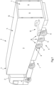
- the trailing arm axle arrangement 12 is shown during its manufacture, wherein the trailing arm axle arrangement 12 differs essentially by the design of the trailing arm 13 from the trailing arm axle arrangement according to Fig. 2 differs.
- an axle element 14 in the form of an axle tube is used, which has a circular cross-section and extends in a straight line between two longitudinal control arms 13, which are assigned to opposite ends of the axle element 14.
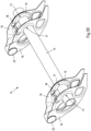
- Sheet metal elements 15, 16 are first pushed onto the axle element 14.
- a sheet metal element 15 is welded all the way around to the axle element 14.
- These sheet metal elements 15 are designed to be similar to one another.
- the inner sheet metal elements 16, which are also designed to be similar to one another, are simply pushed onto the axle element 14 but are not yet fixed to it.
- a damper mount 18 is welded to the axle element 14 for connecting a damper element.
- Two further outer sheet metal elements 16 are then pushed onto the axle element 14, which are designed in the same way as the two inner sheet metal elements 16.
- the inner sheet metal elements 16 and the outer sheet metal elements 16 are, as shown in the Fig. 3C shown, pushed towards the sheet metal elements 15 already welded to the axle element 14 in the assembly sections 17 and also welded all around to the axle element 14 in these positions.
- each assembly section 17 is created for each trailing arm 13, each with two sheet metal elements 15, 16 welded all the way around.
- the sheet metal elements 15, 16 of each assembly section 17 differ fundamentally from one another.
- an outer sheet metal element 16 as seen from the damper mount 18 is designed in the form of a shell element, which later forms at least a significant part of a side wall of the trailing arm 12, while the other sheet metal element 15, which is therefore assigned to the damper mount 18, is designed in the form of a reinforcing ring.
- These sheet metal elements then serve mainly to stiffen the connection between the axle element 14 and the trailing arm 13 in the corresponding assembly sections 17.
- the two sheet metal elements 15, 16 of each assembly section 17 come at least almost into contact with one another in order to then be welded together in the corresponding contact area.
- This welded connection 19 can also be made at least substantially all the way around the axle element 14.
- the at least substantially all the way around welded connection 19 between the sheet metal elements 15, 16 is made at a radial distance from the axle element 14.
- the at least substantially all the way around welded connection 19 between the sheet metal elements 15, 16 of an assembly section 17 is made in the method shown and preferred in this respect by a large number of welding points, while the welded connections 20, 21 between the sheet metal elements 15, 16 of the assembly sections 17 and the axle element 14 are formed by continuous, all the way around weld seams.
- the sheet metal elements 15,16 are shaped such that the sheet metal elements 15,16 of a mounting element 17 in the connection with the axle element 14 are spaced apart from one another in the longitudinal direction of the axle element 14.
- a bushing 22 is welded to the sheet metal elements 16 of each longitudinal member, which are designed in the form of shell elements, with which the longitudinal control arms 13 can be pivotally connected to corresponding consoles of the chassis. This is shown in the Fig.3D shown.
- the sheet metal elements 16 designed as shell elements and the bushing 22 of each trailing arm 13 are welded to a lower flange 24 and an upper flange 25.
- the lower flanges 24 and the upper flanges 25 thus connect the two sheet metal elements 16 designed as shell elements of each trailing arm 13 to one another, just like the bushing 22.
- the upper flange 25 forms a mounting area 26 for mounting a spring device with which the trailing arm axle arrangement 12 is attached to the chassis 8 of the commercial vehicle 1.
- through openings 27 are provided in the sheet metal elements 16 designed as shell elements and in the lower flanges 24 and the upper flanges 25.
- the through-openings 27 always have a circumferential edge bent inwards, which stiffens the corresponding sheet metal part 16, 24, 25.
- the finished longitudinal control arms 13 are thus formed in the manner of a box profile.
- a sectional view of the trailing arm axle arrangement 12 is shown longitudinally to the axle element 14 and transversely to the trailing arm 13.
- the sheet metal elements 15, 16 are each welded to the axle element 14 at a distance from one another in the longitudinal direction of the axle element 14 and at a radial distance from the axle element 14 via welded joints 19-21.
- the sheet metal elements 15, 16 of an assembly section 17 and the axle element 14 thus each form hollow spaces 28 in the assembly sections 17, which ensure a rigid connection of the trailing arms 13 to the axle element 14.
Landscapes
- Engineering & Computer Science (AREA)
- Mechanical Engineering (AREA)
- Vehicle Body Suspensions (AREA)
Priority Applications (1)
| Application Number | Priority Date | Filing Date | Title |
|---|---|---|---|
| EP23158522.5A EP4420901A1 (fr) | 2023-02-24 | 2023-02-24 | Essieu à bras oscillants longitudinaux et son procédé de fabrication |
Applications Claiming Priority (1)
| Application Number | Priority Date | Filing Date | Title |
|---|---|---|---|
| EP23158522.5A EP4420901A1 (fr) | 2023-02-24 | 2023-02-24 | Essieu à bras oscillants longitudinaux et son procédé de fabrication |
Publications (1)
| Publication Number | Publication Date |
|---|---|
| EP4420901A1 true EP4420901A1 (fr) | 2024-08-28 |
Family
ID=85382500
Family Applications (1)
| Application Number | Title | Priority Date | Filing Date |
|---|---|---|---|
| EP23158522.5A Pending EP4420901A1 (fr) | 2023-02-24 | 2023-02-24 | Essieu à bras oscillants longitudinaux et son procédé de fabrication |
Country Status (1)
| Country | Link |
|---|---|
| EP (1) | EP4420901A1 (fr) |
Citations (3)
| Publication number | Priority date | Publication date | Assignee | Title |
|---|---|---|---|---|
| DE69426991T2 (de) * | 1994-04-14 | 2001-10-25 | Holland Neway International, Inc. | Längsarmaufhängung |
| DE19781757B4 (de) * | 1996-05-09 | 2011-03-31 | Meritor Heavy Vehicle Suspension Systems, Inc., , Canal Fulton | Aufhängungssystem |
| US20190047343A1 (en) * | 2017-08-14 | 2019-02-14 | Hendrickson Usa, L.L.C. | Beam for suspension assemblies of heavy-duty vehicle axle/suspension systems |
-
2023
- 2023-02-24 EP EP23158522.5A patent/EP4420901A1/fr active Pending
Patent Citations (3)
| Publication number | Priority date | Publication date | Assignee | Title |
|---|---|---|---|---|
| DE69426991T2 (de) * | 1994-04-14 | 2001-10-25 | Holland Neway International, Inc. | Längsarmaufhängung |
| DE19781757B4 (de) * | 1996-05-09 | 2011-03-31 | Meritor Heavy Vehicle Suspension Systems, Inc., , Canal Fulton | Aufhängungssystem |
| US20190047343A1 (en) * | 2017-08-14 | 2019-02-14 | Hendrickson Usa, L.L.C. | Beam for suspension assemblies of heavy-duty vehicle axle/suspension systems |
Similar Documents
| Publication | Publication Date | Title |
|---|---|---|
| EP1448426B1 (fr) | Chassis modulaire de vehicules utilitaires | |
| EP2881307B1 (fr) | Agencement de faux-châssis pour un véhicule | |
| DE10219275B4 (de) | Fahrgestell für ein Nutzfahrzeug | |
| DE102012007325A1 (de) | Radaufhängung für eine Fünflenker-Hinterachse eines zweispurigen Fahrzeugs | |
| DE112011100227T5 (de) | Schwerlastachsen-/Aufhängungssystem | |
| EP3257691A1 (fr) | Structure portante de train roulant de vehicule utilitaire et train roulant de vehicule utilitaire | |
| EP0940320B1 (fr) | Chassis pour véhicule utilitaire lourd | |
| DE3521361C2 (fr) | ||
| DE102016111308B4 (de) | Fahrgestellanordnung und Landfahrzeug | |
| EP0940319B1 (fr) | Chassis d'un véhicule utilitaire lourd | |
| EP1562819B1 (fr) | Structure avant de vehicule automobile | |
| DE102006027722B3 (de) | Hauptlangträger-Segment | |
| EP4420901A1 (fr) | Essieu à bras oscillants longitudinaux et son procédé de fabrication | |
| EP0231761B1 (fr) | Remorque de camion | |
| EP1749678B1 (fr) | Corps d'essieu pour axes des véhicules utilitaires | |
| EP0940322B1 (fr) | Chassis pour véhicule utilitaire lourd | |
| EP0940324B1 (fr) | Chassis pour véhicule utilitaire lourd | |
| DE19809196A1 (de) | Fahrgestell eines schweren Nutzfahrzeuges | |
| EP4261112B1 (fr) | Structure de support d'essieu, utilisation d'un tel support d'essieu et procédé de sa fabrication | |
| DE202015102551U1 (de) | Achsanordnung | |
| DE19809268A1 (de) | Fahrgestell eines schweren Nutzfahrzeuges | |
| WO2006061107A2 (fr) | Structure de support | |
| DE202008016610U1 (de) | Distanzstück zur Spurverbreiterung und/oder zur Tieferlegung eines Kraftfahrzeuges | |
| DE102015113973B4 (de) | Rahmenanordnung | |
| DE102023107343A1 (de) | Fahrzeugstarrachse mit Federung |
Legal Events
| Date | Code | Title | Description |
|---|---|---|---|
| PUAI | Public reference made under article 153(3) epc to a published international application that has entered the european phase |
Free format text: ORIGINAL CODE: 0009012 |
|
| STAA | Information on the status of an ep patent application or granted ep patent |
Free format text: STATUS: THE APPLICATION HAS BEEN PUBLISHED |
|
| AK | Designated contracting states |
Kind code of ref document: A1 Designated state(s): AL AT BE BG CH CY CZ DE DK EE ES FI FR GB GR HR HU IE IS IT LI LT LU LV MC ME MK MT NL NO PL PT RO RS SE SI SK SM TR |
|
| STAA | Information on the status of an ep patent application or granted ep patent |
Free format text: STATUS: REQUEST FOR EXAMINATION WAS MADE |
|
| 17P | Request for examination filed |
Effective date: 20250210 |