EP4420944A1 - Filteranordnung für ein druckluftaufbereitungssystem eines fahrzeugs - Google Patents
Filteranordnung für ein druckluftaufbereitungssystem eines fahrzeugs Download PDFInfo
- Publication number
- EP4420944A1 EP4420944A1 EP23158375.8A EP23158375A EP4420944A1 EP 4420944 A1 EP4420944 A1 EP 4420944A1 EP 23158375 A EP23158375 A EP 23158375A EP 4420944 A1 EP4420944 A1 EP 4420944A1
- Authority
- EP
- European Patent Office
- Prior art keywords
- wall
- air treatment
- flange
- filter assembly
- central
- Prior art date
- Legal status (The legal status is an assumption and is not a legal conclusion. Google has not performed a legal analysis and makes no representation as to the accuracy of the status listed.)
- Pending
Links
- 238000011282 treatment Methods 0.000 title claims abstract description 87
- 230000002093 peripheral effect Effects 0.000 claims abstract description 6
- 238000007789 sealing Methods 0.000 claims description 12
- 238000000034 method Methods 0.000 description 5
- 239000002274 desiccant Substances 0.000 description 2
- 238000004049 embossing Methods 0.000 description 2
- 238000001914 filtration Methods 0.000 description 2
- 238000003801 milling Methods 0.000 description 2
- 230000002542 deteriorative effect Effects 0.000 description 1
- 239000002184 metal Substances 0.000 description 1
- 238000004826 seaming Methods 0.000 description 1
- 229910001220 stainless steel Inorganic materials 0.000 description 1
- 239000010935 stainless steel Substances 0.000 description 1
- 239000000725 suspension Substances 0.000 description 1
Images




Classifications
-
- B—PERFORMING OPERATIONS; TRANSPORTING
- B60—VEHICLES IN GENERAL
- B60T—VEHICLE BRAKE CONTROL SYSTEMS OR PARTS THEREOF; BRAKE CONTROL SYSTEMS OR PARTS THEREOF, IN GENERAL; ARRANGEMENT OF BRAKING ELEMENTS ON VEHICLES IN GENERAL; PORTABLE DEVICES FOR PREVENTING UNWANTED MOVEMENT OF VEHICLES; VEHICLE MODIFICATIONS TO FACILITATE COOLING OF BRAKES
- B60T17/00—Component parts, details, or accessories of power brake systems not covered by groups B60T8/00, B60T13/00 or B60T15/00, or presenting other characteristic features
- B60T17/002—Air treatment devices
- B60T17/004—Draining and drying devices
Definitions
- the present invention relates to a filter assembly for a compressed air treatment system of vehicle, especially for utility vehicles.
- compressed air treatment systems are commonly used in brake systems and air suspension systems of vehicles, e.g. the utility vehicles such as trucks.
- Such compressed air treatment systems typically comprise a disposable air dryer cartridge mounted onto an air dryer treatment device.
- EP 2 448 801 A1 discloses an air dryer cartridge for a compressed air treatment system of a vehicle, comprising a spring cover and a carrier element, which together define a volume of the air dryer cartridge in the assembled state of the air dryer cartridge, wherein a desiccant box arranged inside the volume and filled with a desiccant.
- EP 3 433 001 B1 discloses securing means in the form of a bayonet lock.
- the securing means comprises a plurality of fastening means provided on a filter element that can be secured to a plurality of head pins provided on a filter module.
- the fastening means have a specific arc-shaped guide grooves including inclined portions having an upward gradient towards a latching contour.
- the filter assembly enables a reliable and easy assembling and disassembling of an air dryer cartridge onto an air dryer treatment device.
- the air dryer cartridge can quickly be secured in an accurate manner without creating unbalanced loads within the filter assembly and without the use of advanced tools.
- the filter assembly comprises an air dryer cartridge that is configured to be removably secured onto an air treatment device.
- the air treatment device comprises a housing including a peripheral portion and a central portion, wherein the central portion includes a central wall that defines an outer wall surface.
- the air dryer cartridge comprises a flange base portion and a flange neck portion, wherein the flange neck portion includes a flange wall extending from the flange base portion and defining an inner neck surface.
- the flange neck portion is configured to (e.g.
- the filter assembly further comprises a guiding element that is included in the flange neck portion of the air dryer cartridge or on the central wall of the air treatment device.
- the guiding element is configured to guide the flange neck portion onto the central wall of the air treatment device up to a defined end position.
- the invention is based on the basic idea that a filter assembly for a compressed air system of vehicle is provided that can be assembled and disassembled in an accurate and reliable manner.
- the filter assembly comprises an air dryer cartridge that can easily be secured onto an air treatments device and removed therefrom.
- the air treatment device comprises a housing includes a peripheral portion and a central portion having a central wall.
- the air dryer cartridge comprises a flange neck portion having a flange wall extending from a flange base portion.
- the air dryer cartridge includes a guiding element provided in the flange neck portion of the air dryer cartridge or on the central wall of the air treatment device for a uniform guidance of its movements (e.g. sliding movements or rotation) of the flange neck portion onto the central wall of the air treatment device.
- a uniform guidance of its movements e.g. sliding movements or rotation
- the flange neck portion onto the central wall of the air treatment device.
- the air dryer cartridge and the air treatment device are symmetrically arranged with respect to a central axis.
- the air dryer cartridge is advantageously configured to move (rotate or slide) onto the central wall of the air treatment device and to rotate thereon in a movement direction around the central axis up to a defined end position.
- the guiding element comprises at least two grooved surfaces (e.g. cut-out surfaces) for example with curved boundaries that are arranged around the central axis of the filter assembly.
- grooved surfaces e.g. cut-out surfaces
- Such grooved surfaces with a defined shape and dimension can easily be created onto the walls of the filter assembly using techniques such as milling or embossing.
- the tab element comprises at least two projections that are arranged around the central axis of the filter assembly (e.g. symmetrically or asymmetric).
- the at least two projections of the tab element are configured, for example to smoothly slide or move on the corresponding grooved surfaces of the guiding element. In this way the relative movement of the air dryer cartridges on to the air treatment device can easily and uniformly be controlled.
- the flange neck portion further comprises an insert element including an insert wall that is configured to be fitted within the flange wall of the flange neck portion, wherein the insert wall defines an insert inner surface and an insert outer surface.
- the insert outer surface is configured to be connected to the inner neck surface of the flange wall, and the insert inner surface is configured to be engaged with the outer wall surface of the central wall.
- the inner surface of the flange wall comprises a plurality of grooved channels configured to receive a plurality of projected channels included on the insert outer surface, wherein the plurality of the grooved channels and the plurality of projected channels are arranged around the central axis of the filter assembly and extend in a direction in parallel thereto.
- the insert elements of various dimension or shape of insert inner surfaces can uniformly be mounted via the outer surface onto the flange wall.
- the guiding element can be included on the inner neck surface of the flange wall, on the insert inner surface of the insert wall or on the outer wall surface of the central wall.
- the guiding element is included on the inner neck surface of the flange wall or on the insert inner surface of the insert wall.
- the tab element is formed by a pin that is configured to extend through two through-holes formed onto the central wall of the air treatment device.
- the tab element is preferably configured to removably be secured within the through-holes with its ends projecting from the outer surface of the central wall.
- the projecting ends of the pin are configured to engage with (e.g. smoothly slide on) the grooved surfaces provided on the inner neck surface or on the insert inner surface of the air dryer cartridge.
- the guiding element is included on the outer wall surface of the central wall.
- the tab element is formed on the inner surface of the flange wall of the air dryer cartridge.
- the tab element comprises at least two projections that are projecting inwardly from the inner neck surface.
- these projections are configured to engage with the corresponding grooved surfaces provided on the outer surface of the central wall of the air treatment device.
- the design and structural features of filter assembly i.e. the air dryer cartridge and the air treatment device can be varied as required without jeopardizing the reliability of the filtering performance or the practicability of its design.
- the filter assembly further comprises a fixing element for locking relative movements of the flange neck portion of the air dryer cartridge with respect to the central portion of the air treatment device.
- the central wall of the air treatment device includes at least holes (e.g. two blind-holes) that are formed onto the outer surface of the central wall
- the flange wall of the air dryer cartridge includes at least two through-holes that are formed onto the flange wall (e.g. opposite sides of the flange wall).
- the fixing element comprises at least two pins, each being configured to be inserted into a through-hole of the flange wall and a corresponding hole or blind-hole of the central wall.
- the pins are further configured to removably be secured in the holes of the flange wall and the central wall. In this way the air dryer cartridge is advantageously further secured/fixed onto the air treatment device.
- pins are metal pins, e.g. stainless steel roll pins or spring pins.
- the flange base portion comprises a plurality of openings configured to be engaged with a corresponding plurality of pin elements that are included in the housing of the air treatment device when mounting the flange neck portion onto the central portion of the housing.
- the plurality of openings includes three openings arranged around the central axis of the filter assembly
- the plurality of pin elements includes three pin elements that are arranged around the central axis of the filter assembly.
- each of the plurality of openings define a curved opening on the flange base portion and have a first end and a second end.
- the second end comprises a thickened contour, preferably in the shape of a horseshoe, for contacting with (engaging with) the corresponding pin element of the air treatment device.
- the pin elements are held at the second ends of the openings, resulting in an easier handling, and fixing of the air dryer cartridge onto the air treatment device.
- the pin elements include for example a pin, a threaded pin, a screw or a nail.
- the insert wall comprises a first circumferential shoulder configured to receive a first sealing element on the outer insert surface.
- the insert wall may comprise a second circumferential shoulder configured to receive a fixing element on the outer insert surface.
- the central wall of the air treatment device comprises a third circumferential shoulder configured to receive a second sealing element on the outer wall surface.
- the provision of the shoulders on the insert wall and/or on the central wall for receiving the sealing elements, such as sealing rings or O rings, advantageously provides for an easy servicing in that no seaming or retightening or mechanical tools are required.
- the fixing element e.g. or Seeger ring
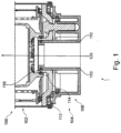
- Fig. 1 a schematic partial cross-sectional view of a known filter assembly 100 of a compressed air treatment system of a vehicle, e.g. a utility vehicle, is shown.
- the filter assembly 100 comprises an air dryer cartridge 102 and an air treatment device 104.
- the air dryer cartridge 102 is configured to be removably secured onto the air treatment device 104.
- the air treatment device 104 comprises a housing that includes a peripheral portion 106 and a central portion 108.
- the central portion 108 includes a central wall 110 (e.g. a hollow cylindrical wall) defining an outer wall surface (not visible in Fig. 1 ).
- the air dryer cartridge 102 comprises a flange base portion 112 and a flange neck portion 114 (e.g. a hollow cylindrical portion).
- the flange neck portion includes a flange wall 116 which extends from the flange base portion 112 along a central axis 120 (i.e. in a direction towards interior of the air dryer cartridge).
- the flange wall 116 defines an inner neck surface (not visible in Fig. 1 ).
- the flange neck portion 114 is configured to be mounted onto the central portion 108 of the housing of the air treatment device 104 such that the inner neck surface faces towards the outer wall surface of the central wall 110.
- Fig. 2 illustrates a schematic partial view of a flange base portion 112 of an air dryer cartridge 102 of a filter assembly according to the present invention.
- a guiding element 118 is provided.
- the guiding element 118 advantageously serves the purpose of an accurate guidance of the movements of the flange neck portion onto the central wall up to an end position that is defined by the guiding element, e.g. by its geometry, dimension or boundary.
- the guiding element 114 includes advantageously at least two grooved surfaces included in the flange neck portion 114 or on the central wall 110.
- the grooved surfaces i.e. the cut-out surfaces
- the grooved surfaces for example have curved boundaries and are symmetrically arranged around the central axis 120 of the filter assembly.
- the grooved surfaces can be for example created by milling or embossing techniques.
- Fig. 2 one of the grooved surfaces is shown in the flange neck portion 114 of the air dryer cartridge 102.
- the guiding element 118 is formed on the inner neck surface of the flange wall 116.
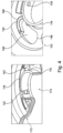
- Fig. 3 illustrates schematic partial views of an air treatment device 102 of the filter assembly according to the present invention in an unassembled state (the left panel in the figure) and an assembled state (in the right panel).
- the guiding element 118 i.e. the two grooved surfaces, is (are) formed on the outer wall surface of the central wall 110 of the air treatment device 104 (in Fig. 3 one of the grooved surfaces is partially visible).
- the filter assembly further comprises a fixing element for locking relative movements of the flange neck portion 114 of the air dryer cartridge 102 with respect to the central portion 108 of the housing of the air treatment device 102.
- the central wall 110 includes at least two holes (e.g. blind-holes) 136 that are formed onto the outer surface thereof.
- the flange wall 116 includes at least two through-holes 134 (see Fig. 4 ).
- the fixing element comprises at least two pins 152.
- Each of the pins are configured to be inserted into the through-hole of the flange wall 116 and into the corresponding hole 136 of the central wall 110.
- the pins 152 are further configured to be removably secured within the holes. In this way it is possible to further secure the flange neck portion 104 onto the central wall of the air treatment device 102.
- the flange base portion 112 of the air dryer cartridge further comprises a plurality of openings 142 that are configured to be engaged with a plurality of pin elements 144 of the housing of the air treatment device (see Fig. 3 , the left panel) when mounting the flange neck portion onto the central portion of the housing.
- a plurality of openings 142 that are configured to be engaged with a plurality of pin elements 144 of the housing of the air treatment device (see Fig. 3 , the left panel) when mounting the flange neck portion onto the central portion of the housing.
- the pin elements include for example, a pin, a threaded pin, a screw or a nail.
- Fig. 4 shows schematic partial views of the flange neck portion 114 of a filter assembly according to the present invention.
- the filter assembly further comprises a tab element 122 that is included in the flange neck portion 114.
- the tab element 122 is configured to move or to slide on the guiding element 118.
- the tab element 122 comprises at least two projections that are arranged around the central axis 120 of the filter assembly.
- the projections of the tab element 122 are projecting inwardly from the inner neck surface.
- the projections are advantageously configured to slide or to move on the corresponding grooved surfaces of the guiding element, when moving the air dryer cartridge onto the air treatment device. This in turn provides an easy and precise assembling of the filter assembly.
- the Fig. 4 further shows that one of the plurality of openings 142 formed on the flange base portion 112.
- Each of the openings define a curved opening (e.g. an arc-shaped recess) on the flange base portion 112 and include a first end 146 and a second end 148.
- each opening of the plurality of openings 142 comprises a thickened contour 150.
- the thickened contour 150 advantageously serves the purpose of contacting the corresponding pin element 144 of the air treatment device 102 which in turn results in a better engagement and an easy fixation of the air dryer cartridge onto the air treatment device.
- the contour 150 is for example formed in the shape of a horseshoe.
- Fig. 5 illustrates a schematic partial exploded-view of a flange neck portion 114 and a central wall 110 of a filter assembly according to the present invention.
- the inner surface of the flange wall 116 comprises a plurality of grooved channels 128 configured to receive a plurality of projected channels 130 included on the insert outer surface.
- the insert element advantageously is integrated onto the flange wall in a reliable and easy manner without using mechanical tools.
- Fig. 5 further shows that the guiding element 118 is included on the insert inner surface of the insert wall 126.
- the tab element 122 i.e., the projections thereof, is (are) formed by a pin 132 that is configured to extend through two through-holes onto opposite sides of the central wall 110.
- the pin 132 is configured to be removably secured within the through-holes with its ends projecting from the outer surface of the central wall 110.
- the tab element 122 is provided by the pin 132 arranged within the two through-holes of the central wall 110.
- the two ends of the pin 132 projecting outwardly from the outer surface of the central wall 110.
- the at least two through-holes are symmetrically arranged with respect to the central axis 120.
- Fig. 6 shows a schematic view of the filter assembly in an assembled state.
- the insert element 124 of the flange neck portion 114 The insert outer surface of the insert wall 126 is connected with the inner surface of the flange wall 116 via the grooved channels 128 and the corresponding projected channels 130.
- the insert inner surface of the insert wall 126 is engaged with the outer surface of the central wall via the tab element 122, i.e. the projected ends thereof.
- the air dryer cartridge 102 is reliably mounted onto the air treatment device and no excess or unbalanced loads are created in the filter assembly during the assembling process.
- the filter assembly can easily be disassembled as the tab element is guided on the guiding surfaces of the guiding element.
- the insert wall 126 comprises a first circumferential shoulder 138 that is configured to receive a first sealing element 154, e.g. a sealing ring or an O-ring, on the insert outer surface.
- a first sealing element 154 e.g. a sealing ring or an O-ring
- the insert wall 126 further comprises a second circumferential shoulder 140 that is configured to receive a fixing element 156, e.g. a Seeger ring, on the insert outer surface.
- a fixing element 156 serves the purpose of fixing or securing the position of the insert element 124 onto the flange wall 116.
- the central wall 110 comprises a third circumferential shoulder 158 that is configured to receive a second sealing element 160 on the outer wall surface thereof.
Landscapes
- Engineering & Computer Science (AREA)
- Transportation (AREA)
- Mechanical Engineering (AREA)
- Filtering Of Dispersed Particles In Gases (AREA)
Priority Applications (1)
| Application Number | Priority Date | Filing Date | Title |
|---|---|---|---|
| EP23158375.8A EP4420944A1 (de) | 2023-02-24 | 2023-02-24 | Filteranordnung für ein druckluftaufbereitungssystem eines fahrzeugs |
Applications Claiming Priority (1)
| Application Number | Priority Date | Filing Date | Title |
|---|---|---|---|
| EP23158375.8A EP4420944A1 (de) | 2023-02-24 | 2023-02-24 | Filteranordnung für ein druckluftaufbereitungssystem eines fahrzeugs |
Publications (1)
| Publication Number | Publication Date |
|---|---|
| EP4420944A1 true EP4420944A1 (de) | 2024-08-28 |
Family
ID=85382808
Family Applications (1)
| Application Number | Title | Priority Date | Filing Date |
|---|---|---|---|
| EP23158375.8A Pending EP4420944A1 (de) | 2023-02-24 | 2023-02-24 | Filteranordnung für ein druckluftaufbereitungssystem eines fahrzeugs |
Country Status (1)
| Country | Link |
|---|---|
| EP (1) | EP4420944A1 (de) |
Citations (3)
| Publication number | Priority date | Publication date | Assignee | Title |
|---|---|---|---|---|
| US7972418B2 (en) * | 2006-08-08 | 2011-07-05 | Knorr-Bremse Systeme Fuer Nutzfahrzeuge Gmbh | Compressed air supply device |
| EP2448801A1 (de) | 2009-06-29 | 2012-05-09 | KNORR-BREMSE Systeme für Nutzfahrzeuge GmbH | Luftrocknerpatrone für eine druckluftaufbereitungsanlage eines fahrzeugs |
| EP3433001B1 (de) | 2016-03-24 | 2020-07-08 | Daimler AG | Filtereinrichtung für eine filteranlage eines kraftwagens |
-
2023
- 2023-02-24 EP EP23158375.8A patent/EP4420944A1/de active Pending
Patent Citations (4)
| Publication number | Priority date | Publication date | Assignee | Title |
|---|---|---|---|---|
| US7972418B2 (en) * | 2006-08-08 | 2011-07-05 | Knorr-Bremse Systeme Fuer Nutzfahrzeuge Gmbh | Compressed air supply device |
| EP2448801A1 (de) | 2009-06-29 | 2012-05-09 | KNORR-BREMSE Systeme für Nutzfahrzeuge GmbH | Luftrocknerpatrone für eine druckluftaufbereitungsanlage eines fahrzeugs |
| EP3433001B1 (de) | 2016-03-24 | 2020-07-08 | Daimler AG | Filtereinrichtung für eine filteranlage eines kraftwagens |
| US10898832B2 (en) * | 2016-03-24 | 2021-01-26 | Daimler Ag | Filter device for a filter system of a motor vehicle |
Similar Documents
| Publication | Publication Date | Title |
|---|---|---|
| EP3643386B1 (de) | Verbessertes ölfilter | |
| US2486411A (en) | Fastener | |
| CN110131509B (zh) | 流体连接装置 | |
| JP4733709B2 (ja) | タービンロータにおけるロータ軸方向セグメント | |
| CN104832547B (zh) | 轴承装置及形成轴承装置的方法 | |
| KR101732340B1 (ko) | 브레이크 디스크 | |
| EP2763246B1 (de) | Drehbare konnektorvorrichtung | |
| JPH022483B2 (de) | ||
| JP6637616B2 (ja) | 自動車のフィルタシステムのためのフィルタデバイス | |
| TW202144201A (zh) | 閥 | |
| JP2008169838A6 (ja) | タービンロータにおけるロータ軸方向セグメント | |
| CN111619793B (zh) | 设有隔热罩的飞行器轮子 | |
| JP2003326176A (ja) | 試験管保持用アダプター | |
| BR0311636B1 (pt) | conjunto de guias de perfuração para conduzir a remoção de uma placa extratora. | |
| US20050037888A1 (en) | Differential and method for assembling said differential | |
| EP3270204A1 (de) | Objektivtubus und verfahren zur einstellung der optischen achse | |
| IT201800007689A1 (it) | Cartuccia filtrante con organi d’impegno | |
| WO2016194946A1 (ja) | フィルタ装置 | |
| JP2025515927A (ja) | フィルタシステム及びフィルタ要素 | |
| US4475337A (en) | Rapid-assembly braking control unit | |
| JP7087961B2 (ja) | 車両用コネクタ | |
| US4244451A (en) | Disc brake and pin assembly therefor | |
| US9675908B2 (en) | Fuel filter assembly and cartridge | |
| US20220252118A1 (en) | Brake Dust Particle Filter Assembly, Disc Brake Assembly Comprising a Brake Dust Particle Filter Assembly, and Vehicle Comprising a Disc Brake Assembly | |
| US20210236680A1 (en) | Fragrancing device |
Legal Events
| Date | Code | Title | Description |
|---|---|---|---|
| PUAI | Public reference made under article 153(3) epc to a published international application that has entered the european phase |
Free format text: ORIGINAL CODE: 0009012 |
|
| STAA | Information on the status of an ep patent application or granted ep patent |
Free format text: STATUS: THE APPLICATION HAS BEEN PUBLISHED |
|
| AK | Designated contracting states |
Kind code of ref document: A1 Designated state(s): AL AT BE BG CH CY CZ DE DK EE ES FI FR GB GR HR HU IE IS IT LI LT LU LV MC ME MK MT NL NO PL PT RO RS SE SI SK SM TR |
|
| STAA | Information on the status of an ep patent application or granted ep patent |
Free format text: STATUS: REQUEST FOR EXAMINATION WAS MADE |
|
| 17P | Request for examination filed |
Effective date: 20250228 |