EP4421288A2 - Tête de coupe à disque de coupe segmenté - Google Patents
Tête de coupe à disque de coupe segmenté Download PDFInfo
- Publication number
- EP4421288A2 EP4421288A2 EP24188575.5A EP24188575A EP4421288A2 EP 4421288 A2 EP4421288 A2 EP 4421288A2 EP 24188575 A EP24188575 A EP 24188575A EP 4421288 A2 EP4421288 A2 EP 4421288A2
- Authority
- EP
- European Patent Office
- Prior art keywords
- cutting
- disc body
- cutting portion
- replacement
- portions
- Prior art date
- Legal status (The legal status is an assumption and is not a legal conclusion. Google has not performed a legal analysis and makes no representation as to the accuracy of the status listed.)
- Pending
Links
Images




Classifications
-
- E—FIXED CONSTRUCTIONS
- E21—EARTH OR ROCK DRILLING; MINING
- E21C—MINING OR QUARRYING
- E21C25/00—Cutting machines, i.e. for making slits approximately parallel or perpendicular to the seam
- E21C25/16—Machines slitting solely by one or more rotating saws, cutting discs, or wheels
-
- E—FIXED CONSTRUCTIONS
- E21—EARTH OR ROCK DRILLING; MINING
- E21C—MINING OR QUARRYING
- E21C27/00—Machines which completely free the mineral from the seam
- E21C27/20—Mineral freed by means not involving slitting
-
- E—FIXED CONSTRUCTIONS
- E21—EARTH OR ROCK DRILLING; MINING
- E21C—MINING OR QUARRYING
- E21C27/00—Machines which completely free the mineral from the seam
- E21C27/20—Mineral freed by means not involving slitting
- E21C27/24—Mineral freed by means not involving slitting by milling means acting on the full working face, i.e. the rotary axis of the tool carrier being substantially parallel to the working face
-
- E—FIXED CONSTRUCTIONS
- E21—EARTH OR ROCK DRILLING; MINING
- E21C—MINING OR QUARRYING
- E21C35/00—Details of, or accessories for, machines for slitting or completely freeing the mineral from the seam, not provided for in groups E21C25/00 - E21C33/00, E21C37/00 or E21C39/00
- E21C35/18—Mining picks; Holders therefor
-
- E—FIXED CONSTRUCTIONS
- E21—EARTH OR ROCK DRILLING; MINING
- E21C—MINING OR QUARRYING
- E21C35/00—Details of, or accessories for, machines for slitting or completely freeing the mineral from the seam, not provided for in groups E21C25/00 - E21C33/00, E21C37/00 or E21C39/00
- E21C35/18—Mining picks; Holders therefor
- E21C35/183—Mining picks; Holders therefor with inserts or layers of wear-resisting material
- E21C35/1837—Mining picks; Holders therefor with inserts or layers of wear-resisting material characterised by the shape
-
- E—FIXED CONSTRUCTIONS
- E21—EARTH OR ROCK DRILLING; MINING
- E21C—MINING OR QUARRYING
- E21C35/00—Details of, or accessories for, machines for slitting or completely freeing the mineral from the seam, not provided for in groups E21C25/00 - E21C33/00, E21C37/00 or E21C39/00
- E21C35/18—Mining picks; Holders therefor
- E21C35/19—Means for fixing picks or holders
-
- E—FIXED CONSTRUCTIONS
- E21—EARTH OR ROCK DRILLING; MINING
- E21D—SHAFTS; TUNNELS; GALLERIES; LARGE UNDERGROUND CHAMBERS
- E21D9/00—Tunnels or galleries, with or without linings; Methods or apparatus for making thereof; Layout of tunnels or galleries
- E21D9/10—Making by using boring or cutting machines
- E21D9/1006—Making by using boring or cutting machines with rotary cutting tools
- E21D9/1013—Making by using boring or cutting machines with rotary cutting tools on a tool-carrier supported by a movable boom
- E21D9/102—Making by using boring or cutting machines with rotary cutting tools on a tool-carrier supported by a movable boom by a longitudinally extending boom being pivotable about a vertical and a transverse axis
-
- B—PERFORMING OPERATIONS; TRANSPORTING
- B26—HAND CUTTING TOOLS; CUTTING; SEVERING
- B26D—CUTTING; DETAILS COMMON TO MACHINES FOR PERFORATING, PUNCHING, CUTTING-OUT, STAMPING-OUT OR SEVERING
- B26D1/00—Cutting through work characterised by the nature or movement of the cutting member or particular materials not otherwise provided for; Apparatus or machines therefor; Cutting members therefor
- B26D1/0006—Cutting members therefor
- B26D2001/0046—Cutting members therefor rotating continuously about an axis perpendicular to the edge
-
- E—FIXED CONSTRUCTIONS
- E02—HYDRAULIC ENGINEERING; FOUNDATIONS; SOIL SHIFTING
- E02F—DREDGING; SOIL-SHIFTING
- E02F5/00—Dredgers or soil-shifting machines for special purposes
- E02F5/16—Machines for digging other holes in the soil
- E02F5/18—Machines for digging other holes in the soil for horizontal holes or inclined holes
-
- E—FIXED CONSTRUCTIONS
- E02—HYDRAULIC ENGINEERING; FOUNDATIONS; SOIL SHIFTING
- E02F—DREDGING; SOIL-SHIFTING
- E02F5/00—Dredgers or soil-shifting machines for special purposes
- E02F5/16—Machines for digging other holes in the soil
- E02F5/20—Machines for digging other holes in the soil for vertical holes
-
- E—FIXED CONSTRUCTIONS
- E02—HYDRAULIC ENGINEERING; FOUNDATIONS; SOIL SHIFTING
- E02F—DREDGING; SOIL-SHIFTING
- E02F9/00—Component parts of dredgers or soil-shifting machines, not restricted to one of the kinds covered by groups E02F3/00 - E02F7/00
- E02F9/28—Small metalwork for digging elements, e.g. teeth scraper bits
- E02F9/2866—Small metalwork for digging elements, e.g. teeth scraper bits for rotating digging elements
-
- E—FIXED CONSTRUCTIONS
- E21—EARTH OR ROCK DRILLING; MINING
- E21B—EARTH OR ROCK DRILLING; OBTAINING OIL, GAS, WATER, SOLUBLE OR MELTABLE MATERIALS OR A SLURRY OF MINERALS FROM WELLS
- E21B3/00—Rotary drilling
- E21B3/02—Surface drives for rotary drilling
-
- E—FIXED CONSTRUCTIONS
- E21—EARTH OR ROCK DRILLING; MINING
- E21B—EARTH OR ROCK DRILLING; OBTAINING OIL, GAS, WATER, SOLUBLE OR MELTABLE MATERIALS OR A SLURRY OF MINERALS FROM WELLS
- E21B3/00—Rotary drilling
- E21B3/02—Surface drives for rotary drilling
- E21B3/03—Surface drives for rotary drilling with an intermittent unidirectional rotation of the tool
-
- E—FIXED CONSTRUCTIONS
- E21—EARTH OR ROCK DRILLING; MINING
- E21C—MINING OR QUARRYING
- E21C25/00—Cutting machines, i.e. for making slits approximately parallel or perpendicular to the seam
- E21C25/06—Machines slitting solely by one or more cutting rods or cutting drums which rotate, move through the seam, and may or may not reciprocate
-
- E—FIXED CONSTRUCTIONS
- E21—EARTH OR ROCK DRILLING; MINING
- E21C—MINING OR QUARRYING
- E21C25/00—Cutting machines, i.e. for making slits approximately parallel or perpendicular to the seam
- E21C25/16—Machines slitting solely by one or more rotating saws, cutting discs, or wheels
- E21C25/18—Saws; Discs; Wheels
-
- E—FIXED CONSTRUCTIONS
- E21—EARTH OR ROCK DRILLING; MINING
- E21C—MINING OR QUARRYING
- E21C27/00—Machines which completely free the mineral from the seam
- E21C27/02—Machines which completely free the mineral from the seam solely by slitting
-
- E—FIXED CONSTRUCTIONS
- E21—EARTH OR ROCK DRILLING; MINING
- E21C—MINING OR QUARRYING
- E21C27/00—Machines which completely free the mineral from the seam
- E21C27/10—Machines which completely free the mineral from the seam by both slitting and breaking-down
- E21C27/14—Machines which completely free the mineral from the seam by both slitting and breaking-down breaking-down effected by force or pressure applied to side of slit, e.g. by wedges
- E21C27/16—Machines which completely free the mineral from the seam by both slitting and breaking-down breaking-down effected by force or pressure applied to side of slit, e.g. by wedges with means for both slitting and breaking-down
-
- E—FIXED CONSTRUCTIONS
- E21—EARTH OR ROCK DRILLING; MINING
- E21C—MINING OR QUARRYING
- E21C31/00—Driving means incorporated in machines for slitting or completely freeing the mineral from the seam
- E21C31/02—Driving means incorporated in machines for slitting or completely freeing the mineral from the seam for cutting or breaking-down devices
-
- E—FIXED CONSTRUCTIONS
- E21—EARTH OR ROCK DRILLING; MINING
- E21D—SHAFTS; TUNNELS; GALLERIES; LARGE UNDERGROUND CHAMBERS
- E21D9/00—Tunnels or galleries, with or without linings; Methods or apparatus for making thereof; Layout of tunnels or galleries
- E21D9/10—Making by using boring or cutting machines
- E21D9/1006—Making by using boring or cutting machines with rotary cutting tools
- E21D9/1013—Making by using boring or cutting machines with rotary cutting tools on a tool-carrier supported by a movable boom
Definitions
- the present disclosure relates to machines for mining or excavating rock, and more particularly to a cutting mechanism for mining or excavating rock.
- Mining machines may incorporate a cutting disc for cutting and removing rock and/or mineral.
- the cutting disc may be rotated and driven to undercut the rock face at a narrow angle to generate shearing forces to cause the rock to fracture.
- the cutting disc has a plurality of bits or buttons positioned on a periphery of the disc.
- a cutting device for engaging a rock face includes a disc body supported for rotation about an axis of rotation, and a plurality of peripheral portions removably secured to the disc body.
- Each of the peripheral portions including a plurality of cutting bits positioned on a peripheral edge. The peripheral edge of each peripheral portion is aligned with the peripheral edges of adjacent peripheral portions.
- a cutting head for engaging a rock wall includes a boom configured to be supported on a frame, a drive mechanism, and a cutting device supported on the boom and driven by the drive mechanism.
- the cutting device includes a disc body supported for rotation about an axis of rotation, and a plurality of peripheral portions removably secured to the disc body.
- Each of the peripheral portions includes a plurality of cutting bits positioned on a peripheral edge. The peripheral edge of each peripheral portion is aligned with the peripheral edges of adjacent peripheral portions.
- a cutting device for engaging a rock face includes a disc body supported for rotation about an axis of rotation, and a cutting member supported on the disc body.
- the cutting member includes a peripheral edge and a plurality of cutting bits positioned along the peripheral edge, and the peripheral edge has a round shape.
- the cutting member is formed as a plurality of cutting portions independently and removably secured to the disc body, each of the cutting portions supporting some of the cutting bits.
- a method for servicing a cutting device for a mining machine.
- the cutting device includes a plurality of cutting portions supported on a disc body, and each cutting portion includes a plurality of cutting bits positioned along a peripheral edge.
- the method includes uncoupling one of the cutting portions from the disc body, and securing a replacement cutting portion to the disc body in a position previously occupied by the one cutting portion.
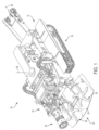
- FIG. 1 illustrates a mining machine 10 (e.g., an entry development machine) including a frame or chassis 14, a boom 18, and a cutting head 22 supported on the boom 18 for engaging and removing rock from a rock face (not shown).
- the chassis 14 is supported on a drive system including traction devices, such as crawlers or tracks 30 for moving the chassis 14 over a support surface or floor.
- the chassis 14 includes a first or forward end and a second or rear end, and a longitudinal chassis axis 26 extends between the forward end and the rear end.
- the chassis 14 further includes a gathering head 32 positioned adjacent the mine floor proximate the cutting head 22.
- the gathering head 32 includes a deck 34 and rotating members 38 that direct cut material from the deck 34 onto a conveyor 42.
- the chassis 14 may also include arms for directing cut material onto the deck 34.
- the mining machine 10 includes a single cutting head; in other embodiments, the machine 10 may include multiple cutting heads.
- the boom 18 may be supported on the chassis 14 by a turntable or swivel joint that is rotatable about a swivel axis 56 perpendicular to the chassis axis 26 (e.g., a vertical axis perpendicular to the support surface) to pivot the boom 18 in a plane that is generally parallel the chassis axis 26 (e.g., a horizontal plane parallel to the support surface).
- a turntable or swivel joint that is rotatable about a swivel axis 56 perpendicular to the chassis axis 26 (e.g., a vertical axis perpendicular to the support surface) to pivot the boom 18 in a plane that is generally parallel the chassis axis 26 (e.g., a horizontal plane parallel to the support surface).
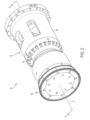
- the cutting head 22 includes a housing 52 coupled to the end of the boom 18 ( FIG. 1 ), an exciter assembly 54 ( FIG. 4 ), and a cutting disc assembly 58.
- the cutting head 22 extends along a cutting head axis A.
- the housing 52 includes a cylindrical portion 60 and an arm 62 is coupled to an end of the cylindrical portion 60.
- the arm 62 includes a mounting portion or shaft 64 ( FIGS. 3 and 4 ) supporting the cutting disc assembly 58. As shown in FIG.
- the exciter assembly 54 includes an eccentric exciter mass 70 coupled to a shaft 74 supported for rotation (e.g., by bearings 76) within the arm 62, and a motor 78 for mechanically driving the shaft 74 and exciter mass 70 to rotate. Rotation of the exciter mass 70 causes the cutting head 22 (including the cutting disc assembly 58) to oscillate. In the illustrated embodiment, the cutting disc assembly 58 is supported for free rotation.
- the cutting disc assembly 58 is driven to rotate about the longitudinal axis A, and the longitudinal axis A oscillates from a fixed wrist joint.
- the cutting head and disc may operate in a manner similar to that of the mining machine disclosed in U.S. Patent Application Publication No. 2014/0077578, filed September 16, 2013 , the entire contents of which are incorporated by reference herein.
- the cutting head and disc operates in a similar manner to the cutting mechanism disclosed in U.S. Patent No. 7,934,776, published May 3, 2011 , the entire contents of which are incorporated by reference herein.
- the cutting disc may be is driven to rotate in another manner.
- the cutting disc assembly 58 includes a carrier 86 ( FIG. 3 ) and a cutting disc 90 including a body or main support 94 and a cutting member or cutting ring 96 supported on the main support 94.
- the main support 94 is coupled to an end of the carrier 86 via a tapered interface, and is retained in place via a bolted connection.
- other types of connections e.g., fasteners, retaining pins, locking plates, etc.
- the carrier 86 is supported for free rotation relative to the shaft 64 by bearings 106 ( FIG. 4 - e.g., roller bearings).
- the cutting disc assembly 58 is neither prevented from rotating nor positively driven to rotate except by the induced oscillation caused by the exciter mass 70 and/or by the reaction forces exerted on the cutting head 22 by the rock face.
- the cutting member 96 includes a plurality of independently removable peripheral portions or cutting segments 102.
- the main support 94 includes a planar end surface 110 and a plurality of segment-receiving portions 114 positioned along a perimeter.
- each segment-receiving portion 114 is defined by a generally planar surface 118 oriented at an angle relative to the end surface 110.
- Each segment-receiving portion 114 includes a slot 122 extending at least partially through the planar surface 118 and oriented orthogonally relative to the planar surface 118.
- Each of the segment-receiving portions 114 is bounded by a shoulder 126 defined at an intersection of the segment receiving portion 114 and the end surface 110.
- the main support 94 includes eight segment receiving portions 114 positioned along the perimeter, and each of the segment-receiving portions 114 has an equal size and shape to the other portions 114. Accordingly, the main support 94 can receive an equivalent number of cutting segments 102 (i.e., eight cutting segments 102). As shown in FIG. 5 , each cutting segment 102 extends through an angle 116 about an axis of the disc 90. In the illustrated embodiment, each cutting segment 102 extends through an angle of approximately 45 degrees; in other embodiments, the cutting member 96 may include a different number of segments, and the segments may extend through an angle between approximately 30 degrees and approximately 120 degrees.
- the main support may include fewer or more segment-receiving portions, and the number of cutting segments is equivalent to the number of segment receiving portions.
- aspects of the segment-receiving portions 114, including the planar surfaces 118 and the slots 122, may vary in size and/or shape, and may also vary in size and/or shape with respect to one another (i.e., one segment receiving portion may be different from one or more other segment receiving portions; one cutting segment may be different from one or more other cutting segments).
- the main support 94 also includes retention features 130.
- the retention features 130 are disposed on the end surface 110, and each retention feature 130 includes a bore 130a extending through the main support 94 at an angle relative to the end surface 110 in a direction approximately parallel to the planar surface 118 of a corresponding segment receiving portion 114.
- each bore 130a intersects an associated cutting segment-receiving slot 122 and is oriented orthogonally with respect to the slot 122.
- the bore 130a includes a first opening 132 on the end surface 110 and a second opening 136 on a peripheral surface of the main support 94.
- the main support 94 may also include channels or conduits (not shown) that are fluidly coupled to a fluid source disposed on or remotely from the mining machine to convey a fluid to the cutting disc 90.
- the delivery of the fluid may provide lubrication and/or reduce thermal loading.
- the conduits may dispense fluid onto and/or around the cutting segments 102 to lubricate and cool the portions of the cutting disc 90 that engage the rock face.
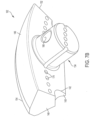
- each cutting segment 102 includes a coupling protrusion 134 extending from a body 138.
- the body 138 includes a lower surface 142, an outer wall 146, and a sloped inner wall 150.
- the outer wall 146 and the sloped inner wall 150 extend towards one another and meet at a peripheral edge or rim 154.
- An inner portion of the body 138 includes a lip or ledge 140 for engaging a shoulder 126 of the main support 94.
- the rim 154 includes bores 158 ( FIG. 7A ) extending into the body 138.
- the body 138 further includes a first end surface 148 and a second end surface 152.
- the cutting segments 102 are positioned around a perimeter of the main support 94 in an end-to-end relationship, such that a first end surface 148 of one segment 102 is positioned adjacent a second end surface 152 of an adjacent segment 102.
- the rims 154 of adjacent cutting segments 102 are aligned, thereby providing a substantially continuous cutting edge around the perimeter of the main support 94 (that is, the cutting edge is continuous except for gaps that may occur at the interfaces between adjacent cutting segments 102).
- each bore 158 receives a cutting button or cutting bit 162.
- the cutting bits 162 are positioned in a cutting plane 164 ( FIG. 4 ).
- the cutting bits 162 may be formed from a material having a high hardness (e.g., carbide).
- the rim 154 of each cutting segment 102 includes approximately fourteen bores 158 spaced at regular intervals; in other embodiments, the rim 154 may include fewer or more bores 158, and/or the bores 158 may be spaced irregularly along the rim 154.
- each bore 158 may be configured to receive a cutter button as described in U.S. Provisional Patent Application No. 62/342,254, filed on May 27, 2016 .
- Each cutting bit 162 may include a main portion (not shown) positioned in the bore 158 and an end portion 160 having a cutting formation (e.g., an edge or tip). The end portion protrudes from the bore 158 to engage the rock face.
- the cutting formations can be oriented at an angle relative to the axis of rotation of the cutting disc assembly 58.
- the rim 154 may include multiple types or sizes of bores configured to receive different types of cutting bits 162 or wear elements.
- the bores can be spaced apart or alternated, or alternatively placed on different surfaces of the cutting segment.
- the wear elements may be, for example, substantially similar to the wear buttons described in U.S. Provisional Patent Application No. 62/342,438, filed on May 27, 2016 .
- each cutting segment 102 is retained or secured to the main support 94 by the coupling protrusion 134.
- the coupling protrusion 134 is positioned in one of the cutter segment-receiving slots 122 ( FIG. 6 ) of the main support 94.
- the coupling protrusion134 is generally cylindrical.
- the coupling protrusion 134 extends from the lower surface 142 of the cutting segment 102, and an aperture 166 extends transversely through the coupling protrusion 134.
- the cutting segment 102 further includes a plurality of extraction holes 174 disposed on the lower surface 142 that are in operative communication with the bores 158.
- the extraction holes 174 are aligned with the bores 158 such that individual cutter bits 162 may be removed from the bores 158 using the extraction holes 174.
- the extraction holes 174 are also a smaller diameter than the bores 158 such that the cutter bits 162 are securely retained within the bores 158 without being over-inserted or compacted into the extraction holes 174.
- the extraction holes 174 may have a different diameter and/or the extraction holes 174 may be disposed at a different location on the cutting segment 102.
- the bore 158 may be blind bores without extraction holes.
- the bores 158 may be machined to a predetermined depth without being in communication with openings on an opposite side of the cutting segment.
- each cutting segment 102 is similar to the others.
- the cutting segments may be different.
- the cutting segments may be constructed from different materials, have different geometries, and/or may include different numbers and types of cutting buttons.
- the cutting segments may be secured to the main support 94 in another manner.
- the cutting bits 162 are spaced apart at regular intervals along the peripheral edge 154.
- a longitudinal axis B ( FIG. 9 ) of the cutter bits 162 is oriented at an angle relative to a plane defined by the end surface 110 of the main support 94.
- an angle C ( FIG. 9 ) of between approximately 0 degrees and approximately 90 degrees is formed between the end surface 110 and the longitudinal axis B of each cutting bits 162.
- the end surface 110 is substantially perpendicular to the longitudinal axis A of the cutter head 22.
- the cutting bits 162 are positioned such that the cutting edge is oriented in a direction that is radially outward from the longitudinal axis A of the cutting head 22.
- the coupling protrusion 134 is inserted into the cutter segment-receiving slot 122 and positioned such that the aperture 166 of the protrusion is aligned with the retention feature 130.
- the ledge 140 of the cutting segment 102 abuts the shoulder 126 of the main support 94, further ensuring that the protrusion 134 is properly aligned within the slot 122.
- the cutting segment 102 is secured by a retainer or fastener 182 (e.g., a pin, a bolt, a screw, etc.) through the bore of the retention feature 130 along axis D.
- the fastener extends through the aperture 166 of the cutting segment 102 and through a portion of the main support 94, thereby locking the cutting segment 102 to the main support 94 ( FIG. 12 ).
- the cutting segment 102 may be secured to the main support 94 in another manner.
- locking plates, clips, bolted connections, keyways, splines, extrusions, eccentric clamping, spring clamping, hydraulic clamping, interference fits, frictional fits, expansion interfaces, and/or tapered interfaces may be used.
- the retention feature 130 facilitates locking/attaching the cutting segment 102 to the main support 94, and can also provide additional advantages such as assisting in alignment of the cutting segment 102 and drawing the cutting segment 102 into abutment with the main support 94 to ensure a secure coupling.
- the coupling between the cutting segment 102 and the main support 94 enables and, in many cases, optimizes the load transfer to the main support 94 when the cutter bits 162 engage the rock face.
- the engagement between the shoulder 126 of the main support 94 and the cutting segment 102 assists in preventing rotation of the cutting segment 102 about the protrusion 134.
- This engagement also provides a larger load surface for distributing the load exerted on the cutting segment 102, which in turn minimizes the load that is transferred to the retainer 182 and enhances longevity of the cutting segments 102 and the retainer 182.
- the cutting disc assembly 58 is driven into engagement with a rock face.
- the exciter mass 70 is driven by the motor 78 to cause eccentric oscillation of the cutting head 22.
- the cutting head 22 may move about a wrist joint of the boom 18 ( FIG. 1 ), while the cutting disc assembly 58 is freely rotatable relative to the mining machine 10.
- the combination of free rotation of the cutting disc assembly 58 and oscillation enables efficient removal of rock from the rock face when forces are transmitted to the rock face by the cutter bits 162.
- the removable cutting segments 102 permit individual cutting segments 102 to be replaced when those segment become damaged or degraded rather than requiring replacement of an entire cutting member 96 or cutting disc 90.
- the cutting segments 102 can become 'modular' in that segments may be removed and replaced to customize the cutting disc assembly 58 to suit a particular application.
- cutting segments 102 of different materials or cutting segments 102 having different cutter bits 162 may be used in different applications (e.g., different rock face compositions, different environmental conditions, etc.).
- the effective cutting dimension of the cutting disc 90 can be modified without changing the main support 94, for example by replacing the cutting segments 102 with smaller or larger cutter segments on the main support 94, or by replacing the cutter segments including a peripheral edge having a different diameter.
- a method of servicing a cutting device for a mining machine including a plurality of cutting portions supported on a disc body, each cutting portion including a plurality of cutting bits positioned along a peripheral edge, the method comprising:
- the replacement cutting portion is a first replacement cutting portion and the planar surface is a first planar surface
- the method further comprises securing a second replacement cutting portion to the disc body such that the second replacement cutting portion is non-moveably coupled to the disc body, and wherein the second replacement cutting portion engages a second planar surface of the disc body that is oriented at an oblique angle with respect to the axis of rotation of the disc body.
- securing the second replacement cutting portion to the disc body includes positioning the second replacement cutting portion such that a peripheral edge of the second replacement cutting portion is positioned in an end-to-end relationship with the first replacement cutting portion.
- the method further comprises securing a third replacement cutting portion to the disc body such that the third replacement cutting portion is non-moveably coupled to the disc body, and wherein the third replacement cutting portion engages a third planar surface of the disc body that is oriented at an oblique angle with respect to the axis of rotation of the disc body.
- uncoupling one of the cutting portions from the disc body includes removing the one cutting portion from a position between adjacent cutting portions, and further comprising aligning a peripheral edge of the replacement cutting portion with peripheral edges of the adjacent cutting portions.
- uncoupling one of the cutting portions includes removing a protrusion of the one cutting portion from an associated one of a plurality of slots on the disc body.
- uncoupling one of the cutting portions includes removing a fastener from the protrusion and the disc body.
- securing the replacement cutting portion to the disc body includes forming a continuous peripheral edge with the adjacent cutting portions.
- securing the replacement cutting portion to the disc body includes forming a peripheral edge having a round profile.
- securing the replacement cutting portion to the disc body includes positioning the replacement cutting portion such that the peripheral edge of the replacement cutting portion is positioned in an end-to-end relationship with the adjacent cutting portions.
- the replacement cutting portion subtends an angle about an axis of rotation of the disc body, the angle being between approximately 30 degrees and approximately 120 degrees.
- a cutting device for engaging a rock face comprising:
- the disc body includes a plurality of slots, wherein each of the cutting portions includes a protrusion positioned within an associated one of the slots, each protrusion being secured within the associated one of the slots by a fastener extending through the protrusion and through at least a portion of the disc body.
- the cutting bits are positioned in a common cutting plane.
- each cutting portion includes a first end and a second end, wherein the cutting portions are positioned in an end-to-end relationship to form the cutting member, the first end of one cutting portion being positioned adjacent the second end of an adjacent cutting portion.
- a cutting device for engaging a rock face comprising:
- the disc body includes a plurality of slots, wherein each of the peripheral portions includes a protrusion positioned within an associated one of the slots.
- each protrusion is secured within the associated one of the slots by a fastener extending through the protrusion and through at least a portion of the disc body.
- peripheral portions are positioned around the axis of rotation and the cutting bits of the peripheral portions are positioned in a common cutting plane.
- the peripheral portions form a continuous cutting edge having a round profile extending around the axis of rotation.
- the peripheral portions are positioned in an end-to-end relationship around the axis of rotation, one end of one peripheral portion being positioned adjacent an end of an adjacent peripheral portion.
- each peripheral portion extends through an angle about the axis of rotation, the angle being between approximately 30 degrees and approximately 120 degrees.
- each peripheral portion includes a plurality of bores positioned on the peripheral edge, each of the cutting bits being positioned within an associated one of the bores.
- each peripheral portion further includes a plurality of extraction holes, each of the bores being in communication with an associated extraction hole to facilitate removal of the cutting bits from the peripheral portion.
- a cutting device for engaging a rock face comprising:
- each of the peripheral portions is independently secured to the disc body.
- the disc body includes a plurality of slots, wherein each of the peripheral portions includes a protrusion positioned within an associated one of the slots.
- each protrusion is secured within the associated one of the slots by a fastener extending through the protrusion and through at least a portion of the disc body.
- the peripheral portions are positioned around the axis of rotation and the peripheral edges form a round profile extending around the axis of rotation, the cutting bits of the peripheral portions positioned in a common cutting plane.
- each peripheral portion includes a first end and a second end, wherein the peripheral portions are positioned in an end-to-end relationship around the axis of rotation, the first end of one peripheral portion being positioned adjacent the second end of an adjacent peripheral portion.
- each peripheral portion extends through an angle about the axis of rotation, the angle being between approximately 30 degrees and approximately 120 degrees.
- each peripheral portion includes a plurality of bores positioned on the peripheral edge, each of the cutting bits being positioned within an associated one of the bore.
- each peripheral portion further includes a plurality of extraction holes, each of the bores being in communication with an associated extraction hole to facilitate removal of the cutting bits from the peripheral portion.
- a cutting head for engaging a rock wall comprising:
- each of the peripheral portions is independently secured to the disc body.
- the disc body includes a plurality of slots, wherein each of the peripheral portions includes a protrusion positioned within an associated one of the slots, each protrusion being secured within the associated one of the slots by a fastener extending through the protrusion and through at least a portion of the disc body.
- the peripheral portions are positioned around the axis of rotation and the peripheral edges form a round profile extending around the axis of rotation, the cutting bits of the peripheral portions positioned in a common cutting plane.
- each peripheral portion includes a first end and a second end, wherein the peripheral portions are positioned in an end-to-end relationship around the axis of rotation, the first end of one peripheral portion being positioned adjacent the second end of an adjacent peripheral portion.
- each peripheral portion extends through an angle about the axis of rotation, the angle being between approximately 30 degrees and approximately 120 degrees.
- a cutting device for engaging a rock face comprising:
- the disc body includes a plurality of slots, wherein each of the cutting portions includes a protrusion positioned within an associated one of the slots, each protrusion being secured within the associated one of the slots by a fastener extending through the protrusion and through at least a portion of the disc body.
- the cutting bits are positioned in a common cutting plane.
- each cutting portion includes a first end and a second end, wherein the cutting portions are positioned in an end-to-end relationship to form the cutting member, the first end of one cutting portion being positioned adjacent the second end of an adjacent cutting portion.
- a method of servicing a cutting device for a mining machine including a plurality of cutting portions supported on a disc body, each cutting portion including a plurality of cutting bits positioned along a peripheral edge, the method comprising:
Landscapes
- Engineering & Computer Science (AREA)
- Mining & Mineral Resources (AREA)
- Life Sciences & Earth Sciences (AREA)
- Geology (AREA)
- General Life Sciences & Earth Sciences (AREA)
- Geochemistry & Mineralogy (AREA)
- Mechanical Engineering (AREA)
- Environmental & Geological Engineering (AREA)
- General Engineering & Computer Science (AREA)
- Structural Engineering (AREA)
- Civil Engineering (AREA)
- Earth Drilling (AREA)
- Drilling And Exploitation, And Mining Machines And Methods (AREA)
- Fluid Mechanics (AREA)
- Physics & Mathematics (AREA)
- Processing Of Stones Or Stones Resemblance Materials (AREA)
- Finish Polishing, Edge Sharpening, And Grinding By Specific Grinding Devices (AREA)
- Shovels (AREA)
- Nonmetal Cutting Devices (AREA)
- Milling Processes (AREA)
- Polishing Bodies And Polishing Tools (AREA)
- Turning (AREA)
Applications Claiming Priority (5)
| Application Number | Priority Date | Filing Date | Title |
|---|---|---|---|
| US201662342254P | 2016-05-27 | 2016-05-27 | |
| US201662342438P | 2016-05-27 | 2016-05-27 | |
| US201762446799P | 2017-01-16 | 2017-01-16 | |
| PCT/US2017/034738 WO2017205777A1 (fr) | 2016-05-27 | 2017-05-26 | Tête de coupe comprenant un disque de coupe segmenté |
| EP17803688.5A EP3464821B1 (fr) | 2016-05-27 | 2017-05-26 | Tête de coupe comprenant un disque de coupe segmenté |
Related Parent Applications (1)
| Application Number | Title | Priority Date | Filing Date |
|---|---|---|---|
| EP17803688.5A Division EP3464821B1 (fr) | 2016-05-27 | 2017-05-26 | Tête de coupe comprenant un disque de coupe segmenté |
Publications (2)
| Publication Number | Publication Date |
|---|---|
| EP4421288A2 true EP4421288A2 (fr) | 2024-08-28 |
| EP4421288A3 EP4421288A3 (fr) | 2024-11-27 |
Family
ID=60411895
Family Applications (5)
| Application Number | Title | Priority Date | Filing Date |
|---|---|---|---|
| EP23173937.6A Pending EP4234882A3 (fr) | 2016-05-27 | 2017-05-26 | Dispositif de coupe à éléments d'usure |
| EP17803684.4A Active EP3463009B1 (fr) | 2016-05-27 | 2017-05-26 | Dispositif de coupe à élément de coupe conique |
| EP17803688.5A Active EP3464821B1 (fr) | 2016-05-27 | 2017-05-26 | Tête de coupe comprenant un disque de coupe segmenté |
| EP17803673.7A Active EP3463777B1 (fr) | 2016-05-27 | 2017-05-26 | Dispositif de coupe à éléments d'usure |
| EP24188575.5A Pending EP4421288A3 (fr) | 2016-05-27 | 2017-05-26 | Tête de coupe à disque de coupe segmenté |
Family Applications Before (4)
| Application Number | Title | Priority Date | Filing Date |
|---|---|---|---|
| EP23173937.6A Pending EP4234882A3 (fr) | 2016-05-27 | 2017-05-26 | Dispositif de coupe à éléments d'usure |
| EP17803684.4A Active EP3463009B1 (fr) | 2016-05-27 | 2017-05-26 | Dispositif de coupe à élément de coupe conique |
| EP17803688.5A Active EP3464821B1 (fr) | 2016-05-27 | 2017-05-26 | Tête de coupe comprenant un disque de coupe segmenté |
| EP17803673.7A Active EP3463777B1 (fr) | 2016-05-27 | 2017-05-26 | Dispositif de coupe à éléments d'usure |
Country Status (12)
| Country | Link |
|---|---|
| US (5) | US10626723B2 (fr) |
| EP (5) | EP4234882A3 (fr) |
| CN (4) | CN112879004B (fr) |
| AU (5) | AU2017271618B2 (fr) |
| CA (3) | CA3025635C (fr) |
| CL (3) | CL2018003370A1 (fr) |
| FI (3) | FI3463777T3 (fr) |
| PE (4) | PE20190079A1 (fr) |
| PL (3) | PL3463777T3 (fr) |
| RU (3) | RU2753564C2 (fr) |
| WO (3) | WO2017205777A1 (fr) |
| ZA (3) | ZA201807985B (fr) |
Families Citing this family (17)
| Publication number | Priority date | Publication date | Assignee | Title |
|---|---|---|---|---|
| BR112015005645B1 (pt) | 2012-09-14 | 2021-03-30 | Joy Global Underground Mining Llc | Cabeça de corte para máquina de mineração e máquina de mineração |
| AU2017271618B2 (en) | 2016-05-27 | 2023-01-05 | Joy Global Underground Mining Llc | Cutting device with wear elements |
| US11391149B2 (en) | 2016-08-19 | 2022-07-19 | Joy Global Underground Mining Llc | Mining machine with articulating boom and independent material handling system |
| RU2752854C2 (ru) | 2016-08-19 | 2021-08-11 | ДЖОЙ ГЛОБАЛ АНДЕРГРАУНД МАЙНИНГ ЭлЭлСи | Режущее устройство и опора для него |
| FI3516153T3 (fi) | 2016-09-23 | 2024-02-16 | Joy Global Underground Mining Llc | Kallionleikkuulaite |
| EP3392455B1 (fr) * | 2017-04-18 | 2023-09-27 | Sandvik Intellectual Property AB | Appareil de découpage |
| US11473273B2 (en) * | 2018-04-13 | 2022-10-18 | Caterpillar Inc. | Tool bit having a cylindrical profile and blade assembly |
| CN108590647B (zh) * | 2018-05-03 | 2019-10-15 | 罗春华 | 一种露天煤矿煤炭采挖装置 |
| EP3814608B1 (fr) * | 2018-07-25 | 2024-11-27 | Joy Global Underground Mining LLC | Ensemble de coupe de roches |
| CN108825227B (zh) * | 2018-08-08 | 2024-08-09 | 徐州徐工基础工程机械有限公司 | 掘进机切割装置和掘进机 |
| CN110857628B (zh) * | 2018-08-23 | 2025-11-25 | 上海创力集团股份有限公司 | 一种掘进机硬岩截割装置 |
| CN110424980B (zh) * | 2019-08-28 | 2020-10-20 | 盾构及掘进技术国家重点实验室 | 一种用于极硬岩开挖的先行引导式掘进机刀盘 |
| US11129238B1 (en) * | 2020-01-02 | 2021-09-21 | Gary D. Riha | Battery powered wireless controller system |
| JP7589980B2 (ja) * | 2020-12-22 | 2024-11-26 | 有限会社辰野目立加工所 | チップソー |
| CN114876486B (zh) * | 2022-05-20 | 2023-03-10 | 中国矿业大学 | 一种巷隧道掘进机器人及自动截割控制方法 |
| US20250188837A1 (en) * | 2023-12-06 | 2025-06-12 | Joy Global Underground Mining Llc | Cutting disc with removable cutting portions |
| CN118292899B (zh) * | 2024-03-14 | 2025-09-23 | 中国铁建重工集团股份有限公司 | 扩径式管道更新掘进机 |
Citations (2)
| Publication number | Priority date | Publication date | Assignee | Title |
|---|---|---|---|---|
| US7934776B2 (en) | 2007-08-31 | 2011-05-03 | Joy Mm Delaware, Inc. | Mining machine with driven disc cutters |
| US20140077578A1 (en) | 2012-09-14 | 2014-03-20 | Joy Mm Delaware, Inc. | Cutter head for mining machine |
Family Cites Families (97)
| Publication number | Priority date | Publication date | Assignee | Title |
|---|---|---|---|---|
| US2121202A (en) | 1935-03-19 | 1938-06-21 | Robert J Killgore | Rotary bit |
| US2763258A (en) | 1954-07-01 | 1956-09-18 | Hughes Blades Inc | Construction of circular saws |
| US3007049A (en) | 1959-03-12 | 1961-10-31 | Gen Dynamics Corp | Apparatus for generating electrostatic images |
| US3048160A (en) * | 1960-09-26 | 1962-08-07 | Trurun Inc | Attachment of cutting elements to wear resistant blades |
| US3411826A (en) * | 1966-05-26 | 1968-11-19 | Smith Ind International Inc | Tunnel boring machine |
| US3479122A (en) | 1967-04-05 | 1969-11-18 | Takaji Funahashi | Writing instrument |
| US3461983A (en) | 1967-06-28 | 1969-08-19 | Dresser Ind | Cutting tool having hard insert in hole surrounded by hard facing |
| US3442342A (en) | 1967-07-06 | 1969-05-06 | Hughes Tool Co | Specially shaped inserts for compact rock bits,and rolling cutters and rock bits using such inserts |
| US3536150A (en) * | 1968-09-05 | 1970-10-27 | Frank E Stebley | Rotary-percussion drill bit |
| US3641265A (en) | 1969-10-27 | 1972-02-08 | Arvin Ind Inc | Television recording system with alternate period inversion and automatic frequency control |
| US3633637A (en) * | 1970-07-06 | 1972-01-11 | Wallace Murray Corp | Segmental saw and method of making same |
| US3647265A (en) * | 1970-07-31 | 1972-03-07 | Greenside Machine Co Ltd | Cutting heads |
| SU443171A1 (ru) | 1973-01-22 | 1974-09-15 | Карагандинский политехнический институт | Рабочий орган горного комбайна |
| ZA743063B (en) * | 1974-05-14 | 1975-12-31 | Boart Hardmetals Ltd | Improvements in or relating to disc cutters for rock boring machines |
| ZA744897B (en) * | 1974-07-31 | 1976-05-26 | Board Hardmetal Proprietary Lt | Improvements in or relating to disc cutting units for use on rock boring machines |
| US3957307A (en) * | 1974-09-18 | 1976-05-18 | Olind Varda | Rough cutter mining tool |
| US3952815A (en) | 1975-03-24 | 1976-04-27 | Dresser Industries, Inc. | Land erosion protection on a rock cutter |
| US4109737A (en) | 1976-06-24 | 1978-08-29 | General Electric Company | Rotary drill bit |
| US4148368A (en) | 1976-09-27 | 1979-04-10 | Smith International, Inc. | Rock bit with wear resistant inserts |
| US4231438A (en) | 1978-10-10 | 1980-11-04 | Smith International, Inc. | Straight hole insert drill bit |
| US4202419A (en) | 1979-01-11 | 1980-05-13 | Dresser Industries, Inc. | Roller cutter with major and minor insert rows |
| SU937717A1 (ru) | 1980-07-11 | 1982-06-23 | Ленинградский Ордена Ленина И Ордена Трудового Красного Знамени Горный Институт Им.Г.В.Плеханова | Рабочий орган камнерезной машины |
| DE3039632C2 (de) | 1980-10-21 | 1982-12-16 | Christensen, Inc., 84115 Salt Lake City, Utah | Drehborhmeißel für Tiefbohrungen |
| DE3109367C2 (de) * | 1981-03-12 | 1983-11-17 | Hydroc Gesteinsbohrtechnik GmbH, 5960 Olpe | Bohrwerkzeug für Tieflochhämmer |
| US4442909A (en) * | 1981-09-21 | 1984-04-17 | Strata Bit Corporation | Drill bit |
| US4466498A (en) * | 1982-09-24 | 1984-08-21 | Bardwell Allen E | Detachable shoe plates for large diameter drill bits |
| US4499958A (en) * | 1983-04-29 | 1985-02-19 | Strata Bit Corporation | Drag blade bit with diamond cutting elements |
| US4527941A (en) | 1983-09-06 | 1985-07-09 | Vrp Partners, Ltd. | Expandable support structure usable as loading ramp |
| US4751972A (en) | 1986-03-13 | 1988-06-21 | Smith International, Inc. | Revolving cutters for rock bits |
| SU1416684A2 (ru) * | 1986-07-23 | 1988-08-15 | Подмосковный Научно-Исследовательский И Проектно-Конструкторский Угольный Институт | Исполнительный орган горной машины |
| US4755004A (en) | 1986-11-14 | 1988-07-05 | Palmquist Roger A | Rotary rocksaw device |
| US4753305A (en) | 1987-05-19 | 1988-06-28 | Dresser Industries, Inc. | Cutter mounting for drag bits |
| US4838366A (en) | 1988-08-30 | 1989-06-13 | Jones A Raymond | Drill bit |
| DE69009914T2 (de) | 1989-08-28 | 1994-10-13 | Atlas Copco Constr & Mining | Vorrichtung zur Positionierung eines Bohrmeissels. |
| CA2021187C (fr) * | 1990-06-20 | 1995-02-14 | F. Wayne Bales | Lame de scie non destructive pour materiau composite |
| NO301348B1 (no) | 1990-07-27 | 1997-10-13 | Mitsubishi Materials Corp | Boreverktöy |
| GB2253642B (en) | 1991-03-11 | 1995-08-09 | Dresser Ind | Method of manufacturing a rolling cone cutter |
| US5143163A (en) | 1991-08-29 | 1992-09-01 | Kennametal Inc. | Digging tooth |
| RU2018659C1 (ru) | 1991-09-11 | 1994-08-30 | Центральный научно-исследовательский и проектно-конструкторский институт проходческих машин и комплексов для угольной, горной промышленности и подземного строительства | Резец горной машины для разрушения преимущественно крепких пород |
| US5551760A (en) * | 1993-09-02 | 1996-09-03 | The Sollami Company | Tungsten carbide insert for a cutting tool |
| US5518443A (en) | 1994-05-13 | 1996-05-21 | Norton Company | Superabrasive tool |
| US5497843A (en) * | 1995-03-24 | 1996-03-12 | Central Mine Equipment | Hollow auger head assembly |
| US5722497A (en) | 1996-03-21 | 1998-03-03 | Dresser Industries, Inc. | Roller cone gage surface cutting elements with multiple ultra hard cutting surfaces |
| ATE218180T1 (de) | 1996-11-11 | 2002-06-15 | Hawera Probst Gmbh | Gesteinsbohrer |
| US5884979A (en) | 1997-04-17 | 1999-03-23 | Keystone Engineering & Manufacturing Corporation | Cutting bit holder and support surface |
| US6019434A (en) * | 1997-10-07 | 2000-02-01 | Fansteel Inc. | Point attack bit |
| SE513015C2 (sv) | 1997-11-19 | 2000-06-19 | Sandvik Ab | Rullborrkrona och stiftrulle för bergborrning |
| JPH11223090A (ja) * | 1998-02-05 | 1999-08-17 | Toshiba Tungaloy Co Ltd | 掘削用のカッタリング及び掘削用のディスクカッタ |
| EP0957232A1 (fr) * | 1998-05-13 | 1999-11-17 | BOART LONGYEAR GMBH & CO. KG HARTMETALLWERKZEUGFABRIK | Trépan à molettesavec des anneaux de coupe segmentés pour tunneliers |
| US6290008B1 (en) | 1998-12-07 | 2001-09-18 | Smith International, Inc. | Inserts for earth-boring bits |
| AUPP822499A0 (en) * | 1999-01-20 | 1999-02-11 | Terratec Asia Pacific Pty Ltd | Oscillating & nutating disc cutter |
| AUPP846599A0 (en) * | 1999-02-04 | 1999-02-25 | Sugden, David Burnet | Cutting device |
| US6367569B1 (en) | 2000-06-09 | 2002-04-09 | Baker Hughes Incorporated | Replaceable multiple TCI kerf ring |
| US6786557B2 (en) * | 2000-12-20 | 2004-09-07 | Kennametal Inc. | Protective wear sleeve having tapered lock and retainer |
| SE519284C2 (sv) * | 2001-06-21 | 2003-02-11 | Sandvik Ab | Verktygshuvud och verktyg |
| US6692083B2 (en) | 2002-06-14 | 2004-02-17 | Keystone Engineering & Manufacturing Corporation | Replaceable wear surface for bit support |
| US6766870B2 (en) | 2002-08-21 | 2004-07-27 | Baker Hughes Incorporated | Mechanically shaped hardfacing cutting/wear structures |
| EP1481782A1 (fr) | 2003-05-28 | 2004-12-01 | Alberto Filippini Fantoni | Outil de coupe pour des materiaux en pierre |
| CN2623865Y (zh) | 2003-06-25 | 2004-07-07 | 四川石油管理局 | 一种钢齿复合齿牙轮钻头 |
| US7401537B1 (en) | 2004-03-23 | 2008-07-22 | David Krauter | Cutter insert gum modification method and apparatus |
| US20090322143A1 (en) * | 2008-06-26 | 2009-12-31 | David Krauter | Cutter insert gum modification method and apparatus |
| SE525838C2 (sv) * | 2004-08-20 | 2005-05-10 | Sandvik Ab | Ett verktyg, en skärrulle och en stiftskiva för brytning av bergmaterial medelst underskärning |
| US7240746B2 (en) | 2004-09-23 | 2007-07-10 | Baker Hughes Incorporated | Bit gage hardfacing |
| US7389833B2 (en) * | 2005-06-10 | 2008-06-24 | Keystone Drill Services, Inc. | Multi-sectional percussive drill bit assembly |
| US8016056B2 (en) | 2005-07-01 | 2011-09-13 | Sandvik Intellectual Property Ab | Asymmetric graded composites for improved drill bits |
| JP4731308B2 (ja) | 2005-12-20 | 2011-07-20 | 株式会社奥村組 | トンネル掘削機のカッタ板 |
| US7338135B1 (en) | 2006-08-11 | 2008-03-04 | Hall David R | Holder for a degradation assembly |
| US7814998B2 (en) * | 2006-12-18 | 2010-10-19 | Baker Hughes Incorporated | Superabrasive cutting elements with enhanced durability and increased wear life, and drilling apparatus so equipped |
| DE102007013153B4 (de) | 2007-03-20 | 2019-01-24 | Kennametal Inc. | Werkzeug |
| AU2015203867B2 (en) | 2007-08-31 | 2017-01-05 | Joy Global Underground Mining Llc | Mining Machine with Driven Disc Cutters |
| RU2436952C1 (ru) | 2007-09-18 | 2011-12-20 | Буцирус Ойропе Гмбх | Шарошечный буровой инструмент или шарошечное долото |
| AU2008331975A1 (en) | 2007-12-05 | 2009-06-11 | Sandvik Intellectual Property Ab | Breaking or excavating tool with cemented tungsten carbide insert and ring, material removing machine incorporating such a tool and method of manufacturing such a tool |
| CN201198737Y (zh) * | 2008-04-02 | 2009-02-25 | 李婧 | 一种硬质合金楔凿钎头 |
| US7770664B2 (en) | 2008-05-29 | 2010-08-10 | Smith International, Inc. | Wear indicators for expandable earth boring apparatus |
| US8276577B2 (en) * | 2008-07-28 | 2012-10-02 | Aggregate Technologies, Inc. | Boom mounted saw |
| US20100181820A1 (en) * | 2009-01-22 | 2010-07-22 | Latham Winchester E | Wear insert and retainer |
| AT508232B1 (de) * | 2009-05-14 | 2011-05-15 | Sandvik Mining & Constr Oy | Schneidwerkzeug für eine bergbaumaschine |
| JP5058218B2 (ja) * | 2009-06-26 | 2012-10-24 | 日立造船株式会社 | 掘削機のビット交換装置 |
| DE102009049780B4 (de) | 2009-10-19 | 2016-02-18 | Betek Gmbh & Co. Kg | Meißel, insbesondere Rundschaftmeißel |
| CN101936169B (zh) * | 2010-08-24 | 2011-12-07 | 中铁隧道装备制造有限公司 | 软岩盾构机中具有小范围变径功能的切削装置 |
| CN201771431U (zh) * | 2010-09-17 | 2011-03-23 | 江汉石油钻头股份有限公司 | 一种用于牙轮钻头的凿形齿 |
| US8522899B2 (en) | 2010-10-01 | 2013-09-03 | Varel International, Ind., L.P. | Wear resistant material at the shirttail edge and leading edge of a rotary cone drill bit |
| AT510657B1 (de) | 2010-11-05 | 2013-04-15 | Sandvik Mining & Constr Oy | Streckenvortriebsmaschine |
| DE102011003714B8 (de) * | 2011-02-07 | 2012-08-30 | Mag Ias Gmbh | Bearbeitungseinrichtung zum Bearbeiten von Kurbelwellen sowie Bearbeitungssystem mit einer derartigen Bearbeitungseinrichtung |
| WO2013010063A1 (fr) | 2011-07-13 | 2013-01-17 | Varel International Ind., L.P. | Molettes en diamant polycristallin et trépans rotatifs mettant en œuvre des molettes en diamant polycristallin |
| US20130181501A1 (en) | 2012-01-17 | 2013-07-18 | David R. Hall | Pick with Threaded Shank |
| US8777326B2 (en) | 2012-01-23 | 2014-07-15 | David R. Hall | Pick with hardened core assembly |
| US9546520B2 (en) * | 2012-06-22 | 2017-01-17 | Baker Hughes Incorporated | Cutting element, tool and method of cutting within a borehole |
| CN102777173A (zh) | 2012-08-10 | 2012-11-14 | 江苏中机矿山设备有限公司 | 一种悬臂式电牵引采煤机 |
| CN203248080U (zh) * | 2013-02-28 | 2013-10-23 | 西南石油大学 | 一种混合钻头 |
| US9366088B2 (en) | 2013-03-08 | 2016-06-14 | Us Synthetic Corporation | Cutter assemblies, disc cutters, and related methods of manufacture |
| GB2514884A (en) * | 2013-03-15 | 2014-12-10 | Joy Mm Delaware Inc | Cutter head for longwall shearer |
| EP2811113A1 (fr) * | 2013-06-06 | 2014-12-10 | Caterpillar Global Mining Europe GmbH | Tête de coupe modulaire |
| DE102013107858B4 (de) | 2013-07-23 | 2023-03-16 | Kennametal Inc. | Werkzeug zum Dreh-Drehräumen von Werkstücken |
| SE1350983A1 (sv) * | 2013-08-27 | 2015-02-28 | Sandvik Intellectual Property | Verktyg och skär för skalfräsning |
| CN204782795U (zh) * | 2015-05-26 | 2015-11-18 | 株洲翔宇硬质合金有限公司 | 一种矿用牙轮钻头合金齿 |
| AU2017271618B2 (en) | 2016-05-27 | 2023-01-05 | Joy Global Underground Mining Llc | Cutting device with wear elements |
-
2017
- 2017-05-26 AU AU2017271618A patent/AU2017271618B2/en active Active
- 2017-05-26 PE PE2018003128A patent/PE20190079A1/es unknown
- 2017-05-26 FI FIEP17803673.7T patent/FI3463777T3/fi active
- 2017-05-26 AU AU2017269411A patent/AU2017269411B2/en active Active
- 2017-05-26 CA CA3025635A patent/CA3025635C/fr active Active
- 2017-05-26 EP EP23173937.6A patent/EP4234882A3/fr active Pending
- 2017-05-26 CN CN202110212303.XA patent/CN112879004B/zh active Active
- 2017-05-26 WO PCT/US2017/034738 patent/WO2017205777A1/fr not_active Ceased
- 2017-05-26 WO PCT/US2017/034729 patent/WO2017205773A1/fr not_active Ceased
- 2017-05-26 PL PL17803673.7T patent/PL3463777T3/pl unknown
- 2017-05-26 EP EP17803684.4A patent/EP3463009B1/fr active Active
- 2017-05-26 EP EP17803688.5A patent/EP3464821B1/fr active Active
- 2017-05-26 CN CN201780041478.0A patent/CN109414837B/zh active Active
- 2017-05-26 EP EP17803673.7A patent/EP3463777B1/fr active Active
- 2017-05-26 PL PL17803684.4T patent/PL3463009T3/pl unknown
- 2017-05-26 RU RU2018144221A patent/RU2753564C2/ru active
- 2017-05-26 CA CA3025632A patent/CA3025632C/fr active Active
- 2017-05-26 CA CA3025628A patent/CA3025628A1/fr active Pending
- 2017-05-26 WO PCT/US2017/034713 patent/WO2017205759A1/fr not_active Ceased
- 2017-05-26 PL PL17803688.5T patent/PL3464821T3/pl unknown
- 2017-05-26 RU RU2018146070A patent/RU2738928C2/ru active
- 2017-05-26 CN CN201780041462.XA patent/CN109415937B/zh active Active
- 2017-05-26 EP EP24188575.5A patent/EP4421288A3/fr active Pending
- 2017-05-26 US US15/606,745 patent/US10626723B2/en active Active
- 2017-05-26 FI FIEP17803688.5T patent/FI3464821T3/fi active
- 2017-05-26 AU AU2017269407A patent/AU2017269407B2/en active Active
- 2017-05-26 US US15/606,696 patent/US10808531B2/en active Active
- 2017-05-26 PE PE2018003126A patent/PE20190078A1/es unknown
- 2017-05-26 RU RU2018144352A patent/RU2741286C2/ru active
- 2017-05-26 US US15/606,651 patent/US10287881B2/en active Active
- 2017-05-26 PE PE2023002363A patent/PE20231956A1/es unknown
- 2017-05-26 CN CN201780041479.5A patent/CN109414135B/zh active Active
- 2017-05-26 FI FIEP17803684.4T patent/FI3463009T3/fi active
- 2017-05-26 PE PE2018003129A patent/PE20190061A1/es unknown
-
2018
- 2018-11-26 CL CL2018003370A patent/CL2018003370A1/es unknown
- 2018-11-26 ZA ZA2018/07985A patent/ZA201807985B/en unknown
- 2018-11-26 CL CL2018003369A patent/CL2018003369A1/es unknown
- 2018-11-26 ZA ZA2018/07986A patent/ZA201807986B/en unknown
- 2018-11-26 ZA ZA2018/07984A patent/ZA201807984B/en unknown
- 2018-11-27 CL CL2018003384A patent/CL2018003384A1/es unknown
-
2020
- 2020-03-16 US US16/820,224 patent/US10989050B2/en active Active
- 2020-10-16 US US17/072,351 patent/US11499426B2/en active Active
-
2023
- 2023-04-04 AU AU2023202048A patent/AU2023202048B2/en active Active
- 2023-07-20 AU AU2023206186A patent/AU2023206186B2/en active Active
Patent Citations (2)
| Publication number | Priority date | Publication date | Assignee | Title |
|---|---|---|---|---|
| US7934776B2 (en) | 2007-08-31 | 2011-05-03 | Joy Mm Delaware, Inc. | Mining machine with driven disc cutters |
| US20140077578A1 (en) | 2012-09-14 | 2014-03-20 | Joy Mm Delaware, Inc. | Cutter head for mining machine |
Also Published As
Similar Documents
| Publication | Publication Date | Title |
|---|---|---|
| US10989050B2 (en) | Cutting head having segmented cutting disc | |
| CN113027448B (zh) | 具有多个切削头的采矿机械 | |
| CN102132007A (zh) | 具有将水注射到切削刀头柄部的切削刀具 | |
| EP3538743B1 (fr) | Unité de coupe à rouleaux pour machine à entailler | |
| BR112018074508B1 (pt) | Dispositivo de corte e cabeça de corte e manutenção de um dispositivo de corte para uma máquina de mineração | |
| WO2022243453A1 (fr) | Dispositif de coupe à disque et module à changement rapide | |
| CA3012831C (fr) | Machine d'extraction ayant de multiples tetes de coupe |
Legal Events
| Date | Code | Title | Description |
|---|---|---|---|
| PUAI | Public reference made under article 153(3) epc to a published international application that has entered the european phase |
Free format text: ORIGINAL CODE: 0009012 |
|
| STAA | Information on the status of an ep patent application or granted ep patent |
Free format text: STATUS: THE APPLICATION HAS BEEN PUBLISHED |
|
| AC | Divisional application: reference to earlier application |
Ref document number: 3464821 Country of ref document: EP Kind code of ref document: P |
|
| AK | Designated contracting states |
Kind code of ref document: A2 Designated state(s): AL AT BE BG CH CY CZ DE DK EE ES FI FR GB GR HR HU IE IS IT LI LT LU LV MC MK MT NL NO PL PT RO RS SE SI SK SM TR |
|
| REG | Reference to a national code |
Ref country code: DE Ref legal event code: R079 Free format text: PREVIOUS MAIN CLASS: E21C0025180000 Ipc: B28D0001120000 |
|
| PUAL | Search report despatched |
Free format text: ORIGINAL CODE: 0009013 |
|
| AK | Designated contracting states |
Kind code of ref document: A3 Designated state(s): AL AT BE BG CH CY CZ DE DK EE ES FI FR GB GR HR HU IE IS IT LI LT LU LV MC MK MT NL NO PL PT RO RS SE SI SK SM TR |
|
| RIC1 | Information provided on ipc code assigned before grant |
Ipc: E21D 9/10 20060101ALI20241022BHEP Ipc: E21D 9/11 20060101ALI20241022BHEP Ipc: E21C 25/16 20060101ALI20241022BHEP Ipc: E21C 27/24 20060101ALI20241022BHEP Ipc: E21C 25/00 20060101ALI20241022BHEP Ipc: E21C 25/18 20060101ALI20241022BHEP Ipc: E21C 35/00 20060101ALI20241022BHEP Ipc: E21C 25/06 20060101ALI20241022BHEP Ipc: E21C 35/24 20060101ALI20241022BHEP Ipc: B28D 1/12 20060101AFI20241022BHEP |
|
| STAA | Information on the status of an ep patent application or granted ep patent |
Free format text: STATUS: REQUEST FOR EXAMINATION WAS MADE |
|
| 17P | Request for examination filed |
Effective date: 20250526 |
|
| STAA | Information on the status of an ep patent application or granted ep patent |
Free format text: STATUS: EXAMINATION IS IN PROGRESS |
|
| 17Q | First examination report despatched |
Effective date: 20260130 |