EP4421832A1 - Transformatoranordnung - Google Patents
Transformatoranordnung Download PDFInfo
- Publication number
- EP4421832A1 EP4421832A1 EP23157823.8A EP23157823A EP4421832A1 EP 4421832 A1 EP4421832 A1 EP 4421832A1 EP 23157823 A EP23157823 A EP 23157823A EP 4421832 A1 EP4421832 A1 EP 4421832A1
- Authority
- EP
- European Patent Office
- Prior art keywords
- air
- airflow
- multiplier
- redistribution device
- axis
- Prior art date
- Legal status (The legal status is an assumption and is not a legal conclusion. Google has not performed a legal analysis and makes no representation as to the accuracy of the status listed.)
- Pending
Links
Images


Classifications
-
- H—ELECTRICITY
- H05—ELECTRIC TECHNIQUES NOT OTHERWISE PROVIDED FOR
- H05K—PRINTED CIRCUITS; CASINGS OR CONSTRUCTIONAL DETAILS OF ELECTRIC APPARATUS; MANUFACTURE OF ASSEMBLAGES OF ELECTRICAL COMPONENTS
- H05K7/00—Constructional details common to different types of electric apparatus
- H05K7/20—Modifications to facilitate cooling, ventilating, or heating
- H05K7/20009—Modifications to facilitate cooling, ventilating, or heating using a gaseous coolant in electronic enclosures
- H05K7/20136—Forced ventilation, e.g. by fans
- H05K7/20172—Fan mounting or fan specifications
-
- H—ELECTRICITY
- H01—ELECTRIC ELEMENTS
- H01F—MAGNETS; INDUCTANCES; TRANSFORMERS; SELECTION OF MATERIALS FOR THEIR MAGNETIC PROPERTIES
- H01F27/00—Details of transformers or inductances, in general
- H01F27/02—Casings
- H01F27/025—Constructional details relating to cooling
-
- F—MECHANICAL ENGINEERING; LIGHTING; HEATING; WEAPONS; BLASTING
- F04—POSITIVE - DISPLACEMENT MACHINES FOR LIQUIDS; PUMPS FOR LIQUIDS OR ELASTIC FLUIDS
- F04F—PUMPING OF FLUID BY DIRECT CONTACT OF ANOTHER FLUID OR BY USING INERTIA OF FLUID TO BE PUMPED; SIPHONS
- F04F5/00—Jet pumps, i.e. devices in which flow is induced by pressure drop caused by velocity of another fluid flow
- F04F5/14—Jet pumps, i.e. devices in which flow is induced by pressure drop caused by velocity of another fluid flow the inducing fluid being elastic fluid
- F04F5/16—Jet pumps, i.e. devices in which flow is induced by pressure drop caused by velocity of another fluid flow the inducing fluid being elastic fluid displacing elastic fluids
-
- H—ELECTRICITY
- H01—ELECTRIC ELEMENTS
- H01F—MAGNETS; INDUCTANCES; TRANSFORMERS; SELECTION OF MATERIALS FOR THEIR MAGNETIC PROPERTIES
- H01F27/00—Details of transformers or inductances, in general
- H01F27/08—Cooling; Ventilating
- H01F27/10—Liquid cooling
- H01F27/12—Oil cooling
Definitions
- the present disclosure relates to an airflow generator, and to a transformer assembly comprising such an airflow generator for cooling of a heat exchanger provided externally of the transformer for cooling of the transformer.
- a power transformer is equipment used in an electric grid of a power system. Power transformers transform voltage and current in order to transport and distribute electric energy. Power transformers involve high currents; therefore, production of heat is inevitable. This heat propagates in oil inside a transformer tank. It is important to release this heat to the surroundings for the normal operation of transformers. An important part of oil-cooling is carried out by placing external devices by the transformer, such as radiators, cooler banks etc., through which the transformer oil is circulated and get cooled.
- State-of-the art air-cooling for a transformer is performed using conventional fans, i.e., bladed fans, or using natural convection.
- the state-of-the-art cooling systems using bladed fans typically produce high noise, have complex structure, are heavy, and are difficult to maintain. For high-power transformers, natural convection is not enough to cool the transformer, and therefore, forced cooling is needed.
- External transformer cooling generally uses a one or more radiators external to the transformer, said radiators allowing oil to circulate from the transformer and out to the radiators, where heat is dissipated from the oil to surrounding ambient air.
- the cooling process typically uses natural convection or forced convection to move ambient air past the radiator.
- This disclosure concerns cooling systems using forced convection. Forced convection is typically achieved using one or more large fans blowing air through or onto the radiator(s). Cooling efficiency is dependent on airflow rate and consequently on the power consumption of the fans.
- an object of the present disclosure is to provide a compact and power-efficient airflow generator cooling arrangement for a transformer.
- the transformer arrangement comprises an airflow generator and a transformer provided with an oil-to-air heat exchanger.
- the airflow generator is configured to discharge air towards the oil-to-air heat exchanger and comprises an electrically powered ducted fan provided with an inlet and an outlet, a fluid conduit; an air multiplier for discharging air along a first axis, the air multiplier comprising an inlet and an outlet; and an airflow redistribution device that is axially displaced from the air multiplier along the first axis, downstream of the air multiplier.
- the air multiplier comprises an inlet and an outlet, the fluid conduit fluidly connects the outlet of the ducted fan to the inlet of the air multiplier, and the airflow redistribution device is configured to redirect airflow from regions of higher speed airflow discharged from the air multiplier to regions of lower speed airflow discharged from the air multiplier, thereby promoting a more even distribution of airflow speeds downstream of the airflow redistribution device.
- the herein disclosed airflow generator comprising the air flow redistribution device, provides a more even distribution of airflow rates closer to the airflow generator, thereby allowing the airflow generator to be positioned closer to an object to be cooled by the airflow. This enables a reduction of the size of a product incorporating the airflow generator for cooling of the product.
- the fan provides an airflow into the air multiplier.
- the ducted nature of the fan enables it to efficiently pressurize the fluid conduit.
- By providing the airflow generator with an air multiplier a much larger amount of air than the amount of air supplied by the fan, is discharged towards the oil-to-air heat exchanger. This reduces power consumption as compared to use of conventional fans directly blowing air against the oil-to-air heat exchanger.
- noise emitted from the fan and air multiplier combination may be lower than a corresponding noise level emitted from a fan achieving the same airflow towards the heat exchanger.
- Air multipliers are often configured as rings with a central opening through which air is moved along by air discharged from the air multiplier.
- the flow velocity of air flowing through the ring is higher closer to the ring and lower further from the ring.
- the generated air flow from the air multiplier can have an approximately cylindrical shape with low speed in the core of the cylinder and much higher speeds at the edges of the cylinder.
- a cooling pattern delivered by the air flow is far from being uniform, such that some areas of the heat exchanger have a higher heat transfer coefficient whereas other areas, receiving an air with lower velocity, have a lower heat transfer coefficient and thus not perform sufficient cooling.
- the airflow redistribution device may comprise various shapes and configurations that facilitate redirecting the airflow from regions of higher speed airflow discharged from the air multiplier to regions of lower speed airflow discharged from the air multiplier.
- the airflow redistribution device may comprise a ring-shaped profile extending around the first axis.
- the airflow redistribution device may comprise a plurality of differently sized ring-shaped profiles extending around the first axis.
- Each ring-shaped profile may have a diameter which is gradually decreasing in a discharge direction along the first axis.
- the airflow redistribution device may comprise an array of air deflector members distributed transversely to the first axis such that the air deflector members jointly define air passages between the air deflector members.
- the air deflector members may be configured such that a plurality of the air passages extend at an angle to the first axis A in the range of 1-45 degrees. Such a configuration of the air passages facilitates redirecting the airflow from regions of higher speed airflow discharged from the air multiplier to regions of lower speed airflow discharged from the air multiplier.
- the air deflector members are rectangular-shaped plates.
- the air flow redistribution device that is configured to redirect airflow from regions of higher speed airflow discharged from the air multiplier to regions of lower speed airflow discharged from the air multiplier, the air flow discharged from the air multiplier is homogenized and becomes sufficiently wider to thereby cover a larger surface of the heat exchanger, as compared to a transformer arrangement without the air flow redistribution device.
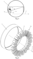
- Fig. 1 shows a prior art airflow generator comprising an electrically powered ducted fan 2 provided with an inlet 3 and an outlet 4.
- the airflow generator 1 further comprises a fluid conduit 5 and an air multiplier 7a for discharging air along a first axis A.
- the air multiplier 7a comprises an inlet 8 and an outlet 9.
- the fluid conduit 5 fluidly connects the outlet 4 of the ducted fan 2 to the inlets 8 of the air multiplier 7a.
- Air multiplier is used in the prior art and thus should be known to the skilled person. Air multipliers are nozzles typically used in bladeless fans. Herein, the term air multiplier may to refer to any type of air discharge device/nozzle designed to discharge air through an outlet, typically in the form of one or more elongate slits, such that air around the discharge device is brought along by the air discharged from the outlet at a rate of at least 5-15 times the amount of air discharged by the outlet.
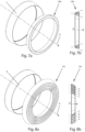
- Coand effect air flow multiplier Such air discharge devices can vary greatly in design but are often shaped like an extruded hollow profile, an example of which is shown in Fig. 5 , although any other suitable shape is possible.
- the profile usually has an elongate cross-sectional shape, and the outlet is typically configured to discharge air in a direction along a first axis extending along the length of the elongate cross-sectional shape, as shown in Fig. 5 .
- the profile may have an aerodynamic foil shape.
- the outlet may be provided anywhere suitable along the length of the cross-sectional shape of the profile, such as at a leading portion of the profile (facing incoming ambient air as in Fig.
- the profile may be straight but is typically bent to form a ring circumscribing an inner cross-sectional area of the air multiplier.
- FIG. 2 the airflow generator 1, also shown in Fig. 1 , is shown without the ducted fan 2 and without the fluid conduit 5.
- the fan 2 provides an airflow into the air multiplier 7a.
- the ducted nature of the fan 2 enables it to efficiently pressurize the fluid conduit 5.
- the airflow generator 1 By providing the airflow generator 1 with an air multiplier 7a, a much larger amount of air than the amount of air supplied by the fan 2, is discharged towards the oil-to-air heat exchanger (not shown in Figs. 1 and 2 ).
- the airflow generator 1 may thus be able to output an airflow of ten to fifteen times the airflow produced by the fan 2. This reduces power consumption as compared to use of conventional fans directly blowing air against an object to be cooled, such as an oil-to-air heat exchanger provided on a transformer.
- Such air multipliers 7a are typically configured as rings with a central opening through which air is moved along by air discharged from the air multiplier along the first axis A.
- the flow velocity of air flowing through the ring is higher closer to the ring and lower further from the ring, as indicated by the broken-line arrows in Fig. 1 whose lengths schematically indicate a speed of local airflow.
- the present disclosure provides a transformer arrangement comprising, in addition to the air multiplier, an airflow redistribution device axially displaced from the air multiplier along the first axis A, downstream of the air multiplier.
- the airflow redistribution device is configured to redirect airflow from regions of higher speed airflow discharged from the air multiplier to regions of lower speed airflow discharged from the air multiplier, thereby promoting a more even distribution of airflow speeds downstream of the airflow redistribution device.
- FIG. 3 schematically illustrates, for comparison purposes, a transformer arrangement 12 comprising an air flow generator 1, corresponding to air flow generator 1 of Figs. 1 and 2 described above, the transformer arrangement 12 being without an air flow redistribution device.
- the transformer arrangement 12 further comprises a transformer 10 provided with an oil-to-air external heat exchanger 11.
- the airflow generator 1 is configured to discharge air towards the oil-to-air heat exchanger 11.
- the oil-to-air external heat exchanger 11 is external in the sense that it is mounted externally on the transformer 10, thereby being able to radiate and conduct heat to surrounding air.
- oil from inside the transformer 10 is pumped through the oil-to-air heat exchanger 11, wherein the oil transports heat generated within the transformer 10 out to the heat exchanger 11, such that the airflow from the airflow generator 1 cools the heat exchanger 11.
- Fig. 3 illustrates that the flow velocity of air flowing through the airflow generator 1 is higher closer to the walls of the airflow generator 1 and lower further from the airflow generator 1, as indicated by the broken-line arrows in Fig. 3 , where the length of the arrows schematically indicates a speed of local airflow.
- Fig. 3 shows regions of higher speed airflow that are closer to the walls of the air multiplier 7, and regions of lower speed airflow that are further away from the walls of the air multiplier 7 and are closer to the first axis (A).
- Fig. 4 schematically illustrates a transformer arrangement 12 proposed by the present disclosure.
- the transformer arrangement 12 comprises an airflow generator 1 and also includes an air flow redistribution device 14 in accordance with the present disclosure.
- the transformer arrangement 12 of Fig. 4 comprises a transformer 10 provided with an oil-to-air external heat exchanger 11.
- the airflow generator 1 of Fig. 4 is configured to discharge air towards the oil-to-air heat exchanger 11.
- the air flow redistribution device 14 redirects the airflow from regions of higher speed airflow discharged from the air multiplier 7 to regions of lower speed airflow discharged from the air multiplier 7, thereby promoting a more even distribution of airflow speeds downstream of the airflow redistribution device 14.
- the airflow, passed through the air multiplier 7 and then through the air flow redistribution device 14 becomes more uniform due to the configuration of the air flow redistribution device 14 that causes more even distribution of airflow speeds downstream of the airflow redistribution device 14. In this way, in contrast to existing arrangements as shown in Figs.
- the term "substantially” is defined as being largely but not necessarily wholly what is specified, e.g., within 10% or within 1% or within 0.1% of what is specified, as understood by a person of ordinary skill in the art.
- substantially perpendicular includes perpendicular
- substantially coinciding includes coinciding
- the transformer arrangement 12 in accordance with the present disclosure allows having a reduced distance, d4, between the airflow generator 1 and the transformer 10 that allows the heat exchanger to receive a more evenly distributed air flow.
- the air flow generator 1 can be positioned closer to an object to be cooled by the airflow generated by the air flow generator 1, such as the oil-to-air external heat exchanger 11. This allows a reduction in a size of the transformer assembly 12.
- the air flow generator 1 and the oil-to-air external heat exchanger 11 may be positioned in a more compact arrangement of the components of the transformer assembly 12.
- the air flow redistribution device 14 may have a central axis that substantially coincides with the first axis A.
- the airflow redistribution device 14 may comprise a ring-shaped profile extending around the first axis A.
- the ring-shaped profile covers any ring shape including circular rings and non-circular rings, such as rings comprising straight portions or a combination or curved and straight portions.
- the air flow redistribution device 14 may have a square, pentagonal, hexagonal, or any other n-gonal cross-section.
- the air flow redistribution device 14 may form an open loop or a closed loop. A closed-loop configuration makes the device robust.
- the ring-shaped profile of the airflow redistribution device 14 may be formed by a single element or by multiple elements arranged to redistribute the air flow to equalize airflow speeds.
- An airflow redistribution device in accordance with the present disclosure can have various designs.
- Figs. 6 , 7a, 7b, 8a , 8b , 9a, and 9b illustrate non-limiting examples of the airflow redistribution device 14 in accordance with the present disclosure.
- the airflow redistribution device 14 redirects airflow from regions of higher speed airflow discharged from the air multiplier to regions of lower speed airflow discharged from the air multiplier, thereby promoting a more even distribution of airflow speeds downstream of the airflow redistribution device 14.
- Fig. 6 illustrates the air multiplier 7 and an example of an airflow redistribution device 14a that comprises an array of air deflector members 15 distributed transversely to the first axis A such that the air deflector members 15 jointly define air passages between the air deflector members 15.
- the air deflector members 15 are configured such that a plurality of the air passages extend at an angle to the first axis A in the range of from 1 to 45 degrees.
- the air deflector members 15 are distributed along the circumference of the airflow redistribution device 14a.
- the air deflector members 15 are rectangular-shaped plates. Plates are arranged in a stacked configuration such that each stack comprises a plurality of plates radially distributed with respect to the first axis A, wherein plates in a stack are disposed at an angle relative to plates in an adjacent stack. Five air deflector members in each stack are shown as an example only, since another suitable number of air deflector members may be arranged in a configuration as shown in Fig. 6 . Also, the air deflector members 15 can have other shapes, including triangular, square, pentagonal, or another n-gonal shape.
- the airflow redistribution device 14a shown in Fig. 6 comprises support means (not shown) configured to carry the air deflector members 15.
- Fig. 7a illustrates the air multiplier 7 and an example of an airflow redistribution device 14b that comprises a single ring-shaped profile extending around the first axis A.
- the airflow redistribution device 14b has a wedge-shaped cross-sectional profile, which in this embodiment is hollow, but in other embodiments could be solid. A leading portion of the wedge-shaped profile faces incoming air.
- the airflow discharged from the air multiplier 7 encounters the leading portion of the profile of the airflow redistribution device 14b and is diverted from its original direction by the curved walls of the airflow redistribution device 14b. This facilitates distribution of the airflow discharged from the air multiplier 7.
- the surfaces of the wedge-shaped profile are adapted to the indented air redistribution directions on a case-by-case basis.
- the airflow redistribution device 14b having a hollow profile, is more lightweight than a solid structure, which is advantageous for mounting and maintenance of a transformer arrangement. Also, manufacturing costs of the air flow generator 1 may be reduced due to a relatively simple configuration of the airflow redistribution device 14b.
- Figs. 8a and 8b illustrate the air multiplier 7 and another example of an airflow redistribution device 14c that comprises a plurality of differently sized ring-shaped profiles extending around the first axis A.
- the airflow redistribution device 14c has five differently sized concentric rings in the form of hollow truncated cones. Each ring thus has a straight cross-sectional profile provided at an angle to the first axis A adapted to direct incoming air radially inwards with respect to the first axis A.
- the cross-sectional profiles are illustrated in Fig. 8b , along with broken-line arrows schematically illustrating redirection of incoming air.
- the rings may be non-circular, yet using the same type of cross-sectional profile to redirect air.
- Fig. 9a illustrates an example of a configuration of an air flow redistribution device 14d having a square ring shape with rounded corners.
- the cross-sectional profile of the air flow redistribution device 14d is wedge-shaped similar to the embodiment of Figs. 7a-7b .
Landscapes
- Engineering & Computer Science (AREA)
- Power Engineering (AREA)
- Microelectronics & Electronic Packaging (AREA)
- Physics & Mathematics (AREA)
- Thermal Sciences (AREA)
- Fluid Mechanics (AREA)
- Mechanical Engineering (AREA)
- General Engineering & Computer Science (AREA)
- Transformer Cooling (AREA)
- Heat-Exchange Devices With Radiators And Conduit Assemblies (AREA)
- Cooling Or The Like Of Electrical Apparatus (AREA)
Priority Applications (4)
| Application Number | Priority Date | Filing Date | Title |
|---|---|---|---|
| EP23157823.8A EP4421832A1 (de) | 2023-02-21 | 2023-02-21 | Transformatoranordnung |
| CN202480013524.6A CN120731467A (zh) | 2023-02-21 | 2024-02-19 | 变压器装置 |
| PCT/EP2024/054157 WO2024175542A1 (en) | 2023-02-21 | 2024-02-19 | A transformer arrangement |
| US19/157,722 US20260113868A1 (en) | 2023-02-21 | 2024-02-19 | A transformer arrangement |
Applications Claiming Priority (1)
| Application Number | Priority Date | Filing Date | Title |
|---|---|---|---|
| EP23157823.8A EP4421832A1 (de) | 2023-02-21 | 2023-02-21 | Transformatoranordnung |
Publications (1)
| Publication Number | Publication Date |
|---|---|
| EP4421832A1 true EP4421832A1 (de) | 2024-08-28 |
Family
ID=85321243
Family Applications (1)
| Application Number | Title | Priority Date | Filing Date |
|---|---|---|---|
| EP23157823.8A Pending EP4421832A1 (de) | 2023-02-21 | 2023-02-21 | Transformatoranordnung |
Country Status (4)
| Country | Link |
|---|---|
| US (1) | US20260113868A1 (de) |
| EP (1) | EP4421832A1 (de) |
| CN (1) | CN120731467A (de) |
| WO (1) | WO2024175542A1 (de) |
Citations (4)
| Publication number | Priority date | Publication date | Assignee | Title |
|---|---|---|---|---|
| US20010032718A1 (en) * | 2000-02-24 | 2001-10-25 | Unifin International, Inc. | System and method for cooling transformers |
| US8461953B1 (en) * | 2009-08-18 | 2013-06-11 | Marvin W. Ward | System, method and apparatus for transformer cooling |
| US20170057621A1 (en) * | 2015-09-02 | 2017-03-02 | Jetoptera, Inc. | Fluidic propulsive system and thrust and lift generator for aerial vehicles |
| US20190280562A1 (en) * | 2016-01-20 | 2019-09-12 | Soliton Holdings Corporation, Delaware Corporation | Generalized Jet-Effect and Generalized Generator |
Family Cites Families (3)
| Publication number | Priority date | Publication date | Assignee | Title |
|---|---|---|---|---|
| CN110534298B (zh) * | 2018-05-25 | 2022-12-16 | 日立能源瑞士股份公司 | 用于变压器的冷却系统 |
| CN214203391U (zh) * | 2020-11-26 | 2021-09-14 | Abb电网瑞士股份公司 | 具有气流重定向器的变压器 |
| CN215680332U (zh) * | 2021-07-05 | 2022-01-28 | 洛阳星牛变压器有限公司 | 一种变压器用的循环油冷装置 |
-
2023
- 2023-02-21 EP EP23157823.8A patent/EP4421832A1/de active Pending
-
2024
- 2024-02-19 WO PCT/EP2024/054157 patent/WO2024175542A1/en not_active Ceased
- 2024-02-19 US US19/157,722 patent/US20260113868A1/en active Pending
- 2024-02-19 CN CN202480013524.6A patent/CN120731467A/zh active Pending
Patent Citations (4)
| Publication number | Priority date | Publication date | Assignee | Title |
|---|---|---|---|---|
| US20010032718A1 (en) * | 2000-02-24 | 2001-10-25 | Unifin International, Inc. | System and method for cooling transformers |
| US8461953B1 (en) * | 2009-08-18 | 2013-06-11 | Marvin W. Ward | System, method and apparatus for transformer cooling |
| US20170057621A1 (en) * | 2015-09-02 | 2017-03-02 | Jetoptera, Inc. | Fluidic propulsive system and thrust and lift generator for aerial vehicles |
| US20190280562A1 (en) * | 2016-01-20 | 2019-09-12 | Soliton Holdings Corporation, Delaware Corporation | Generalized Jet-Effect and Generalized Generator |
Also Published As
| Publication number | Publication date |
|---|---|
| CN120731467A (zh) | 2025-09-30 |
| WO2024175542A1 (en) | 2024-08-29 |
| US20260113868A1 (en) | 2026-04-23 |
Similar Documents
| Publication | Publication Date | Title |
|---|---|---|
| US9991759B2 (en) | Multi-directional air cooling of a motor using radially mounted fan and axial/circumferential cooling fins | |
| US9253928B2 (en) | Cooling module with parallel blowers | |
| US20220082278A1 (en) | Air curtain containment system and assembly for data centers | |
| US8767400B2 (en) | Cooling module with parallel blowers | |
| EP2681847B1 (de) | Kühlsystem und verfahren zur kühlung einer funkeinheit | |
| WO2020048072A1 (zh) | 电机及风力发电机组 | |
| CA3116099C (en) | Transformer cooling system and transformer installation | |
| EP2546515B1 (de) | Windturbinen-Kühlanordnung | |
| US20150211490A1 (en) | Cooling arrangement | |
| CN1830695A (zh) | 机车动态制动栅格单元的配置 | |
| EP4415006B1 (de) | Luftstromerzeuger | |
| EP4421832A1 (de) | Transformatoranordnung | |
| CN114190107A (zh) | 用于变压器的冷却装置 | |
| EP2814144A1 (de) | Luft-Luft-Wärmetauscher | |
| US20260122835A1 (en) | An airflow generator | |
| WO2018162914A2 (en) | Enhanced cooling for generator | |
| US20220159880A1 (en) | Inverter and heat radiation structure thereof | |
| EP4415007A1 (de) | Luftstromerzeuger | |
| EP4549745B1 (de) | Luftstromerzeuger | |
| US10986750B2 (en) | Heat exchange device in directed flow system | |
| EP3355024A1 (de) | Luftgekühlter kondensator mit luftstromdiffusor | |
| CN210460966U (zh) | 一种风力发电组散热结构 | |
| CN207257363U (zh) | 用于电动车辆的动力系统和电动车辆 | |
| DE102023128967A1 (de) | Elektrische Antriebsvorrichtung und ein Verfahren zur Kühlung der elektrischen Antriebsvorrichtung | |
| CN119944159A (zh) | 分流匀风系统、储能风冷体系和储能风冷集装箱 |
Legal Events
| Date | Code | Title | Description |
|---|---|---|---|
| PUAI | Public reference made under article 153(3) epc to a published international application that has entered the european phase |
Free format text: ORIGINAL CODE: 0009012 |
|
| STAA | Information on the status of an ep patent application or granted ep patent |
Free format text: STATUS: THE APPLICATION HAS BEEN PUBLISHED |
|
| AK | Designated contracting states |
Kind code of ref document: A1 Designated state(s): AL AT BE BG CH CY CZ DE DK EE ES FI FR GB GR HR HU IE IS IT LI LT LU LV MC ME MK MT NL NO PL PT RO RS SE SI SK SM TR |
|
| STAA | Information on the status of an ep patent application or granted ep patent |
Free format text: STATUS: REQUEST FOR EXAMINATION WAS MADE |
|
| 17P | Request for examination filed |
Effective date: 20250225 |
|
| RIN1 | Information on inventor provided before grant (corrected) |
Inventor name: HOSAIN, LOKMAN Inventor name: SAND, ULF Inventor name: BEL FDHILA, REBEI |