EP4421900A1 - Électrode négative pour batterie secondaire au lithium, et dispositif d'alignement magnétique pour la même électrode négative - Google Patents
Électrode négative pour batterie secondaire au lithium, et dispositif d'alignement magnétique pour la même électrode négative Download PDFInfo
- Publication number
- EP4421900A1 EP4421900A1 EP23877545.6A EP23877545A EP4421900A1 EP 4421900 A1 EP4421900 A1 EP 4421900A1 EP 23877545 A EP23877545 A EP 23877545A EP 4421900 A1 EP4421900 A1 EP 4421900A1
- Authority
- EP
- European Patent Office
- Prior art keywords
- negative electrode
- electrode active
- magnet part
- carbon
- active material
- Prior art date
- Legal status (The legal status is an assumption and is not a legal conclusion. Google has not performed a legal analysis and makes no representation as to the accuracy of the status listed.)
- Pending
Links
Images


Classifications
-
- H—ELECTRICITY
- H01—ELECTRIC ELEMENTS
- H01M—PROCESSES OR MEANS, e.g. BATTERIES, FOR THE DIRECT CONVERSION OF CHEMICAL ENERGY INTO ELECTRICAL ENERGY
- H01M4/00—Electrodes
- H01M4/02—Electrodes composed of, or comprising, active material
- H01M4/13—Electrodes for accumulators with non-aqueous electrolyte, e.g. for lithium-accumulators; Processes of manufacture thereof
- H01M4/139—Processes of manufacture
- H01M4/1393—Processes of manufacture of electrodes based on carbonaceous material, e.g. graphite-intercalation compounds or CFx
-
- H—ELECTRICITY
- H01—ELECTRIC ELEMENTS
- H01M—PROCESSES OR MEANS, e.g. BATTERIES, FOR THE DIRECT CONVERSION OF CHEMICAL ENERGY INTO ELECTRICAL ENERGY
- H01M4/00—Electrodes
- H01M4/02—Electrodes composed of, or comprising, active material
-
- H—ELECTRICITY
- H01—ELECTRIC ELEMENTS
- H01F—MAGNETS; INDUCTANCES; TRANSFORMERS; SELECTION OF MATERIALS FOR THEIR MAGNETIC PROPERTIES
- H01F7/00—Magnets
- H01F7/02—Permanent magnets [PM]
- H01F7/0273—Magnetic circuits with PM for magnetic field generation
-
- H—ELECTRICITY
- H01—ELECTRIC ELEMENTS
- H01F—MAGNETS; INDUCTANCES; TRANSFORMERS; SELECTION OF MATERIALS FOR THEIR MAGNETIC PROPERTIES
- H01F7/00—Magnets
- H01F7/06—Electromagnets; Actuators including electromagnets
- H01F7/20—Electromagnets; Actuators including electromagnets without armatures
-
- H—ELECTRICITY
- H01—ELECTRIC ELEMENTS
- H01M—PROCESSES OR MEANS, e.g. BATTERIES, FOR THE DIRECT CONVERSION OF CHEMICAL ENERGY INTO ELECTRICAL ENERGY
- H01M10/00—Secondary cells; Manufacture thereof
- H01M10/05—Accumulators with non-aqueous electrolyte
- H01M10/052—Li-accumulators
- H01M10/0525—Rocking-chair batteries, i.e. batteries with lithium insertion or intercalation in both electrodes; Lithium-ion batteries
-
- H—ELECTRICITY
- H01—ELECTRIC ELEMENTS
- H01M—PROCESSES OR MEANS, e.g. BATTERIES, FOR THE DIRECT CONVERSION OF CHEMICAL ENERGY INTO ELECTRICAL ENERGY
- H01M10/00—Secondary cells; Manufacture thereof
- H01M10/05—Accumulators with non-aqueous electrolyte
- H01M10/058—Construction or manufacture
-
- H—ELECTRICITY
- H01—ELECTRIC ELEMENTS
- H01M—PROCESSES OR MEANS, e.g. BATTERIES, FOR THE DIRECT CONVERSION OF CHEMICAL ENERGY INTO ELECTRICAL ENERGY
- H01M4/00—Electrodes
- H01M4/02—Electrodes composed of, or comprising, active material
- H01M4/04—Processes of manufacture in general
- H01M4/0402—Methods of deposition of the material
- H01M4/0404—Methods of deposition of the material by coating on electrode collectors
-
- H—ELECTRICITY
- H01—ELECTRIC ELEMENTS
- H01M—PROCESSES OR MEANS, e.g. BATTERIES, FOR THE DIRECT CONVERSION OF CHEMICAL ENERGY INTO ELECTRICAL ENERGY
- H01M4/00—Electrodes
- H01M4/02—Electrodes composed of, or comprising, active material
- H01M4/13—Electrodes for accumulators with non-aqueous electrolyte, e.g. for lithium-accumulators; Processes of manufacture thereof
- H01M4/133—Electrodes based on carbonaceous material, e.g. graphite-intercalation compounds or CFx
-
- H—ELECTRICITY
- H01—ELECTRIC ELEMENTS
- H01M—PROCESSES OR MEANS, e.g. BATTERIES, FOR THE DIRECT CONVERSION OF CHEMICAL ENERGY INTO ELECTRICAL ENERGY
- H01M4/00—Electrodes
- H01M4/02—Electrodes composed of, or comprising, active material
- H01M4/36—Selection of substances as active materials, active masses, active liquids
- H01M4/58—Selection of substances as active materials, active masses, active liquids of inorganic compounds other than oxides or hydroxides, e.g. sulfides, selenides, tellurides, halogenides or LiCoFy; of polyanionic structures, e.g. phosphates, silicates or borates
- H01M4/583—Carbonaceous material, e.g. graphite-intercalation compounds or CFx
-
- H—ELECTRICITY
- H01—ELECTRIC ELEMENTS
- H01M—PROCESSES OR MEANS, e.g. BATTERIES, FOR THE DIRECT CONVERSION OF CHEMICAL ENERGY INTO ELECTRICAL ENERGY
- H01M4/00—Electrodes
- H01M4/02—Electrodes composed of, or comprising, active material
- H01M4/36—Selection of substances as active materials, active masses, active liquids
- H01M4/58—Selection of substances as active materials, active masses, active liquids of inorganic compounds other than oxides or hydroxides, e.g. sulfides, selenides, tellurides, halogenides or LiCoFy; of polyanionic structures, e.g. phosphates, silicates or borates
- H01M4/583—Carbonaceous material, e.g. graphite-intercalation compounds or CFx
- H01M4/587—Carbonaceous material, e.g. graphite-intercalation compounds or CFx for inserting or intercalating light metals
-
- H—ELECTRICITY
- H01—ELECTRIC ELEMENTS
- H01F—MAGNETS; INDUCTANCES; TRANSFORMERS; SELECTION OF MATERIALS FOR THEIR MAGNETIC PROPERTIES
- H01F7/00—Magnets
- H01F7/02—Permanent magnets [PM]
- H01F7/0231—Magnetic circuits with PM for power or force generation
- H01F7/0247—Orientating, locating, transporting arrangements
-
- H—ELECTRICITY
- H01—ELECTRIC ELEMENTS
- H01M—PROCESSES OR MEANS, e.g. BATTERIES, FOR THE DIRECT CONVERSION OF CHEMICAL ENERGY INTO ELECTRICAL ENERGY
- H01M4/00—Electrodes
- H01M4/02—Electrodes composed of, or comprising, active material
- H01M2004/021—Physical characteristics, e.g. porosity, surface area
-
- H—ELECTRICITY
- H01—ELECTRIC ELEMENTS
- H01M—PROCESSES OR MEANS, e.g. BATTERIES, FOR THE DIRECT CONVERSION OF CHEMICAL ENERGY INTO ELECTRICAL ENERGY
- H01M4/00—Electrodes
- H01M4/02—Electrodes composed of, or comprising, active material
- H01M2004/026—Electrodes composed of, or comprising, active material characterised by the polarity
- H01M2004/027—Negative electrodes
-
- Y—GENERAL TAGGING OF NEW TECHNOLOGICAL DEVELOPMENTS; GENERAL TAGGING OF CROSS-SECTIONAL TECHNOLOGIES SPANNING OVER SEVERAL SECTIONS OF THE IPC; TECHNICAL SUBJECTS COVERED BY FORMER USPC CROSS-REFERENCE ART COLLECTIONS [XRACs] AND DIGESTS
- Y02—TECHNOLOGIES OR APPLICATIONS FOR MITIGATION OR ADAPTATION AGAINST CLIMATE CHANGE
- Y02E—REDUCTION OF GREENHOUSE GAS [GHG] EMISSIONS, RELATED TO ENERGY GENERATION, TRANSMISSION OR DISTRIBUTION
- Y02E60/00—Enabling technologies; Technologies with a potential or indirect contribution to GHG emissions mitigation
- Y02E60/10—Energy storage using batteries
Definitions
- the present invention relates to a negative electrode for a lithium secondary battery and a magnetic alignment device for manufacturing the same.
- Such a secondary battery refers to a power generation element that can be charged and discharged by a laminated structure of a positive electrode/separator/negative electrode.
- the positive electrode includes lithium metal oxide as the positive electrode active material and the negative electrode includes a carbon-based negative electrode active material such as graphite, so that lithium ions discharged from the positive electrode are absorbed into the carbon-based negative electrode active material of the negative electrode during charging, and lithium ions contained in the carbon-based negative electrode active material are absorbed into the lithium metal oxide of the positive electrode during discharging, and charging and discharging are repeated.
- the negative electrode active material used for the negative electrode is graphite material such as natural graphite, etc.
- This graphite has a layered structure and is formed by laminating a number of layers that are spread out in a planar shape with carbon atoms forming a network structure.
- lithium ions invade from the edges of these graphite layers (where the layers overlap) and diffuse between the layers.
- lithium ions can be deintercalated and released from the edge faces of the layers.
- graphite since graphite has a lower electrical resistance in the face direction of the layer than in the laminated direction of the layer, a conductive path for diverted electrons is formed along the face direction of the layer.
- the graphite is oriented so that the [0,0,2] crystal face of the graphite is almost vertical to the negative electrode current collector in a magnetic field during the formation of the negative electrode and has a configuration that fixes it.
- the edge of the graphite layer faces the positive electrode active layer, the insertion and removal of lithium ions can be carried out smoothly, and the conductive path of electrons can be shortened to improve the electronic conductivity of the negative electrode, thereby improving the charging performance of the battery.
- the surface properties of the manufactured negative electrode active layer may be degraded, such as scratches or crater-like grooves being formed, and the manufactured negative electrode may have reduced electrical properties or cause process failures during battery assembly.
- An object of the present invention is to provide a magnetic alignment device for manufacturing a negative electrode having excellent vertical alignment characteristics for a negative electrode current collector of a carbon-based negative electrode active material contained in a negative electrode active layer, and a method for manufacturing a negative electrode using the device.
- the average thickness of the negative electrode active layer may range from 50 ⁇ m to 300 ⁇ m.
- the carbon-based negative electrode active material may include at least one type among natural graphite or synthetic graphite.
- the present invention provides, a magnetic alignment device for manufacturing the negative electrode for lithium secondary battery.
- the magnetic alignment device is a magnetic alignment device for negative electrode manufacturing to align carbon-based negative electrode active materials, including:
- the first magnet part and the second magnet part may each include a plurality of unit magnets disposed in the transfer direction (x-axis direction) and a width direction (y-axis direction) of the negative electrode current collector, and wherein the unit magnets disposed in the first region of the first magnet part and the second magnet part may be disposed in a Halbach arrangement.
- first magnet part and the second magnet part each have a length ranging from 0.5 m to 10 m in the transfer direction of the negative electrode current collector, and may have a length of the first region shorter than the length of the second region.
- the length of the first region may comprise from 5% to 50% of a total length of the first magnet part and the second magnet part.
- a separation distance of the first magnet part and the second magnet part may range from 10 mm to 50 mm.
- first magnet part and the second magnet part may include magnets having opposite poles.
- the present invention provides, a method of manufacturing an electrode, including:
- the magnetic alignment device includes the first magnet part and the second magnet part located in the respective upper and lower portions, along the transfer direction of the negative electrode current collector on which the negative electrode slurry is applied, and which is divided into the first region located upstream and the second region located downstream of the transfer direction, and wherein the ratio of a magnetic force applied in the first region to a magnetic force applied in the second region is 1.4 or more, and the first region may be subjected to a magnetic force of 8,000 G or more.
- the magnetic alignment device can control the alignment of the carbon-based negative electrode active material contained in the negative electrode slurry and the arithmetic mean height of the negative electrode active layer surface to a certain range.
- a negative electrode in which the alignment of the carbon-based negative electrode active material and the arithmetic mean height of the negative electrode active layer surface are controlled to a certain range has the advantage of having excellent electrical properties as well as surface properties of the negative electrode active layer.
- a portion such as a layer, a film, an area, a plate, or the like when referred to as being “on” another portion, this includes not only the case in which the portion is “directly on” another portion but also the case in which still another portion is interposed therebetween.
- a portion such as a layer, a film, an area, a plate, or the like when referred to as being “below” another portion, this includes not only the case in which the portion is “directly below” another portion but also the case in which still another portion is interposed therebetween.
- to be disposed “on” in the specification of the present invention may include the case disposed at the lower portion as well as the upper portion.
- "comprising as a major component” may mean comprising 50 wt.% or more (or 50 % or more by volume), 60 wt.% or more (or 60 % or more by volume), 70 wt.% or more (or 70 % or more by volume), 80 wt.% or more (or 80 % or more by volume), 90 wt.% or more (or 90 % or more by volume), or 95 wt.% or more (or 95 % or more by volume) of the defined component relative to the total weight (or total volume).
- “comprising graphite as the primary component of the negative electrode active material” may mean comprising at least 50 wt.%, at least 60 wt.%, at least 70 wt.%, at least 80 wt.%, at least 90 wt.%, or at least 95 wt.% graphite based on the total weight of the negative electrode active material, and in some cases may mean that the entire negative electrode active material is composed of graphite and comprises 100% graphite.
- carbon-based negative electrode active material is oriented or “carbon-based negative electrode active material is aligned” may mean that certain crystal faces (e.g., a-b axis crystal faces of graphite) representing the two-dimensional planar structure of the carbon-based negative electrode active material comprising the negative electrode active material particles are arranged to have a predetermined slope relative to the surface of the negative electrode current collector, as shown in (b) of FIG. 3 . This may be different from the carbon-based negative electrode active material particles themselves being oriented in a predetermined direction only within the negative electrode active layer and not with respect to the negative electrode current collector, as shown in (a) of FIG. 3 .
- crystal faces e.g., a-b axis crystal faces of graphite
- highly oriented carbon-based negative electrode active material may mean that certain crystal faces (e.g., a-b axis crystal faces of graphite) representing the two-dimensional planar structure of the carbon-based negative electrode active material contained in the negative electrode active layer have a high frequency of having a predetermined tilt relative to the negative electrode current collector surface. It may also mean, in some cases, that the crystal faces of the carbon-based negative electrode active material contained in the negative electrode active layer are arranged at a high angle (e.g., a near-vertical angle, greater than 45°; specifically greater than 60°) relative to the negative electrode current collector surface.
- a high angle e.g., a near-vertical angle, greater than 45°; specifically greater than 60°
- high alignment of the carbon-based negative electrode active material means that the "alignment (S 60/0 and/or O.I)" referred to herein has a large value, which may mean that certain crystal faces (e.g., a-b axis crystal faces of graphite) representing the two-dimensional planar structure of the carbon-based negative electrode active material contained in the negative electrode active layer are arranged at a low angle (e.g., less than 45°) relative to the surface of the negative electrode current collector.
- certain crystal faces e.g., a-b axis crystal faces of graphite representing the two-dimensional planar structure of the carbon-based negative electrode active material contained in the negative electrode active layer are arranged at a low angle (e.g., less than 45°) relative to the surface of the negative electrode current collector.
- low alignment of the carbon-based negative electrode active material may mean that the “alignment (S60/0 and/or O.I)" has a small value, such that the crystal faces of the carbon-based negative electrode active material contained in the negative electrode active layer are arranged at a high angle (e.g., an angle close to vertical, greater than 45°; specifically greater than 60°) relative to the surface of the negative electrode current collector.
- a high angle e.g., an angle close to vertical, greater than 45°; specifically greater than 60°
- crystal face of a carbon-based negative electrode active material means a face on which the atoms of a carbon-based negative electrode active material form the shape of a crystal, which in the present invention may mean a crystal face including a plane of a carbon-based negative electrode active material, or a crystal face including the a-axis/a-b-axis of a carbon-based negative electrode active material crystal.
- average particle diameter (D 50 ) means the particle diameter at which the sum value is 50% in the particle diameter distribution of the particles, which is also referred to as the median diameter.
- a negative electrode for lithium secondary battery including:
- a negative electrode for a lithium secondary battery according to the present invention includes a negative electrode active layer including a carbon-based negative electrode active material on at least one side of the negative electrode current collector.
- the negative electrode active layer is a layer that implements the electrical activity of the negative electrode, and is prepared by applying an electrode slurry including a negative electrode active material that implements an electrochemical redox reaction during charging and discharging of the battery to both sides of the electrode current collector, followed by drying and rolling.
- the negative electrode active layer includes a carbon-based negative electrode active material as the negative electrode active material to implement electrical activity through a reversible redox reaction during charging and discharging of the battery.
- the carbon-based negative electrode active material refers to a material having carbon atoms as a main component, and such a carbon-based negative electrode active material may include graphite.
- the graphite may comprise one or more of natural graphite, synthetic graphite, but preferably natural graphite, or a mixture of natural graphite and synthetic graphite.
- the carbon-based negative electrode active material may include natural or synthetic graphite alone, or in some cases, a mixture of natural and synthetic graphite.
- the mixture ratio of natural graphite to artificial graphite based on weight may be 5-40:60-95, or 10-30:70-90.
- the carbon-based negative electrode active material can solidify the adhesion of the negative electrode active layer to the negative electrode current collector and realize a high orientation of the carbon-based negative electrode active material to the surface of the negative electrode current collector.
- the carbon-based negative electrode active material is preferably a spherical graphite assembly formed by aggregation of a plurality of flake graphite.
- the flake graphite can be natural graphite, artificial graphite, mesophase calcined carbon (bulk mesophase) made from tar and pitch, graphitized cokes (raw coke, green coke, pitch coke, needle coke, petroleum coke, etc.), and the like, and in particular, it is preferred to be assembled using a plurality of highly crystalline natural graphite.
- one graphite assembly may be formed from 2 to 100 pieces of flake-shaped graphite, preferably 3 to 20 pieces.
- Such carbon-based negative electrode active material may have a spherical particle shape, wherein the sphericity of the graphite particles may be 0.75 or more, such as 0.75 to 1.0; 0.75 to 0.95; 0.8 to 0.95; or 0.90 to 0.99.
- sphericity may mean the ratio of the shortest diameter (short diameter) to the longest diameter (long diameter) of any diameter passing through the center of the particle, wherein a sphericity of 1 means that the shape of the particle is spherical.
- the sphericity may be measured by a particle shape analyzer.
- the present invention has the advantage that by realizing the shape of the carbon-based negative electrode active material close to a spherical shape, the electrical conductivity of the negative electrode active layer can be realized high, thereby improving the capacity of the battery, and the specific surface area of the negative electrode active material can be increased, thereby improving the adhesion between the negative electrode active layer and the current collector.
- the carbon-based negative electrode active material may exhibit an average particle diameter (D 50 ) of 0.5 ⁇ m to 10 ⁇ m, and more specifically, may exhibit an average particle diameter (D 50 ) of 2 ⁇ m to 7 ⁇ m; 0.5 ⁇ m to 5 ⁇ m; or 1 ⁇ m to 3 ⁇ m.
- the average particle size of spherical natural graphite can be advantageous to have a smaller particle size to maximize the degree of disorder in the swelling direction for each particle to prevent the particles from swelling due to the charging of lithium ions.
- the particle size of natural graphite is less than 0.5 ⁇ m, a large amount of binder is required due to the increase in the number of particles per unit volume, and the degree of sphericity and the yield of sphericity may be lowered.
- the maximum particle diameter exceeds 10 ⁇ m, the swelling becomes severe, and the binding capability between particles and the binding capability between particles and current collector decreases with repeated charging and discharging, which can significantly reduce the cycle characteristics.
- the negative electrode active layer of the negative electrode according to the present invention can be aligned in a direction in which the a-b axis crystal faces of the carbon-based negative electrode active material are perpendicular to the negative electrode current collector by the magnetic alignment device according to the present invention described above.
- the present invention can lower the electrode resistance, thereby further improving the charging performance of the negative electrode active layer.
- the degree of alignment (i.e., orientation) of the carbon-based negative electrode active material e.g., graphite
- the degree of alignment i.e., orientation
- the carbon-based negative electrode active material e.g., graphite
- the crystal face orientation of the carbon-based negative electrode active material can be determined by crystal face analysis of the carbon-based negative electrode active material, such as X-ray diffraction spectroscopy.
- the alignment (O.I) of the carbon-based negative electrode active material represented by Equation 1 can be an indicator of the direction in which the crystal structure of the carbon-based negative electrode active material is aligned during X-ray diffraction measurements, specifically, the degree to which the a-b axis crystal planes representing the two-dimensional planar structure of the carbon-based negative electrode active material are aligned with respect to the negative electrode current collector surface.
- the negative electrode active layer includes graphite as a carbon-based negative electrode active material
- These represent the [0,0,2], [1,0,0], [1,0,1] R, [1,0,1]H, [0,0,4], and [1,1,0] crystal faces of the graphite contained in the negative electrode active layer.
- graphene layers are placed on the a- and b-axis planes, and these graphene layers are stacked along the c-axis to form a hexagonal or rhombohedral crystal structure.
- X-ray diffraction was measured using a CuK ⁇ -ray as the target line, and to improve the peak intensity resolution, the target line was extracted with a monochromator device.
- the alignment (O.I) may mean that the angle or tilt of the graphite layer surface with respect to the negative electrode current collector surface is close to 90° when the value is close to 0, and the tilt with respect to the negative electrode current collector surface is close to 0° or 180° when the value is larger.
- the negative electrode active layer according to the present invention may have a lower alignment (O.I) of graphite compared to the case where no magnetic field is applied, since the carbon-based negative electrode active material is vertically aligned with respect to the negative electrode current collector.
- the alignment of the carbon-based negative electrode active material in the negative electrode active layer may be from 0.1 to 5.0, and more specifically, from 0.1 to 4.5; 0.1 to 4.0; 0.1 to 3.5; 0.1 to 3.0; 0.1 to 2.5; 0.1 to 2.0; 0.1 to 1.0; 0.5 to 2.9; 1.0 to 4.5; 1.1 to 4. 1; 1.5 to 4. 0; 1.1 to 3.5; 1.5 to 3.0; 0.9 to 2.9; 0.1 to 2.4; 0.1 to 2.1; 0.1 to 1.9; 2.0 to 5.0; 2.0 to 4.0; 2.1 to 3.9; 2.5 to 3. 9; 3.1 to 4.5; 0.1 to 0.6; 0.15 to 0.6; 0.15 to 0.5; 0.2 to 0.5; 0.2 to 0.4; 0.25 to 0.45; or 0.3 to 0.5.
- the negative electrode active layer may uniformly induce vertical alignment of the carbon-based negative electrode active material with respect to the negative electrode current collector, resulting in a low deviation between the alignment (O.I) of the plurality of carbon-based negative electrode active materials measured arbitrarily within a predetermined unit area.
- the negative electrode active layer may have a deviation of the carbon-based negative electrode active material alignment (O.I) represented by Equation 1 of less than 5% based on the average value when measured by X-ray diffraction spectroscopy (XRD) for any three points present in a unit area (10 cm ⁇ 10 cm) of the negative electrode active layer, more specifically less than 4%, less than 3%, less than 2%, or less than 1%.
- O.I carbon-based negative electrode active material alignment
- the arithmetic mean height (Sa) of the negative electrode active layer surface is adjusted to a certain range so that the surface properties of the negative electrode active layer are excellent.
- the negative electrode active layer may be characterized in that the arithmetic mean height (Sa) of the surface satisfies a certain range so that there are significantly fewer defects such as scratches, crater-like grooves, and the like.
- the negative electrode active layer may have a surface arithmetic mean height (Sa) of 3.0 ⁇ m to 10.0 ⁇ m, more specifically 3.0 ⁇ m to 8.0 ⁇ m; 3.0 ⁇ m to 6.0 ⁇ m; or 3.5 ⁇ m to 5.0 ⁇ m.
- the arithmetic mean height (Sa) of the surface refers to the average of the absolute value of the height difference between each point with respect to the average surface of the three-dimensional surface, and the lower the value, the lower the roughness of the surface.
- the method for measuring the arithmetic mean height (Sa) of the surface is not particularly limited as long as the roughness of the three-dimensional surface can be measured, and specifically, it can be measured using an optical microscope, an X-ray photoelectron spectroscope (XPS), a laser confocal microscope, and the like.
- the negative electrode active layer is prepared by applying a negative electrode slurry to the negative electrode current collector and drying it.
- the negative electrode slurry is subjected to a magnetic force to align the carbon-based negative electrode active materials contained in the negative electrode active layer prior to drying, wherein the magnetic force typically applied to the negative electrode slurry can cause significant stress on the carbon-based negative electrode active materials contained in the negative electrode slurry, resulting in the formation of scratches or crater-like grooves on the surface. These scratches or crater-like grooves can induce surface inhomogeneities that cause differences in the density of the active materials in the negative electrode active layer, resulting in concentrated Li-plating at certain denser sites and subsequent degradation of the electrode.
- the negative electrode according to the present invention can include a negative electrode active layer having carbon-based negative electrode active materials aligned perpendicularly to the negative electrode current collector, while not forming scratches or crater-like grooves, and thus having excellent surface properties.
- the average thickness of the negative electrode active layer may be from 50 ⁇ m to 300 ⁇ m, more particularly from 50 ⁇ m to 250 ⁇ m; from 100 ⁇ m to 250 ⁇ m; or from 100 ⁇ m to 200 ⁇ m.
- the present invention can not only increase the energy density of the electrode, but can also apply a magnetic force uniformly inside the negative electrode slurry when manufacturing the negative electrode active layer, thereby inducing a uniform alignment of the carbon-based negative electrode active material.
- the negative electrode active layer according to the present invention may optionally further include, in addition to the negative electrode active material, a conductor, a binder, and other additives, etc. as needed.
- the conductor may include one or more types among carbon black, acetylene black, ketjen black, carbon nanotubes, carbon fibers, and the like, but is not limited thereto.
- the negative electrode active layer may contain carbon nanotubes or carbon fibers as a conductor alone or in combination.
- the content of the conductor may be from 0.1 to 10 parts by weight, more specifically from 0.1 to 8 parts by weight, from 0.1 to 5 parts by weight, from 0.1 to 3 parts by weight, or from 2 to 6 parts by weight, or from 0.5 to 2 parts by weight, based on a total of 100 parts by weight of the negative electrode active layer.
- the present invention can prevent the resistance of the negative electrode from increasing due to a low content of the conductor, thereby reducing the charging capacity.
- the present invention can prevent the content of the negative electrode active material from decreasing due to an excessive amount of the conductor, resulting in a decrease in the charging capacity, or a decrease in the fast charging characteristics due to an increase in the loading amount of the negative electrode active layer.
- the binder can be appropriately applied as a component that assists in the bonding of the active material and the conductor and the bonding to the current collector to the extent that it does not degrade the electrical properties of the electrode, and may include one or more among vinylidene fluoride-hexafluoropropylene copolymer (PVDF-co-HFP), polyvinylidenefluoride (PVdF), and polyacrylonitrile, polymethylmethacrylate, polyvinyl alcohol, carboxymethyl cellulose (CMC), starch, hydroxypropyl cellulose, regenerated cellulose, polyvinylpyrrolidone, polytetrafluoroethylene, polyethylene, polypropylene, polyacrylic acid, ethylene-propylene-diene monomer, sulfonated ethylene-propylene-diene monomer, styrene butadiene rubber, and fluorinated rubber.
- PVDF-co-HFP vinylidene fluoride-hexafluoropropy
- the content of the binder may be from 0.1 to 10 parts by weight, more particularly from 0.1 to 8 parts by weight, from 0.1 to 5 parts by weight, from 0.1 to 3 parts by weight, or from 2 to 6 parts by weight, based on a total of 100 parts by weight of the negative electrode active layer.
- the present invention can prevent the adhesive strength of the active layer from being reduced due to a low content of binder or the electrical properties of the electrode from being reduced due to an excess of binder.
- the negative electrode current collector is not particularly limited as long as it has a high conductivity without causing chemical changes in the battery, and for example, copper, stainless steel, nickel, titanium, calcined carbon, and the like can be used, and in the case of copper or stainless steel, those that are surface treated with carbon, nickel, titanium, silver, and the like can also be used.
- the average thickness of the negative electrode current collector may be appropriately applied from 1 to 500 ⁇ m in consideration of the conductivity and total thickness of the negative electrode to be prepared.
- the present invention provides a magnetic alignment device for negative electrode manufacturing to align carbon-based negative electrode active materials, including:
- the magnetic alignment device of a negative electrode according to the present invention is a device applied in the manufacture of a negative electrode used in a secondary battery, which can align the a-b axis crystal faces of the carbon-based negative electrode active material contained in the negative electrode slurry in a direction perpendicular to or close to a direction perpendicular to the negative electrode current collector by applying a magnetic field to a surface of the negative electrode current collector to which the negative electrode slurry containing the carbon-based negative electrode active material is applied, that is, to the surface of the negative electrode slurry.
- the magnetic alignment device can realize uniform alignment of the carbon-based negative electrode active material contained in the negative electrode slurry.
- the negative electrode prepared in this manner may exhibit the effect of increasing the mobility of lithium ions and decreasing the resistance during charging and discharging of the battery, thereby improving the charging and discharging performance.
- alignment perpendicular to the negative electrode current collector refers to the alignment of the crystal faces of the carbon-based negative electrode active material.
- the carbon-based negative electrode active material is arranged nearly perpendicular to the negative electrode current collector may mean that the crystal faces of the carbon-based negative electrode active material comprising the spherical particles, specifically the a-b axis crystal faces representing the plane direction of the graphite having a two-dimensional structure among the crystal faces of the graphite, are arranged at a slope perpendicular to the surface of the negative electrode current collector.
- the plane direction of the graphite i.e., the a-b axis crystal face direction
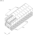
- the magnetic alignment device 10 has a configuration including: a first magnet part 110a and a second magnet part 110b, which are located at an upper and lower portion, respectively, along a transfer direction of a negative electrode current collector to which a negative electrode slurry including a carbon-based negative electrode active material is applied, as shown in FIG. 1 ; and a drying part 120 for drying the negative electrode slurry to which a magnetic force is applied by the first magnet part 110a and the second magnet part 110b.
- the first magnet part 110a and the second magnet part 110b are disposed on the upper and lower portions of the electrode sheet being transferred, that is, the negative electrode current collector on which the negative electrode slurry is applied, respectively, to play a role in applying a magnetic field to the surface of the negative electrode slurry S.
- the first magnet part 110a and second magnet part 110b may include magnets 111a, 111b for applying a magnetic field to the surface of the negative electrode slurry S, respectively, and support parts 112a, 112b for fixing the magnets.
- the first magnet part 110a and the second magnet part 110b may include a plurality of unit magnets in the x-axis direction and the y-axis direction, respectively, m (wherein m is an integer greater than or equal to 2) and n (wherein n is an integer greater than or equal to 2) unit magnets may be included in the x-axis direction and the y-axis direction, respectively, to form a magnet array, whereby one magnet part may include m ⁇ n unit magnets.
- first magnet part 110a and second magnet part 110b can be divided into first regions 1111a, 1111b located upstream and second regions 1112a, 1112b located downstream in the transfer direction of the negative electrode current collector, that is, in the x-axis direction.
- first regions 1111a, 1111b may apply a magnetic field with a stronger magnetic force (or magnetic field intensity) than the second regions 1112a, 1112b.
- This difference in magnetic force intensity may be implemented in any manner conventional in the art, but is preferably implemented by arranging the plurality of unit magnets disposed in the first regions 1111a, 1111b in a Halbach arrangement and the plurality of unit magnets disposed in the second regions 1112a, 1112b so that the magnetic force of the N pole or S pole (i.e., a single pole) is exposed to the surface of the magnet part to apply a uniform magnetic field.
- the Halbach arrangement refers to an arrangement method in which the field strength is improved by controlling the arrangement of the unit magnets, and a stronger magnetic force of 1.5 times or more can be realized compared to the case in which the unit magnets are arranged with the same poles.
- the present invention enables a high magnetic field to be applied in the first regions 1111a and 1111b, which are located upstream relative to the transfer direction, and a relatively low magnetic field to be applied in the second regions 1112a, 1112b, which are located downstream relative to the first regions 1111a, 1111b, when transferring a negative electrode slurry.
- the present invention can prevent the alignment of the carbon-based negative electrode active material aligned perpendicularly to the negative electrode current collector from being reduced due to a strong magnetic field at the end of the magnet part, and can reduce the stress on the negative electrode slurry, thereby improving the surface properties of the negative electrode active layer to be manufactured.
- the first region 1111a and 1111b and the second region 1112a and 1112b may have a certain ratio of the magnetic force applied on the surface of the first magnet part 110a and the second magnet part 110b and/or the magnetic force applied in the space between the first magnet part 110a and the second magnet part 110b.
- the first regions 1111a, 1111b may have a magnetic force applied to the space between the first magnet part 110a and the second magnet part 110b of 8,000 G or more, 9,000 G or more, 10,000 G or more, 8,000 to 12,000 G, or 8,500 to 11,000 G, and the ratio of the magnetic force of the first regions 1111a, 1111b to the second regions 1112a, 1112b may be 1.4 or more, 1.5 or more, 1.6 or more, 1.4 to 2.5, 1.4 to 2.2, 1.5 to 1.8, or 1.6 to 2.0.
- the first regions 1111a and 1111b may apply a magnetic force to the surfaces of the first magnet part 110a and the second magnet part 110b of 10,000 G or more, 11,000 G or more, 10,000 to 15,000 G, 10,000 to 12,000 G, or 11,000 to 12,000 G, and the ratio of the magnetic force of the first regions 1111a, 1111b to the second regions 1112a, 1112b may be 1.4 or more, 1.5 or more, 1.6 or more, 1.4 to 5.0, 1.4 to 3.0, 1.4 to 2.5, or 1.5 to 2.0.
- first regions 1111a, 1111b and the second regions 1112a, 1112b may be adjusted such that the size ratio of the regions is constant.
- the first regions 1111a, 1111b may have a length in the transfer direction of the negative electrode current collector that is shorter than the second regions 1112a, 1112b.
- the first regions 1111a, 1111b may account for 5-50%, or more specifically, 5-40%, 10-30%, or 10-20%, of the total length of the first magnet part 110a and the second magnet part 1 10b, and may have a structure such that the second regions 1112a, 1112b account for the remainder.
- the first regions 1111a, 1111b may occupy 15% based on the total length of the first magnet part 110a and the second magnet part 110b, and the second regions 1112a, 1112b may be connected continuously with the first regions 1111a, 1111b to occupy 85% based on the total length of the first magnet part 110a and the second magnet part 110b.
- the present invention can effectively control the alignment of the carbon-based negative electrode active material, as well as significantly lower the stress on the negative electrode slurry.
- the unit magnets may include electromagnets and/or permanent magnets.
- the electromagnets may include both direct current electromagnets and alternating current electromagnets.
- the permanent magnets may include both ferromagnetic and soft magnetic magnets, including NdFeB-based magnets, SmCo-based magnets, Ferrite magnets, Alnico magnets, FeCrCo-based magnets, Bond magnets (Nd-Fe-B-based, Sm-Fe-N-based, Sm-Co-based, Ferrite-based), and the like.
- first magnet part 110a and the second magnet part 110b may be located along the transfer direction of the negative electrode slurry S so as to face each other, and may be arranged to have opposite poles.
- the N poles of the first magnets of the first magnet part 110a and the S poles of the second magnets of the second magnet part 110b may be facing each other, or the S poles of the first magnets of the first magnet part 110a and the N poles of the second magnets of the second magnet part 110b may be facing each other.
- the separation distance of the first magnet part 110a and the second magnet part 110b may be 10 mm to 50 mm, more specifically, 10 mm to 40 mm; 20 mm to 50 mm; or 15 mm to 45 mm.
- the present invention can perform alignment of the carbon-based negative electrode active material contained in the negative electrode slurry S more efficiently.
- first magnet part 110a and the second magnet part 110b may have a length of 0.5 m to 10 m in the transfer direction of the negative electrode current collector (i.e., the x-axis direction), and the length of the first magnet part 110a and the second magnet part 110b may be appropriately adjusted according to the transferring speed of the negative electrode current collector to which the negative electrode slurry is applied and/or the time for which a magnetic force is applied to the negative electrode slurry in the manufacture of the negative electrode.
- the present invention can realize an alignment of the carbon-based negative electrode active material contained in the negative electrode slurry close to vertical.
- the magnetic alignment device 10 is coupled with a transferring part 20, which is capable of transferring a negative electrode current collector on which a negative electrode slurry including a carbon-based negative electrode active material has been applied in one direction, specifically in the process direction.
- the transferring part 20 can be applied in any manner conventionally applied in the art for transferring an electrode sheet C on which an electrode slurry S has been applied in electrode manufacturing, without limitation.
- the transferring part 20 may be applied in a roll-to-roll method, a conveyor belt transfer method capable of applying a magnetic field, or the like.
- the drying part 120 plays a role in drying the negative electrode slurry S in which the carbon-based negative electrode active material is aligned by the first magnet part 110a and the second magnet part 110b to fix the aligned carbon-based negative electrode active material.
- the drying part 120 is formed by including a wall body (not shown) that blocks the periphery except for the inlet and outlet for bringing in and taking out the electrode sheet to which the slurry S is applied, and a dryer (not shown) for drying the electrode sheet on the wall body of the side from which the electrode sheet to which the electrode slurry is applied is taken out.
- the wall body is preferably made of an insulating material to prevent heat loss due to the transfer of internal energy to the outside.
- the drying part 120 may be configured to perform a two-step drying process to maintain alignment of the carbon-based negative electrode active material contained within the negative electrode active layer.
- the drying part 120 may include a first dryer that dries the negative electrode slurry using light and a second dryer that dries the negative electrode slurry using heat, and the first and second dryers may operate continuously to dry the negative electrode slurry.
- the first dryer is a device for drying the negative electrode slurry, wherein the surface of the negative electrode slurry may be irradiated with light or wavelengths as described above.
- drying of the negative electrode slurry is performed by applying hot air at a high temperature, which can lead to a long drying time of the negative electrode slurry and disordering of the alignment of the carbon-based negative electrode active material in the negative electrode slurry.
- the temperature of the hot air is increased to solve these problems, the tendency of drying on the surface of the slurry increases, so that the binder is concentrated on the surface of the slurry along with the volatilized solvent, resulting in a migration phenomenon, which reduces the adhesion strength of the active material layer and the negative electrode current collector.
- the present invention may be configured to preliminarily dry the electrode slurry by irradiating the electrode slurry with energy in the form of light or wavelengths using a first dryer to dry the electrode slurry while maintaining a high alignment of the carbon-based negative electrode active material without these problems.
- a first dryer may include, for example, an ultraviolet dryer, a near-infrared dryer, a far-infrared dryer, or the like, and may specifically include a far-infrared dryer that emits energy with a wavelength of 1 ⁇ m or greater, more specifically 5 ⁇ m or greater, 10 ⁇ m or greater, or 20 ⁇ m or greater, to achieve a uniform drying rate of the electrode slurry.
- the far-infrared dryer unlike the near-infrared dryer or infrared dryer conventionally applied in the art, has the advantage of being energy efficient due to its long light or wavelength, and can apply energy uniformly to the interior as well as the surface of the negative electrode slurry, thereby increasing the adhesion between the negative electrode slurry and the negative electrode current collector in a short time.
- the first dryer may emit energy at an output density of 50 kW/m 2 to 1,000 kW/m 2 , more specifically, 50 kW/m 2 to 500 kW/m 2 ; 50 kW/m 2 to 250 kW/m 2 ; or 50 kW/m 2 and 200 kW/m 2 .
- the present invention can prevent an excessive output density from inducing uneven drying of the active material layer.
- the second dryer may apply heat to the negative electrode slurry preliminarily dried by light or wavelength to uniformly and completely dry it.
- Such second dryers may include, without limitation, those of ordinary skill in the art, but more particularly may include hot air dryers, vacuum ovens, and the like, either singly or in combination.
- the magnetic alignment device has the above-described configuration, which can reduce the phenomenon of attraction of the carbon-based negative electrode active material by the magnetic force generated at the end of the magnet part, and thus can significantly increase the alignment the carbon-based negative electrode active material contained in the negative electrode slurry, and has the advantage of manufacturing a negative electrode with excellent electrical performance due to the excellent surface characteristics of the manufactured negative electrode active layer.
- an electrode manufacturing method including:
- the manufacturing method of a negative electrode according to the present invention includes applying a negative electrode slurry including carbon-based negative electrode active material on a negative electrode current collector, and applying a magnetic field to a surface of the applied negative electrode slurry using a magnetic alignment device of the present invention described above to align the carbon-based negative electrode active material in the negative electrode slurry to be vertical or near vertical with respect to the surface of the negative electrode current collector (or with respect to the transfer direction of the electrode sheet), wherein, after alignment of the carbon-based negative electrode active materials, significant stress is applied to the aligned carbon-based negative electrode active materials in the slurry to prevent the formation of scratches or crater-like grooves on the surface of the manufactured negative electrode active layer.
- the step of applying the negative electrode slurry to the negative electrode current collector and the step of drying the negative electrode slurry may be performed in a manner conventionally applied in the art.
- a magnetic field of different magnetic forces may be sequentially applied to the negative electrode slurry applied to the surface of the negative electrode current collector using the magnetic alignment device according to the present invention.
- the magnetic alignment device has a first magnet part and a second magnet part disposed at the upper and lower portions of the negative electrode current collector, respectively, along the transfer direction of the negative electrode current collector (i.e., the x-axis direction).
- the first magnet part and said second magnet part can be divided into first regions 1111a, 1111b located upstream and second regions 1112a, 1112b located downstream along the transfer direction of the negative electrode current collector, i.e., in the x-axis direction, and the first regions 1111a, 1111b can apply a magnetic field having a stronger magnetic force than the second regions 1112a, 1112b.
- the first region 1111a, 1111b and the second region 1112a, 1112b may have a certain ratio of magnetic forces applied on the surfaces of the first magnet part and the second magnet part and/or magnetic forces applied in the space between the first magnet part and the second magnet part.
- the first regions 1111a, 1111b may have a magnetic force applied to the space between the first magnet part 110a and the second magnet part 110b of 8,000 G or more, 9,000 G or more, 10,000 G or more, 8,000 to 12,000 G, or 8,500 to 11,000 G, and the ratio of the magnetic force in the first regions 1111a, 1111b to the second regions 1112a, 1112b may be 1.4 or more, 1.5 or more, 1.6 or more, 1.4 to 2.5, 1.4 to 2.2, 1.5 to 1.8, or 1.6 to 2.0.
- the first regions 1111a, 1111b may apply a magnetic force to the surfaces of the first magnet part 110a and the second magnet part 110b of 10,000 G or more, 11,000 G or more, 10,000 to 15,000 G, 10,000 to 12,000 G, or 11,000 to 12,000 G, and the ratio of the magnetic force of the first regions 1111a, 1111b to the second regions 1112a, 1112b may be 1.4 or more, 1.5 or more, 1.6 or more, 1.4 to 5.0, 1.4 to 3.0, 1.4 to 2.5, or 1.5 to 2.0.
- the present invention can prevent the alignment of the carbon-based negative electrode active material aligned perpendicularly to the negative electrode current collector from being reduced due to a strong magnetic field at the end of the magnet part, and the stress applied to the negative electrode slurry can be reduced, thereby improving the surface properties of the negative electrode active layer manufactured.
- the magnetic field may be applied for a time period of 0.1 to 20 seconds, and more specifically, may be applied for a time period of 0.5 to 15 seconds; 0.5 to 12 seconds; 1 to 10 seconds; 2 to 8 seconds; or 2 to 5 seconds.
- the carbon-based negative electrode active material contained in the negative electrode slurry may include those conventionally applied as carbon-based negative electrode active materials in lithium secondary batteries.
- the carbon-based negative electrode active material refers to a material having carbon atoms as its main component, and such carbon-based negative electrode active material may include graphite.
- the graphite may include one or more of natural graphite, synthetic graphite, but preferably natural graphite, or a mixture of natural and synthetic graphite.
- the negative electrode slurry may further include a conductor, a binder, a thickener, and the like, which may be applied as those conventionally used in the art.
- a negative electrode for a lithium secondary battery in which a carbon-based negative electrode active material is aligned perpendicularly to the negative electrode current collector was prepared.
- natural graphite was first used to prepare the negative electrode active material, and 97 parts by weight of the negative electrode active material and 3 parts by weight of styrene butadiene rubber (SBR) were mixed with water to form a negative electrode slurry, and then the negative electrode slurry was cast on a copper sheet that was being transferred roll-to-roll (transfer speed: 5 m/min) using a die coater. At this time, the negative electrode slurry was cast to an average thickness of 165 ⁇ m along the transfer direction of the copper sheet.
- SBR styrene butadiene rubber
- a magnetic field was applied to the negative electrode slurry by moving the copper sheet so that the applied negative electrode slurry passed between the first magnet part and the second magnet part of the magnetic alignment device.
- the first magnet part and the second magnet part were adjusted to have a separation distance of 20 mm (1/2 value of the separation distance: 10 mm).
- first magnet part and the second magnet part are divided into a first region located upstream and a second region located downstream based on the transfer direction of the negative electrode current collector, and the following was adjusted as shown in Table 1 below: 1 the arrangement of the unit magnets included in the first region and the second region, respectively, 2 the magnetic field strength of the magnet surface included in each region, and 3 the ratio (L 1 /L 2 ) of the length of the first region (L 1 ) and the length of the second region (L 2 ) in the transfer direction of the negative electrode current collector.
- X-ray diffraction spectroscopy of the negative electrode active layer was performed on the negative electrodes prepared in Examples 1-2 and Comparative Examples 1-3 to measure the spectrum.
- the measurement conditions of the X-ray diffraction (XRD) were as follows:
- a negative electrode for a lithium secondary battery manufactured using a magnetic alignment device according to the present invention can produce a negative electrode for a lithium secondary battery with a high alignment degree of the carbon-based negative electrode active material and excellent surface properties.
- the negative electrode of the example manufactured using the magnetic alignment device according to the present invention has a significantly lower alignment (I 004 /I 110 ) of the carbon-based negative electrode active material of less than 0.5, no surface damage of the negative electrode active layer, and an arithmetic mean height (Sa) of the negative electrode active layer surface of 3.0 to 6.0 ⁇ m.
- the magnetic alignment device can adjust the alignment of the carbon-based negative electrode active material contained in the negative electrode slurry and the arithmetic mean height (Sa) of the surface of the negative electrode active layer to a certain range by having a magnet part that applies a stronger magnetic force to the first region located upstream along the transfer direction of the negative electrode current collector than the second region located downstream.
Landscapes
- Chemical & Material Sciences (AREA)
- Engineering & Computer Science (AREA)
- Chemical Kinetics & Catalysis (AREA)
- Electrochemistry (AREA)
- General Chemical & Material Sciences (AREA)
- Manufacturing & Machinery (AREA)
- Materials Engineering (AREA)
- Physics & Mathematics (AREA)
- Electromagnetism (AREA)
- Power Engineering (AREA)
- Inorganic Chemistry (AREA)
- Battery Electrode And Active Subsutance (AREA)
Applications Claiming Priority (2)
| Application Number | Priority Date | Filing Date | Title |
|---|---|---|---|
| KR1020220131366A KR102617498B1 (ko) | 2022-10-13 | 2022-10-13 | 리튬 이차전지용 음극 및 이를 위한 음극용 자성 정렬 장치 |
| PCT/KR2023/014426 WO2024080617A1 (fr) | 2022-10-13 | 2023-09-21 | Électrode négative pour batterie secondaire au lithium, et dispositif d'alignement magnétique pour la même électrode négative |
Publications (2)
| Publication Number | Publication Date |
|---|---|
| EP4421900A1 true EP4421900A1 (fr) | 2024-08-28 |
| EP4421900A4 EP4421900A4 (fr) | 2025-09-03 |
Family
ID=89377710
Family Applications (1)
| Application Number | Title | Priority Date | Filing Date |
|---|---|---|---|
| EP23877545.6A Pending EP4421900A4 (fr) | 2022-10-13 | 2023-09-21 | Électrode négative pour batterie secondaire au lithium, et dispositif d'alignement magnétique pour la même électrode négative |
Country Status (6)
| Country | Link |
|---|---|
| US (1) | US12322786B2 (fr) |
| EP (1) | EP4421900A4 (fr) |
| JP (1) | JP2024545453A (fr) |
| KR (1) | KR102617498B1 (fr) |
| CN (1) | CN118369786A (fr) |
| WO (1) | WO2024080617A1 (fr) |
Families Citing this family (6)
| Publication number | Priority date | Publication date | Assignee | Title |
|---|---|---|---|---|
| KR102949604B1 (ko) * | 2023-02-20 | 2026-04-07 | 에스케이온 주식회사 | 급속충전 성능이 향상된 음극 및 음극 제조 방법 및 음극 제조장치 |
| KR20250104350A (ko) * | 2023-12-29 | 2025-07-08 | 주식회사 엘지에너지솔루션 | 자성 정렬 장치 및 이를 이용한 전극 내 전극활물질의 자성 정렬 방법 |
| KR102801794B1 (ko) * | 2024-01-08 | 2025-05-02 | 동아대학교 산학협력단 | 자기 배향 장치 |
| CN120824310A (zh) * | 2024-04-15 | 2025-10-21 | 比亚迪股份有限公司 | 负极及其制备方法、二次电池及用电设备 |
| KR20260014378A (ko) * | 2024-07-23 | 2026-01-30 | 주식회사 엘지에너지솔루션 | 리튬 이차전지용 음극 및 이의 제조방법 |
| KR20260031313A (ko) * | 2024-08-28 | 2026-03-09 | 주식회사 엘지에너지솔루션 | 이차 전지 제조 설비 및 이를 이용한 이차 전지를 제조하는 방법 셀 |
Family Cites Families (20)
| Publication number | Priority date | Publication date | Assignee | Title |
|---|---|---|---|---|
| JP2004220926A (ja) | 2003-01-15 | 2004-08-05 | Matsushita Electric Ind Co Ltd | 非水電解質二次電池用負極 |
| JP5073105B2 (ja) | 2010-06-30 | 2012-11-14 | パナソニック株式会社 | 非水電解質二次電池用負極およびその製造方法、ならびに非水電解質二次電池 |
| JP5601550B2 (ja) * | 2011-02-18 | 2014-10-08 | トヨタ自動車株式会社 | リチウムイオン二次電池とその製造方法 |
| WO2012124033A1 (fr) | 2011-03-11 | 2012-09-20 | トヨタ自動車株式会社 | Batterie secondaire à électrolyte non aqueux et son procédé de fabrication |
| US9911972B2 (en) * | 2011-12-14 | 2018-03-06 | Toyota Jidosha Kabushiki Kaisha | Non-aqueous electrolyte secondary battery and method for manufacturing negative electrode for secondary battery |
| EP4593395A3 (fr) | 2012-10-01 | 2025-10-01 | GE Video Compression, LLC | Codage vidéo échelonnable utilisant la contribution de la prédiction inter-couche à la prédiction de couche d'amélioration |
| CN203826481U (zh) * | 2014-04-16 | 2014-09-10 | 山东精工电子科技有限公司 | 提高磷酸铁锂正极材料压实密度的装置 |
| JP6696797B2 (ja) | 2016-03-02 | 2020-05-20 | 株式会社日本マイクロニクス | シート分離装置、シート分離方法、及びシート状二次電池の製造方法 |
| CH712877A2 (de) * | 2016-09-06 | 2018-03-15 | Battrion Ag | Verfahren und Einrichtung zur kontinuierlichen Applizierung magnetischer Felder auf einen Gegenstand. |
| KR102432049B1 (ko) * | 2016-09-30 | 2022-08-16 | 주식회사 엘지에너지솔루션 | 리튬 이차전지용 전극 및 이를 구비한 리튬 이차전지 |
| KR102417267B1 (ko) | 2016-11-02 | 2022-07-04 | 삼성에스디아이 주식회사 | 리튬 이차 전지 |
| JP7013773B2 (ja) * | 2017-09-29 | 2022-02-01 | 三洋電機株式会社 | 非水電解質二次電池及びその製造方法 |
| KR101972235B1 (ko) | 2017-10-25 | 2019-08-23 | 재단법인대구경북과학기술원 | 리튬이차전지 음극 제조방법 및 리튬이차전지 제조방법 |
| CN109994706B (zh) * | 2018-04-28 | 2020-08-28 | 宁德时代新能源科技股份有限公司 | 锂离子电池 |
| CN109950474B (zh) * | 2018-06-29 | 2020-04-24 | 宁德时代新能源科技股份有限公司 | 锂离子电池 |
| EP3879601B1 (fr) | 2019-12-03 | 2024-05-29 | Contemporary Amperex Technology Co., Limited | Batterie secondaire, dispositif, graphite artificiel, et procédé de préparation associé |
| DE102019135308A1 (de) | 2019-12-19 | 2021-06-24 | Battrion Ag | Verfahren und Vorrichtung zur Ausrichtung von Partikeln in einer Paste |
| KR102527051B1 (ko) | 2020-11-02 | 2023-05-02 | 에스케이온 주식회사 | 리튬 이차 전지용 음극, 그 제조방법 및 이를 포함하는 리튬 이차전지 |
| JP7819459B2 (ja) * | 2021-10-18 | 2026-02-25 | 日本ゼオン株式会社 | 非水系二次電池用負極材料シートおよびその製造方法、非水系二次電池用負極、並びに、非水系二次電池 |
| KR20230111296A (ko) * | 2022-01-18 | 2023-07-25 | 에스케이온 주식회사 | 이차전지용 음극, 음극 제조방법 및 상기 음극을 포함하는 이차전지 |
-
2022
- 2022-10-13 KR KR1020220131366A patent/KR102617498B1/ko active Active
-
2023
- 2023-09-21 WO PCT/KR2023/014426 patent/WO2024080617A1/fr not_active Ceased
- 2023-09-21 EP EP23877545.6A patent/EP4421900A4/fr active Pending
- 2023-09-21 JP JP2024533306A patent/JP2024545453A/ja active Pending
- 2023-09-21 CN CN202380014978.0A patent/CN118369786A/zh active Pending
- 2023-09-21 US US18/719,377 patent/US12322786B2/en active Active
Also Published As
| Publication number | Publication date |
|---|---|
| US20240429366A1 (en) | 2024-12-26 |
| WO2024080617A1 (fr) | 2024-04-18 |
| EP4421900A4 (fr) | 2025-09-03 |
| CN118369786A (zh) | 2024-07-19 |
| US12322786B2 (en) | 2025-06-03 |
| KR102617498B1 (ko) | 2023-12-27 |
| JP2024545453A (ja) | 2024-12-06 |
Similar Documents
| Publication | Publication Date | Title |
|---|---|---|
| EP4421900A1 (fr) | Électrode négative pour batterie secondaire au lithium, et dispositif d'alignement magnétique pour la même électrode négative | |
| EP4418353A1 (fr) | Appareil d'alignement de magnétisme pour électrodes négatives et procédé de fabrication d'électrode négative l'utilisant | |
| EP4421901A1 (fr) | Dispositif d'alignement magnétique pour anode, et procédé de fabrication d'anode l'utilisant | |
| EP4443548A1 (fr) | Appareil d'alignement magnétique pour électrodes négatives et procédé de fabrication d'électrodes négatives correspondant | |
| EP4447149A1 (fr) | Appareil d'alignement de magnétisme pour électrodes négatives et procédé de fabrication d'électrodes négatives l'utilisant | |
| EP4478446A1 (fr) | Électrode négative pour batterie secondaire au lithium et procédé pour la fabriquer | |
| EP4503156A1 (fr) | Dispositif de fabrication d'électrode négative pour batterie rechargeable | |
| KR102588919B1 (ko) | 리튬 이차전지용 음극 및 이를 포함하는 리튬 이차전지 | |
| KR20240038296A (ko) | 음극용 자성 정렬 장치 및 이를 이용한 음극의 제조방법 | |
| EP4447151A1 (fr) | Appareil d'alignement de magnétisme pour électrodes négatives et procédé de fabrication d'électrodes négatives l'utilisant | |
| EP4535443A1 (fr) | Anode pour batterie secondaire au lithium et appareil de fabrication d'anode associé | |
| EP4447150A1 (fr) | Appareil d'alignement de magnétisme pour électrodes négatives et procédé de fabrication d'électrodes négatives utilisant celui-ci | |
| EP4503157A1 (fr) | Appareil de fabrication d'anode pour batterie secondaire | |
| EP4503159A1 (fr) | Appareil de fabrication d'anode de batterie secondaire | |
| EP4451410A1 (fr) | Ensemble électrode de type enroulement et batterie secondaire au lithium le comprenant | |
| Rana et al. | Ball-Milled Graphite-Tin Composite Anode Materials for Lithium-Ion Battery |
Legal Events
| Date | Code | Title | Description |
|---|---|---|---|
| STAA | Information on the status of an ep patent application or granted ep patent |
Free format text: STATUS: THE INTERNATIONAL PUBLICATION HAS BEEN MADE |
|
| PUAI | Public reference made under article 153(3) epc to a published international application that has entered the european phase |
Free format text: ORIGINAL CODE: 0009012 |
|
| STAA | Information on the status of an ep patent application or granted ep patent |
Free format text: STATUS: REQUEST FOR EXAMINATION WAS MADE |
|
| 17P | Request for examination filed |
Effective date: 20240524 |
|
| AK | Designated contracting states |
Kind code of ref document: A1 Designated state(s): AL AT BE BG CH CY CZ DE DK EE ES FI FR GB GR HR HU IE IS IT LI LT LU LV MC ME MK MT NL NO PL PT RO RS SE SI SK SM TR |
|
| RIC1 | Information provided on ipc code assigned before grant |
Ipc: H01M 4/02 20060101ALI20250331BHEP Ipc: H01F 7/02 20060101ALI20250331BHEP Ipc: H01M 4/583 20100101ALI20250331BHEP Ipc: H01M 4/1393 20100101ALI20250331BHEP Ipc: H01M 4/04 20060101ALI20250331BHEP Ipc: H01M 4/133 20100101AFI20250331BHEP |
|
| A4 | Supplementary search report drawn up and despatched |
Effective date: 20250731 |
|
| RIC1 | Information provided on ipc code assigned before grant |
Ipc: H01M 4/133 20100101AFI20250725BHEP Ipc: H01M 4/04 20060101ALI20250725BHEP Ipc: H01M 4/1393 20100101ALI20250725BHEP Ipc: H01M 4/583 20100101ALI20250725BHEP Ipc: H01F 7/02 20060101ALI20250725BHEP Ipc: H01M 4/02 20060101ALI20250725BHEP Ipc: H01M 10/058 20100101ALI20250725BHEP |
|
| DAV | Request for validation of the european patent (deleted) | ||
| DAX | Request for extension of the european patent (deleted) |