EP4421922A1 - Brennstoffzellenkatalysator, verfahren zur herstellung davon und brennstoffzelle damit - Google Patents
Brennstoffzellenkatalysator, verfahren zur herstellung davon und brennstoffzelle damit Download PDFInfo
- Publication number
- EP4421922A1 EP4421922A1 EP22901691.0A EP22901691A EP4421922A1 EP 4421922 A1 EP4421922 A1 EP 4421922A1 EP 22901691 A EP22901691 A EP 22901691A EP 4421922 A1 EP4421922 A1 EP 4421922A1
- Authority
- EP
- European Patent Office
- Prior art keywords
- metal catalyst
- support
- fuel cell
- catalyst particles
- pores
- Prior art date
- Legal status (The legal status is an assumption and is not a legal conclusion. Google has not performed a legal analysis and makes no representation as to the accuracy of the status listed.)
- Pending
Links
Images


Classifications
-
- H—ELECTRICITY
- H01—ELECTRIC ELEMENTS
- H01M—PROCESSES OR MEANS, e.g. BATTERIES, FOR THE DIRECT CONVERSION OF CHEMICAL ENERGY INTO ELECTRICAL ENERGY
- H01M8/00—Fuel cells; Manufacture thereof
- H01M8/10—Fuel cells with solid electrolytes
- H01M8/1016—Fuel cells with solid electrolytes characterised by the electrolyte material
- H01M8/1018—Polymeric electrolyte materials
-
- B—PERFORMING OPERATIONS; TRANSPORTING
- B22—CASTING; POWDER METALLURGY
- B22F—WORKING METALLIC POWDER; MANUFACTURE OF ARTICLES FROM METALLIC POWDER; MAKING METALLIC POWDER; APPARATUS OR DEVICES SPECIALLY ADAPTED FOR METALLIC POWDER
- B22F1/00—Metallic powder; Treatment of metallic powder, e.g. to facilitate working or to improve properties
- B22F1/05—Metallic powder characterised by the size or surface area of the particles
- B22F1/052—Metallic powder characterised by the size or surface area of the particles characterised by a mixture of particles of different sizes or by the particle size distribution
-
- B—PERFORMING OPERATIONS; TRANSPORTING
- B22—CASTING; POWDER METALLURGY
- B22F—WORKING METALLIC POWDER; MANUFACTURE OF ARTICLES FROM METALLIC POWDER; MAKING METALLIC POWDER; APPARATUS OR DEVICES SPECIALLY ADAPTED FOR METALLIC POWDER
- B22F1/00—Metallic powder; Treatment of metallic powder, e.g. to facilitate working or to improve properties
- B22F1/05—Metallic powder characterised by the size or surface area of the particles
- B22F1/054—Nanosized particles
-
- B—PERFORMING OPERATIONS; TRANSPORTING
- B22—CASTING; POWDER METALLURGY
- B22F—WORKING METALLIC POWDER; MANUFACTURE OF ARTICLES FROM METALLIC POWDER; MAKING METALLIC POWDER; APPARATUS OR DEVICES SPECIALLY ADAPTED FOR METALLIC POWDER
- B22F1/00—Metallic powder; Treatment of metallic powder, e.g. to facilitate working or to improve properties
- B22F1/18—Non-metallic particles coated with metal
-
- B—PERFORMING OPERATIONS; TRANSPORTING
- B22—CASTING; POWDER METALLURGY
- B22F—WORKING METALLIC POWDER; MANUFACTURE OF ARTICLES FROM METALLIC POWDER; MAKING METALLIC POWDER; APPARATUS OR DEVICES SPECIALLY ADAPTED FOR METALLIC POWDER
- B22F9/00—Making metallic powder or suspensions thereof
- B22F9/16—Making metallic powder or suspensions thereof using chemical processes
- B22F9/18—Making metallic powder or suspensions thereof using chemical processes with reduction of metal compounds
- B22F9/24—Making metallic powder or suspensions thereof using chemical processes with reduction of metal compounds starting from liquid metal compounds, e.g. solutions
-
- C—CHEMISTRY; METALLURGY
- C22—METALLURGY; FERROUS OR NON-FERROUS ALLOYS; TREATMENT OF ALLOYS OR NON-FERROUS METALS
- C22C—ALLOYS
- C22C1/00—Making non-ferrous alloys
- C22C1/04—Making non-ferrous alloys by powder metallurgy
- C22C1/0466—Alloys based on noble metals
-
- H—ELECTRICITY
- H01—ELECTRIC ELEMENTS
- H01M—PROCESSES OR MEANS, e.g. BATTERIES, FOR THE DIRECT CONVERSION OF CHEMICAL ENERGY INTO ELECTRICAL ENERGY
- H01M4/00—Electrodes
- H01M4/86—Inert electrodes with catalytic activity, e.g. for fuel cells
- H01M4/88—Processes of manufacture
- H01M4/8825—Methods for deposition of the catalytic active composition
- H01M4/8842—Coating using a catalyst salt precursor in solution followed by evaporation and reduction of the precursor
-
- H—ELECTRICITY
- H01—ELECTRIC ELEMENTS
- H01M—PROCESSES OR MEANS, e.g. BATTERIES, FOR THE DIRECT CONVERSION OF CHEMICAL ENERGY INTO ELECTRICAL ENERGY
- H01M4/00—Electrodes
- H01M4/86—Inert electrodes with catalytic activity, e.g. for fuel cells
- H01M4/88—Processes of manufacture
- H01M4/8825—Methods for deposition of the catalytic active composition
- H01M4/8846—Impregnation
- H01M4/885—Impregnation followed by reduction of the catalyst salt precursor
-
- H—ELECTRICITY
- H01—ELECTRIC ELEMENTS
- H01M—PROCESSES OR MEANS, e.g. BATTERIES, FOR THE DIRECT CONVERSION OF CHEMICAL ENERGY INTO ELECTRICAL ENERGY
- H01M4/00—Electrodes
- H01M4/86—Inert electrodes with catalytic activity, e.g. for fuel cells
- H01M4/88—Processes of manufacture
- H01M4/8878—Treatment steps after deposition of the catalytic active composition or after shaping of the electrode being free-standing body
- H01M4/8882—Heat treatment, e.g. drying, baking
-
- H—ELECTRICITY
- H01—ELECTRIC ELEMENTS
- H01M—PROCESSES OR MEANS, e.g. BATTERIES, FOR THE DIRECT CONVERSION OF CHEMICAL ENERGY INTO ELECTRICAL ENERGY
- H01M4/00—Electrodes
- H01M4/86—Inert electrodes with catalytic activity, e.g. for fuel cells
- H01M4/88—Processes of manufacture
- H01M4/8878—Treatment steps after deposition of the catalytic active composition or after shaping of the electrode being free-standing body
- H01M4/8892—Impregnation or coating of the catalyst layer, e.g. by an ionomer
-
- H—ELECTRICITY
- H01—ELECTRIC ELEMENTS
- H01M—PROCESSES OR MEANS, e.g. BATTERIES, FOR THE DIRECT CONVERSION OF CHEMICAL ENERGY INTO ELECTRICAL ENERGY
- H01M4/00—Electrodes
- H01M4/86—Inert electrodes with catalytic activity, e.g. for fuel cells
- H01M4/90—Selection of catalytic material
- H01M4/92—Metals of platinum group
-
- H—ELECTRICITY
- H01—ELECTRIC ELEMENTS
- H01M—PROCESSES OR MEANS, e.g. BATTERIES, FOR THE DIRECT CONVERSION OF CHEMICAL ENERGY INTO ELECTRICAL ENERGY
- H01M4/00—Electrodes
- H01M4/86—Inert electrodes with catalytic activity, e.g. for fuel cells
- H01M4/90—Selection of catalytic material
- H01M4/92—Metals of platinum group
- H01M4/921—Alloys or mixtures with metallic elements
-
- H—ELECTRICITY
- H01—ELECTRIC ELEMENTS
- H01M—PROCESSES OR MEANS, e.g. BATTERIES, FOR THE DIRECT CONVERSION OF CHEMICAL ENERGY INTO ELECTRICAL ENERGY
- H01M4/00—Electrodes
- H01M4/86—Inert electrodes with catalytic activity, e.g. for fuel cells
- H01M4/90—Selection of catalytic material
- H01M4/92—Metals of platinum group
- H01M4/925—Metals of platinum group supported on carriers, e.g. powder carriers
-
- H—ELECTRICITY
- H01—ELECTRIC ELEMENTS
- H01M—PROCESSES OR MEANS, e.g. BATTERIES, FOR THE DIRECT CONVERSION OF CHEMICAL ENERGY INTO ELECTRICAL ENERGY
- H01M8/00—Fuel cells; Manufacture thereof
- H01M8/10—Fuel cells with solid electrolytes
- H01M2008/1095—Fuel cells with polymeric electrolytes
-
- H—ELECTRICITY
- H01—ELECTRIC ELEMENTS
- H01M—PROCESSES OR MEANS, e.g. BATTERIES, FOR THE DIRECT CONVERSION OF CHEMICAL ENERGY INTO ELECTRICAL ENERGY
- H01M4/00—Electrodes
- H01M4/86—Inert electrodes with catalytic activity, e.g. for fuel cells
- H01M4/90—Selection of catalytic material
- H01M4/9075—Catalytic material supported on carriers, e.g. powder carriers
- H01M4/9083—Catalytic material supported on carriers, e.g. powder carriers on carbon or graphite
-
- H—ELECTRICITY
- H01—ELECTRIC ELEMENTS
- H01M—PROCESSES OR MEANS, e.g. BATTERIES, FOR THE DIRECT CONVERSION OF CHEMICAL ENERGY INTO ELECTRICAL ENERGY
- H01M4/00—Electrodes
- H01M4/86—Inert electrodes with catalytic activity, e.g. for fuel cells
- H01M4/90—Selection of catalytic material
- H01M4/92—Metals of platinum group
- H01M4/925—Metals of platinum group supported on carriers, e.g. powder carriers
- H01M4/926—Metals of platinum group supported on carriers, e.g. powder carriers on carbon or graphite
-
- Y—GENERAL TAGGING OF NEW TECHNOLOGICAL DEVELOPMENTS; GENERAL TAGGING OF CROSS-SECTIONAL TECHNOLOGIES SPANNING OVER SEVERAL SECTIONS OF THE IPC; TECHNICAL SUBJECTS COVERED BY FORMER USPC CROSS-REFERENCE ART COLLECTIONS [XRACs] AND DIGESTS
- Y02—TECHNOLOGIES OR APPLICATIONS FOR MITIGATION OR ADAPTATION AGAINST CLIMATE CHANGE
- Y02E—REDUCTION OF GREENHOUSE GAS [GHG] EMISSIONS, RELATED TO ENERGY GENERATION, TRANSMISSION OR DISTRIBUTION
- Y02E60/00—Enabling technologies; Technologies with a potential or indirect contribution to GHG emissions mitigation
- Y02E60/30—Hydrogen technology
- Y02E60/50—Fuel cells
-
- Y—GENERAL TAGGING OF NEW TECHNOLOGICAL DEVELOPMENTS; GENERAL TAGGING OF CROSS-SECTIONAL TECHNOLOGIES SPANNING OVER SEVERAL SECTIONS OF THE IPC; TECHNICAL SUBJECTS COVERED BY FORMER USPC CROSS-REFERENCE ART COLLECTIONS [XRACs] AND DIGESTS
- Y02—TECHNOLOGIES OR APPLICATIONS FOR MITIGATION OR ADAPTATION AGAINST CLIMATE CHANGE
- Y02P—CLIMATE CHANGE MITIGATION TECHNOLOGIES IN THE PRODUCTION OR PROCESSING OF GOODS
- Y02P70/00—Climate change mitigation technologies in the production process for final industrial or consumer products
- Y02P70/50—Manufacturing or production processes characterised by the final manufactured product
Definitions
- the present disclosure relates to a fuel cell catalyst having effects of excellent battery performance and improved durability by allowing metal catalyst particles to be present at a specific ratio in both of the inside and outside of a porous support, a method for preparing the same, and a fuel cell including the same.
- Fuel cells are batteries that directly convert chemical energy generated by oxidation of fuel into electrical energy, and are in the limelight as a next-generation energy source due to their high energy efficiency and eco-friendly characteristics with low pollutant emissions.
- the fuel cells generally have a structure in which an anode and a cathode are formed on both sides of the electrolyte membrane in a state in which an electrolyte membrane is placed therebetween, and such a structure is called a membrane-electrode assembly (MEA).
- MEA membrane-electrode assembly
- the fuel cells may be classified into alkaline electrolyte fuel cells, polymer electrolyte membrane fuel cells (PEMFC), etc., depending on the type of an electrolyte membrane, and the polymer electrolyte membrane fuel cells among them are in the limelight as portable, automotive, and home power supply devices due to their advantages such as a low operating temperature of less than 100°C, fast start-up and response characteristics, excellent durability, etc.
- PEMFC polymer electrolyte membrane fuel cells
- Typical examples of such polymer electrolyte membrane fuel cells may include a proton exchange membrane fuel cell (PEMFC), which uses hydrogen gas as fuel, and the like.
- PEMFC proton exchange membrane fuel cell
- Electrodes Platinum or other precious metals with high catalytic activity and high corrosion resistance are used as metal catalysts for forming electrodes of membrane-electrode assemblies (MEAs).
- MEAs membrane-electrode assemblies
- a catalyst formed by dispersing metal catalyst particles on the surface of an electrically conductive support e.g. carbon, metal oxide, C 3 N 4 , etc.
- Korean Patent Publication No. 2021-0006991 relates to an electrode catalyst of a fuel cell, and discloses an electrode catalyst composed of a core portion and a shell portion by supporting different metal catalyst particles in the inside and outside of a porous support.
- the above-mentioned patent discloses an electrode catalyst in which 80% or more of metal catalyst particles are supported in the inside of the mesopores of a support with improved catalytic activity, but does not disclose a fuel cell catalyst having the effect of improving durability without deteriorating the performance of a fuel cell by optimizing the ratio, size, etc. of the inner and outer metal catalyst particles for each type of the support.
- Patent Document 0001 Korean Patent Publication No. 2021-0006991 (2021.01.19 )
- An object of the present disclosure is to provide a fuel cell catalyst with excellent performance and durability through adjustment of the metal catalyst particles supported in the inside of the pores of the support, the metal catalyst particles supported in the outside of the support, and their contents.
- Another object of the present disclosure is to provide a method for preparing a fuel cell catalyst including metal catalyst particles inside and outside the pores of the support.
- a fuel cell catalyst including: a support having pores; first metal catalyst particles located inside the pores of the support; and second metal catalyst particles located outside the pores of the support is provided.
- the fuel cell catalyst may have a ratio (M1/M2) of the number of first metal catalyst particles (M1) and the number of second metal catalyst particles (M2) of a ratio of 0.25 to 0.67 if the support has a specific surface area of 300 m 2 /g or more, and a ratio of 0.05 to 0.25 if the support has a specific surface area of less than 300 m 2 /g.
- the first metal catalyst particles and the second metal catalyst particles may be contained at a diameter ratio of 1:1 to 3.
- the first metal catalyst particles and the second metal catalyst particles may each independently have an average diameter of 2 to 17 nm.
- the support may have a size of 15 to 60 nm.
- the support pores may have a size of 2 to 15 nm.
- the first metal catalyst particles and the second metal catalyst particles may be each independently selected from the group consisting of Pt, Pt-Pd, Pt-Mn, Pt-Sn, Pt-Mo, Pt-Cr, Pt-W, Pt-Ru, Pt-Ni, Pt-Co, Pt-Y, Pt-Ru-W, Pt-Ru-Ir, Pt-Ru-Ni, Pt-Ru-Mo, Pt-Ru-Rh-Ni, Pt-Ru-Sn-W, Pt-Ru-Ir-Ni, Pt-Ru-Ir-Y, Pt-Co-Mn, Pt-Co-Ni, Pt-Co-Fe, Pt-Co-Ir, Pt-Co-S, Pt-Co-P, Pt-Fe, Pt-Fe-Ir, Pt-Fe-Ir, Pt-Fe-Ir, Pt-Fe-Ir, Pt-Fe-Ir, Pt-
- a method for preparing the above-described fuel cell catalyst including steps of a) forming a seed of metal catalyst particles from a metal catalyst precursor solution, b) adding a support to the solution, and then infiltrating the seed of the metal catalyst particles into the pores in the support and adsorbing it on the support surface, and c) reducing and growing the seed of the metal catalyst particles in the step b).
- the step a) may be making a seed in the form of a partially reduced or hydrated metal ligand from a metal catalyst precursor solution.
- the step a) may be performed by mixing at least one additive selected from the group consisting of formaldehyde, formic acid, citric acid, ascorbic acid, urea, and hexamethylenetetramine with a metal catalyst precursor to prepare a metal catalyst precursor solution and heating it.
- the step b) may be performed using vacuum infiltration.
- the metal catalyst precursor solution contains an alcohol-based solvent
- the support may be a pretreated one in which the inside of the pores is hydrophilically modified before performing the step b).
- the step c) is performed by adding a reducing agent, and the reducing agent may include one or more selected from the group consisting of formaldehyde, formic acid, ascorbic acid, hexamethylenetetramine, citric acid, and ethylene glycol.
- the reducing agent may include one or more selected from the group consisting of formaldehyde, formic acid, ascorbic acid, hexamethylenetetramine, citric acid, and ethylene glycol.
- a membrane-electrode assembly including the above-described fuel cell catalyst is provided.
- a fuel cell including the above-described membrane-electrode assembly is provided.
- the fuel cell catalyst according to the present disclosure has the effect of improving durability without deteriorating battery performance by adjusting the loading ratio, particle size, etc. of the metal catalyst inside and outside the support pores through physical methods such as vacuum infiltration after forming a seed of metal catalyst particles.
- the fuel cell catalyst according to the present disclosure has the effect of reducing the manufacturing cost of a fuel cell including the fuel cell catalyst due to improved performance and durability.
- “Preferred” or “preferably” used in the present disclosure refers to one embodiment of the present disclosure that has certain advantages under certain conditions. However, other embodiments may also be preferred under the same or different conditions. Additionally, one or more preferred embodiments do not mean that other embodiments are not useful, and do not exclude other embodiments that are within the scope of the present disclosure.
- the present disclosure relates to a fuel cell catalyst including a support having pores, first metal catalyst particles located inside the pores of the support, and second metal catalyst particles located outside the pores of the support.
- the support can be used as long as it can be used as a support in the fuel cell catalyst technical field, and it may be, for example, a carbon-based support, a porous inorganic oxide support such as zirconia, alumina, titania, silica, and ceria, or a zeolite support.
- a carbon-based support with excellent electrical conductivity can be used, and the carbon-based support may be selected from graphite, super P, carbon fiber, carbon sheet, carbon black, Ketjen Black, Denka black, acetylene black, carbon nanotube (CNT), carbon sphere, carbon ribbon, fullerene, active carbon, carbon nanofiber, carbon nanowire, carbon nanoball, carbon nanohorn, carbon nanocage, carbon nanoring, ordered nano-/meso-porous carbon, carbon aerogel, mesoporous carbon, graphene, stabilized carbon, activated carbon, and combinations of two or more thereof.
- the carbon-based support may be selected from graphite, super P, carbon fiber, carbon sheet, carbon black, Ketjen Black, Denka black, acetylene black, carbon nanotube (CNT), carbon sphere, carbon ribbon, fullerene, active carbon, carbon nanofiber, carbon nanowire, carbon nanoball, carbon nanohorn, carbon nanocage, carbon nanoring, ordered nano-/meso-porous carbon, carbon aero
- the support is formed so that the ratio (M1/M2) of the number of the first metal catalyst particles (M1) and the number of the second metal catalyst particles (M2) configures differently the content of the first catalyst particles supported in the inside of the pores of the support according to the specific surface area of the support.
- the support is formed by adjusting the ratio to 0.25 to 0.67 when using a support with a specific surface area of 300 m 2 /g or more, and adjusting the ratio to 0.05 to 0.25 when using a support with a specific surface area of less than 300 m 2 /g.
- the content of the first catalyst particles supported in the inside of the pores is varied depending on the specific surface area of the support in order to maximize the activity and durability effects of the metal catalyst particles according to the shape of the support.
- the specific surface area of the support is 300 m 2 /g or more, if it is contained in an amount less than the above content, there may be a problem in that durability is reduced, and if it is contained in an excessive amount compared to the above content, there may be a problem in that performance is deteriorated.
- the specific surface area of the support is less than 300 m 2 /g, if it is contained in an amount less than the above content, there may be a problem in that durability is reduced, and if it is contained in an excessive amount compared to the above content, there may be a problem in that performance is deteriorated.
- the first metal catalyst particles and the second metal catalyst particles may have an average diameter ratio of 1:1 to 3.
- they may have a ratio of 1:1.1 to 2.5, and more preferably, they may have a ratio of 1:1.2 to 2.
- the average diameter of the second metal catalyst particles is larger than the above ratio, there may be a problem in that fuel cell performance deteriorates.
- the first metal catalyst particles and the second metal catalyst particles may each independently have a diameter of each particle of 2 to 17 nm (nanometers), and it is characterized in that the size of the second metal catalyst particles is larger than that of the first metal catalyst particles in consideration of the above-described average diameter ratio.
- the support may have a size (diameter) of 15 to 60 nm (nanometers), and may have a pore size of 2 to 15 nm (nanometers).
- the support pores may have a size (diameter) of preferably 2 to 13 nm, and most preferably 2 to 10 nm.
- the pores are smaller than the above size, there may be a problem in that there are no metal catalyst particles located inside the pores, and if the pores are larger than the above size, there may be a problem in that the ratio of the metal catalyst particles inside and outside the pores is difficult.
- the first metal catalyst particles are supported in the inside of the support pores, it is preferable to have a ratio of the size of the first metal catalyst particles to the diameter of the support pores of 0.8 to 1.1.
- the present disclosure is characterized in that the durability is improved without deteriorating the performance of the catalyst by specifying the content ratio according to the size and position of the metal catalyst particles supported on the support used in the existing fuel cell catalyst.
- the first metal catalyst particles and the second metal catalyst particles may each independently be platinum or a platinum-based alloy, specifically, Pt-Pd, Pt-Mn, Pt-Sn, Pt-Mo, Pt-Cr, Pt-W, Pt-Ru, Pt-Ni, Pt-Co, Pt-Y, Pt-Ru-W, Pt-Ru-Ir, Pt-Ru-Ni, Pt-Ru-Mo, Pt-Ru-Rh-Ni, Pt-Ru-Sn-W, Pt-Ru-Ir-Ni, Pt-Ru-Ir-Y, Pt-Co-Mn, Pt-Co-Ni, Pt-Co-Fe, Pt-Co-Ir, Pt-Co-S, Pt-Co-P, Pt-Fe, Pt-Fe-Ir, Pt-Fe-S, Pt-Fe-P, Pt-Au-Co, Pt-Au-Fe, Pt-Au
- the first metal catalyst particles and the second metal catalyst particles are not necessarily the same, and may be different, and may be composed of a single type of catalyst, or may each be formed in the form containing several types of metal catalyst particles.
- the fuel cell catalyst according to the present disclosure is prepared by the following method.
- a fuel cell catalyst according to the present disclosure in which the first metal catalyst particles and the second metal catalyst particles are supported in the inside and outside of the support pores can be prepared by sequentially performing steps of a) forming a seed of metal catalyst particles from a metal catalyst precursor solution, b) adding a support to the solution, and then infiltrating the seed of the metal catalyst particles into the pores in the support and adsorbing it on the support surface, c) reducing and growing the seed of the metal catalyst particles in the step b).
- the method of forming the seed of metal catalyst particles in the step a) is to make a metal catalyst precursor in the metal catalyst precursor solution into a seed in the form of metal ligands that are partially reduced or hydrated under mild conditions.
- weak reducing agents such as formaldehyde, formic acid, citric acid, and ascorbic acid may be used in a diluted form, and urea and hexamethylenetetramine may be used.
- the step a) may be performed by mixing at least one additive selected from the group consisting of formaldehyde, formic acid, citric acid, ascorbic acid, urea, and hexamethylenetetramine with a metal catalyst precursor to prepare a metal catalyst precursor solution and heating the prepared metal catalyst precursor solution.
- heating may be performed at a temperature condition of 80 to 110°C for 0.5 to 3 hours.
- the step b) may be performed using (i) vacuum infiltration, may be performed using (ii) a solvent with good wettability, or may be performed by (iii) separately hydrophilically-pretreating the pores of the support prior to the step b) to use the separately hydrophilically-pretreated pores of the support.
- the step b) is a process for facilitating the infiltration of the metal catalyst particle seed into the support pores, and may form first and second metal catalyst particles by causing an additional reduction reaction in the subsequent step c) in a state the metal catalyst particle seed is infiltrated into the mesopores (excluding micropores within 2 nm) using a vacuum infiltration method.
- the step b) may be performed at pressure conditions of 0.01 to 90 kPa for 5 to 30 minutes.
- step b) is performed at a pressure lower than the above pressure, there may be a problem in that the performance is reduced due to an increase in metal catalyst particles located inside the support pores, and if the step b) is performed at a pressure higher than the above pressure, there may be a problem in that the number of metal catalyst particles located inside the support pores decreases.
- step b) is performed for a shorter time than the above time, there is a problem in that the effect of infiltrating the metal catalyst particle seed into the pores using the actual vacuum infiltration method is insignificant, and if the step b) is performed for a longer time than the above time, there is a problem in that the performance decreases due to an increase in the number of metal catalyst particles located inside the support pores.
- the step (b) may also improve the infiltration power of the metal catalyst precursor solution by (ii) using a solvent with good wettability or (iii) separately hydrophilically modifying the support pore surface instead of (i) using a vacuum penetration method.
- the metal catalyst precursor solution contains a hydrophilic solvent such as an alcohol-based solvent, etc.
- a hydrophilic solvent such as an alcohol-based solvent, etc.
- the alcohol-based solvent may include alcohols having 1 to 6 carbon atoms. Specifically, it may include one or more alcohols including chain alcohols, branched alcohols, and the like having 2 to 4 carbon atoms.
- the hydrophilic solvent of the metal catalyst precursor solution may include, for example, one or more selected from the group consisting of isopropyl alcohol, ethanol, butyl alcohol, n-propyl alcohol, acetone, and formic acid.
- the treatment method may include, for example, methods such as surface plasma treatment, hydrophilic functional group modification treatment, etc. Specifically, it may include a method of performing surface modification with a hydrophilic functional group, and in this case, there is an advantage capable of modifying even the deep inner surface of the pores by immersing the support in a reactive solution for hydrophilic modification.
- the hydrophilic functional group can be used without particular limitation as long as it is a hydrophilic functional group such as a hydroxyl group, a carboxylic acid group, an amine group, a sulfonic acid group, or the like.
- hydrophilic functional group may not only correspond to a case modified with one type of hydrophilic functional group, but also correspond to a case modified with a different type of hydrophilic functional group.
- a metal catalyst precursor solution containing an alcohol-based solvent is immersed in a support whose pore inner surface has been modified with a hydrophilic functional group, and a reduction reaction is performed in a state in which the infiltration rate of the solution into the support pores has been improved, thereby allowing first metal catalyst particles to be formed inside the pores.
- the reducing step of the step c) may be performed by additionally adding a reducing agent in the step c) in a state in which the seed of the metal catalyst particles has infiltrated into the pores of the support in the step b).
- the reducing agent may include one or more selected from the group consisting of formaldehyde, formic acid, citric acid, ascorbic acid, hexamethylenetetramine, and ethylene glycol, which are weak reducing agents used in the formation of the metal catalyst particle seed, and preferably it may include hexamethylenetetramine or ethylene glycol.
- the reducing agent may be added at an equivalent ratio of 10 to 200 per mole of the metal catalyst precursor.
- the metal catalyst precursor of the fuel cell catalyst according to the present disclosure is not particularly limited as long as it can be formed into first metal catalyst particles and second metal catalyst particles through a reduction reaction, and any metal catalyst precursor can be used as long as it is commonly used in the fuel cell catalyst technical field. It may be, for example, a salt of platinum or a platinum-based alloy that may be the above-described first metal catalyst particles and second metal catalyst particles.
- the fuel cell catalyst of the present disclosure is prepared from a catalyst slurry prepared by mixing an ionomer and a dispersion medium that is used in an ion conductor dispersion, and the prepared catalyst slurry can be used to form an anode and/or a cathode of a membrane electrode assembly.
- the membrane electrode assembly of the present disclosure may be manufactured by forming a catalyst layer on the surface of the release film with the catalyst slurry and then applying heat and pressure in a state in which the catalyst layer is in contact with the polymer electrolyte membrane to transfer the catalyst layer onto the polymer electrolyte membrane, or coating the catalyst slurry directly on the polymer electrolyte membrane to form an electrode.
- the membrane electrode assembly includes an anode, a cathode, and a polymer electrolyte membrane between them, and at least one of the anode and the cathode includes the fuel cell catalyst of the present disclosure.
- the ionomer which is mixed with the fuel cell catalyst to form a catalyst slurry, is used to transfer hydrogen ions and can also function as a binder for improving adhesion between the electrodes and the polymer electrolyte membrane.
- the ionomer may be a cationic conductor having at least one proton exchange group selected from the group consisting of a sulfonic acid group, a carboxyl group, a boronic acid group, a phosphoric acid group, an imide group, a sulfonimide group, a sulfonamide group, a sulfonic acid fluoride group, and combinations thereof.
- the ionomer according to one embodiment of the present disclosure may be a fluorine-based cation conductor having a sulfonic acid group and/or a carboxyl group, a hydrocarbon-based cation conductor having a sulfonic acid group and/or a carboxyl group, or a mixture thereof.
- the content of the catalyst in the catalyst slurry it is preferable to adjust the content of the catalyst in the catalyst slurry so that the weight of the catalyst is 20 to 80% by weight based on the total weight of the electrode. If the content of the catalyst in the electrode is less than 20% by weight, the catalytic activity required for the electrode may not be satisfied. On the other hand, if the content of the catalyst in the electrode exceeds 80% by weight, the catalyst activity may be rather reduced since the active area of the catalyst decreases while agglomeration of the catalysts is being caused.
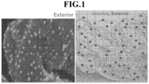
- FIG. 1 is an edited image of a STEM image of an electrode catalyst for a fuel cell according to one embodiment of the present disclosure, and an edited image of a TEM image of an electrode catalyst for a fuel cell according to another embodiment of the present disclosure.
- the STEM image it is an image emphasizing the second metal catalyst particles, and in the case of TEM, the first metal catalyst particles and the second metal catalyst particles are divided.
- metal catalyst particles are present inside and outside the support, respectively, and as described above, the first metal catalyst particles located inside the support pores and the second metal catalyst particles located outside the pores satisfy the content ratio and size ratio, thereby having the effect of improving both performance and durability.
- FIG. 1 is a case where the support has a specific surface area of 300 m 2 /g or more, and as the support has a large specific surface area, it has a high first metal catalyst particle content compared to the case where the support has a specific surface area of less than 300 m 2 /g.
- FIG. 3 is a cross-sectional view schematically showing a membrane-electrode assembly according to the present disclosure.
- the membrane-electrode assembly 100 includes the polymer electrolyte membrane 50 and electrodes 20 and 20' disposed on both surfaces of the polymer electrolyte membrane 50, respectively.
- the electrodes 20, 20' include electrode substrates 40 and 40' and catalyst layers 30 and 30' formed on the surfaces of the electrode substrates 40 and 40', and may further include a microporous layer (not shown) containing conductive fine particles such as carbon powder, carbon black, and the like in order to facilitate diffusion of materials from the electrode substrates 40 and 40' between the electrode substrates 40 and 40' and the catalyst layers 30 and 30'.
- an electrode 20 which is disposed on one surface of the ion exchange membrane 50 to cause an oxidation reaction that generates hydrogen ions and electrons from fuel transferred to the catalyst layer 30 through the electrode substrate 40, is called an anode electrode
- an electrode 20' which is disposed on the other surface of the ion exchange membrane 50 to cause a reduction reaction that generates water from the hydrogen ions supplied through the ion exchange membrane 50 and the oxidizing agent transferred to the catalyst layer 30' through the electrode substrate 40', is called a cathode electrode.
- a porous conductive substrate may be used as the electrode substrates 40 and 40' so that supply of hydrogen or oxygen is smoothly achieved.
- Typical examples thereof may include carbon paper, carbon cloth, carbon felt, or metal cloth (refers to a porous film made of metal cloth in a fiber state or one in which a metal film is formed on the surface of a cloth formed of polymer fibers), but are not limited thereto.
- the electrode substrates 40 and 40' that are water repellent treated with a fluorine-based resin to prevent reactant diffusion efficiency from being reduced by water generated during operation of the fuel cell.
- the fluorine-based resin may include polytetrafluoroethylene, polyvinylidene fluoride, polyhexafluoropropylene, polyperfluoroalkyl vinyl ether, polyperfluorosulfonylfluoride alkoxyvinyl ether, fluorinated ethylene propylene, polychlorotrifluoroethylene, or copolymers thereof.
- the fuel cell according to one embodiment of the present disclosure includes the membrane-electrode assembly and may be, for example, a fuel cell using hydrogen gas as fuel.
- FIG. 4 is a schematic diagram showing the overall configuration of a fuel cell according to one embodiment of the present disclosure.
- the fuel cell 200 includes a fuel supply unit 210 that supplies a mixed fuel in which fuel and water are mixed, a reforming unit 220 that reforms the mixed fuel to generate a reformed gas containing hydrogen gas, a stack 230 in which the reformed gas containing hydrogen gas supplied from the reforming unit 220 causes an electrochemical reaction with an oxidizing agent to generate electrical energy, and an oxidizing agent supply unit 240 supplying the oxidizing agent to the reforming unit 220 and the stack 230.
- a fuel supply unit 210 that supplies a mixed fuel in which fuel and water are mixed
- a reforming unit 220 that reforms the mixed fuel to generate a reformed gas containing hydrogen gas
- a stack 230 in which the reformed gas containing hydrogen gas supplied from the reforming unit 220 causes an electrochemical reaction with an oxidizing agent to generate electrical energy
- an oxidizing agent supply unit 240 supplying the oxidizing agent to the reforming unit 220 and the stack 230.
- the stack 230 is provided with a plurality of unit cells that generate electrical energy by inducing an oxidation/reduction reaction between the reformed gas containing hydrogen gas supplied from the reforming unit 220 and the oxidizing agent supplied from the oxidizing agent supply unit 240.
- Each of the unit cells refers to a unit cell that generates electricity, and includes a membrane-electrode assembly that oxidizes/reduces oxygen in the hydrogen gas-containing reformed gas and the oxidizing agent, and separators (or called bipolar plates, hereinafter referred to as 'separators') for supplying the hydrogen gas-containing reformed gas and the oxidizing agent to the membrane-electrode assembly.
- the separators are disposed on both sides thereof in a state in which the membrane-electrode assembly is placed at the center. At this time, the separators located on the outermost sides of the stack may be particularly called end plates.
- the end plate is provided with a pipe-shaped first supply pipe 231 for injecting reformed gas containing hydrogen gas supplied from the reforming unit 220, and a pipe-shaped second supply pipe 232 for injecting oxygen gas
- the other end plate is provided with a first discharge pipe 233 for discharging to the outside the reformed gas containing the hydrogen gas that is ultimately unreacted and remaining in the plurality of unit cells, and a second discharge pipe 234 for discharging to the outside the oxidizing agent that is ultimately unreacted and remaining in the above-described unit cells.
- Vulcan a surface area of 320 m 2 /g carbon is placed in the above solution and dispersed uniformly.
- the solution is placed in a simple vacuum adsorption device and treated at a vacuum state of 10 kPa for 20 minutes to adsorb the Pt catalyst particle seed into the pores of a carbon support.
- a reducing agent such as ethylene glycol or hexamethylenetetramine is added to the vacuum adsorption-treated solution at an equivalent ratio of 50 to further reduce the solution so that a catalyst is prepared through filtering and drying.
- the process is the same except that acetylene black with a surface area of 120 m 2 /g was used instead of Vulcan carbon with a surface area of 320 m 2 /g used in Example 1 above.
- a catalyst was prepared by dispersing H 2 PtCl 6 as a catalyst precursor and Vulcan carbon as a support in a solvent and reducing it with NaBH 4 using a conventional catalyst preparation method.
- a catalyst was prepared by performing the process in the same manner as in Comparative Example 1 except that acetylene black with a surface area of 120 m 2 /g was used instead of the Vulcan carbon in Comparative Example 1 above using a conventional catalyst preparation method.
- Membrane-electrode assemblies were all manufactured in the same manner except that the catalysts prepared in the above Examples and Comparative Examples were used, respectively.
- FIGS. 5(A) and 5(B) STEM and TEM analyses were performed to find out particle sizes and size distributions of the catalysts prepared in Comparative Example 2 and Example 1, and the results are shown in FIGS. 5(A) and 5(B) , respectively. It can be seen from FIGS. 5(A) and 5(B) that there is no difference in the sizes of the catalyst particles distributed inside and outside the pores in the catalyst of the Comparative Example ( FIG. 5(A) ), whereas catalyst particles with different sizes are distributed inside and outside the pores in the catalyst prepared according to the preparation method of the present disclosure ( FIG. 5(B) ).
- Fuel cells were manufactured using the catalysts of Comparative Examples and Example shown in [Table 1] above (catalysts prepared using a support with a specific surface area of 300 m 2 /g or more), the cell performances were evaluated, and then the results are shown in FIG. 6 .
- fuel cells were manufactured using the catalysts of Comparative Example and Example shown in [Table 2] above (catalysts prepared using a support with a specific surface area of less than 300 m 2 /g), the cell performances were evaluated, and then the results are shown in FIG. 7 . It can be seen from FIGS. 6 and 7 that the catalysts of the Examples according to the present disclosure exhibit higher current densities at the same voltage compared to the catalysts of the Comparative Examples.
- Comparative Example 2 is a catalyst having 80% or more of the metal catalyst particles supported in the pores thereof, and it is confirmed from the previous Evaluation Example 2 that it has poor performance.
- the catalysts of the Examples had its activities increased by optimizing them, the voltage losses are similar to that of Comparative Example 2 as shown in [Table 3] below. This means that the catalysts of the Examples show higher performances than that of the catalyst of Comparative Example 2 and catalyst durability equal to or higher than that of the catalyst of Comparative Example 2.
Landscapes
- Chemical & Material Sciences (AREA)
- Engineering & Computer Science (AREA)
- Chemical Kinetics & Catalysis (AREA)
- General Chemical & Material Sciences (AREA)
- Electrochemistry (AREA)
- Materials Engineering (AREA)
- Manufacturing & Machinery (AREA)
- Thermal Sciences (AREA)
- Metallurgy (AREA)
- Organic Chemistry (AREA)
- Nanotechnology (AREA)
- Inorganic Chemistry (AREA)
- Physics & Mathematics (AREA)
- Mechanical Engineering (AREA)
- Life Sciences & Earth Sciences (AREA)
- Sustainable Development (AREA)
- Sustainable Energy (AREA)
- Catalysts (AREA)
- Inert Electrodes (AREA)
- Fuel Cell (AREA)
Applications Claiming Priority (2)
| Application Number | Priority Date | Filing Date | Title |
|---|---|---|---|
| KR1020210171423A KR102953758B1 (ko) | 2021-12-03 | 2021-12-03 | 연료전지용 촉매, 이의 제조방법 및 이를 포함하는 연료전지 |
| PCT/KR2022/018883 WO2023101333A1 (ko) | 2021-12-03 | 2022-11-25 | 연료전지용 촉매, 이의 제조방법 및 이를 포함하는 연료전지 |
Publications (2)
| Publication Number | Publication Date |
|---|---|
| EP4421922A1 true EP4421922A1 (de) | 2024-08-28 |
| EP4421922A4 EP4421922A4 (de) | 2025-03-26 |
Family
ID=86612593
Family Applications (1)
| Application Number | Title | Priority Date | Filing Date |
|---|---|---|---|
| EP22901691.0A Pending EP4421922A4 (de) | 2021-12-03 | 2022-11-25 | Brennstoffzellenkatalysator, verfahren zur herstellung davon und brennstoffzelle damit |
Country Status (5)
| Country | Link |
|---|---|
| EP (1) | EP4421922A4 (de) |
| JP (1) | JP7795626B2 (de) |
| KR (1) | KR102953758B1 (de) |
| CN (1) | CN118266107A (de) |
| WO (1) | WO2023101333A1 (de) |
Families Citing this family (3)
| Publication number | Priority date | Publication date | Assignee | Title |
|---|---|---|---|---|
| WO2025005623A1 (ko) | 2023-06-28 | 2025-01-02 | 주식회사 엘지에너지솔루션 | 배터리 제조 장치 |
| KR20250098434A (ko) * | 2023-12-22 | 2025-07-01 | 삼성전기주식회사 | 막-전극 어셈블리 |
| WO2025135512A1 (ko) * | 2023-12-22 | 2025-06-26 | 코오롱인더스트리 주식회사 | 수전해셀의 산소발생반응용 촉매 및 이의 제조방법, 및 그를 포함하는 수전해셀용 막-전극 어셈블리 및 수전해셀 |
Family Cites Families (16)
| Publication number | Priority date | Publication date | Assignee | Title |
|---|---|---|---|---|
| JPH11217687A (ja) * | 1997-11-25 | 1999-08-10 | Japan Storage Battery Co Ltd | 固体高分子電解質−触媒複合電極の製造方法 |
| JP2003093874A (ja) * | 2001-09-21 | 2003-04-02 | Mitsubishi Heavy Ind Ltd | コロイド粒子の担持方法およびPt担持カーボン触媒の製造方法 |
| JP2005190724A (ja) * | 2003-12-24 | 2005-07-14 | Nissan Motor Co Ltd | 触媒担持電極、燃料電池用meaおよび燃料電池 |
| KR20080045459A (ko) * | 2006-11-20 | 2008-05-23 | 삼성에스디아이 주식회사 | 연료 전지용 촉매, 이를 포함하는 연료 전지용 막-전극어셈블리 및 이를 포함하는 연료 전지 시스템 |
| US20100285392A1 (en) * | 2007-09-28 | 2010-11-11 | Drexel University | Electrocatalysts for fuel cells |
| JP6415540B2 (ja) * | 2013-04-21 | 2018-10-31 | シェンジェン シェン ルイ グラフィン テクノロジー カンパニー リミテッド | カーボンナノ材料の被覆方法 |
| JP6113836B2 (ja) * | 2013-04-25 | 2017-04-12 | 日産自動車株式会社 | 触媒ならびに当該触媒を用いる電極触媒層、膜電極接合体および燃料電池 |
| WO2016123534A1 (en) * | 2015-01-29 | 2016-08-04 | Basf Corporation | Platinum group metal (pgm) catalysts for automotive emissions treatment |
| WO2016157746A1 (ja) * | 2015-03-27 | 2016-10-06 | パナソニックIpマネジメント株式会社 | 燃料電池用触媒層及び燃料電池 |
| CA3010461C (en) * | 2015-11-30 | 2023-08-29 | University Of Yamanashi | Carbon black, electrode catalyst and fuel cell using same, and method for producing carbon black |
| JP2020028815A (ja) * | 2016-12-20 | 2020-02-27 | パナソニックIpマネジメント株式会社 | 金属担持触媒 |
| KR102613427B1 (ko) | 2018-05-15 | 2023-12-14 | 엔.이. 켐캣 가부시키가이샤 | 전극용 촉매, 가스 확산 전극 형성용 조성물, 가스 확산 전극, 막-전극 접합체 및 연료 전지 스택 |
| JP2019207789A (ja) * | 2018-05-29 | 2019-12-05 | ロベルト・ボッシュ・ゲゼルシャフト・ミト・ベシュレンクテル・ハフツングRobert Bosch Gmbh | 触媒層用インク及び燃料電池の製造方法 |
| WO2020138799A1 (ko) * | 2018-12-26 | 2020-07-02 | 코오롱인더스트리 주식회사 | 촉매, 그 제조방법, 그것을 포함하는 전극, 그것을 포함하는 막-전극 어셈블리, 및 그것을 포함하는 연료 전지 |
| JP7152987B2 (ja) * | 2019-06-07 | 2022-10-13 | 株式会社豊田中央研究所 | 電極触媒 |
| WO2021193256A1 (ja) * | 2020-03-23 | 2021-09-30 | エヌ・イー ケムキャット株式会社 | 電極用触媒、ガス拡散電極形成用組成物、ガス拡散電極、膜・電極接合体、及び、燃料電池スタック |
-
2021
- 2021-12-03 KR KR1020210171423A patent/KR102953758B1/ko active Active
-
2022
- 2022-11-25 JP JP2024529391A patent/JP7795626B2/ja active Active
- 2022-11-25 CN CN202280075979.1A patent/CN118266107A/zh active Pending
- 2022-11-25 WO PCT/KR2022/018883 patent/WO2023101333A1/ko not_active Ceased
- 2022-11-25 EP EP22901691.0A patent/EP4421922A4/de active Pending
Also Published As
| Publication number | Publication date |
|---|---|
| KR102953758B1 (ko) | 2026-04-15 |
| EP4421922A4 (de) | 2025-03-26 |
| JP2024541410A (ja) | 2024-11-08 |
| CN118266107A (zh) | 2024-06-28 |
| KR20230083433A (ko) | 2023-06-12 |
| JP7795626B2 (ja) | 2026-01-07 |
| WO2023101333A1 (ko) | 2023-06-08 |
Similar Documents
| Publication | Publication Date | Title |
|---|---|---|
| EP3493311A1 (de) | Membran-elektroden-anordnung, verfahren zur herstellung davon und brennstoffzelle damit | |
| EP3691006A2 (de) | Radikalfänger, verfahren zu seiner herstellung, membran-elektroden-anordnung damit und brennstoffzelle damit | |
| EP4421922A1 (de) | Brennstoffzellenkatalysator, verfahren zur herstellung davon und brennstoffzelle damit | |
| KR102246839B1 (ko) | 연료 전지용 촉매층 및 그 제조 방법 | |
| JP7498271B2 (ja) | 高耐久性を有する燃料電池用電極、その製造方法、及びそれを含む膜-電極アセンブリー | |
| JP2017035685A (ja) | 炭素担持型pgm系触媒における細孔構造の酸化制御 | |
| JP2007250274A (ja) | 貴金属利用効率を向上させた燃料電池用電極触媒、その製造方法、及びこれを備えた固体高分子型燃料電池 | |
| EP3993111B1 (de) | Brennstoffzellenkatalysator, verfahren zu seiner herstellung und membran-elektroden-anordnung damit | |
| KR20100068028A (ko) | 연료 전지용 촉매층, 및 이의 제조 방법 | |
| EP4270550A1 (de) | Membranelektrodenanordnung und brennstoffzelle damit | |
| JP2010161034A (ja) | 金属触媒担持カーボン粉末の製造方法 | |
| KR102873727B1 (ko) | 선형의 다공성 실리카 나노입자를 포함하는 연료전지용 막-전극 어셈블리 및 이를 포함하는 연료전지 | |
| KR102873733B1 (ko) | 판상의 다공성 실리카를 포함하는 연료전지용 막-전극 어셈블리 및 이를 포함하는 연료전지 | |
| KR102874016B1 (ko) | 연료전지용 막-전극 어셈블리 및 이를 포함하는 연료전지 | |
| KR102884869B1 (ko) | 연료전지용 전극, 이의 제조방법 및 이를 포함하는 연료전지 | |
| EP4668374A1 (de) | Elektrode für eine brennstoffzelle, membranelektrodenanordnung und herstellungsverfahren dafür | |
| KR102844519B1 (ko) | 연료전지용 고분자 전해질막 및 이의 제조방법 | |
| JP2005190712A (ja) | 触媒担持電極、燃料電池用meaおよび燃料電池 | |
| KR102919135B1 (ko) | 연료전지용 고분자 전해질막 및 이를 포함하는 연료전지 | |
| KR20240143440A (ko) | 연료전지용 촉매 및 이의 제조 방법 | |
| KR20230140280A (ko) | 연료전지용 촉매 및 이의 제조 방법 | |
| KR20250157934A (ko) | 연료전지 촉매층용 조성물, 이의 제조방법, 이를 포함하는 연료전지용 전극 및 연료전지 | |
| KR20230173847A (ko) | 연료전지용 전극, 이의 제조방법, 및 이를 포함하는 연료전지 | |
| KR20240040450A (ko) | 연료전지용 강화복합막, 이의 제조방법 및 이를 포함하는 연료전지용 막-전극 어셈블리 | |
| JP2007213919A (ja) | 固体高分子形燃料電池用電極触媒およびその電極触媒を備えた固体高分子形燃料電池 |
Legal Events
| Date | Code | Title | Description |
|---|---|---|---|
| STAA | Information on the status of an ep patent application or granted ep patent |
Free format text: STATUS: THE INTERNATIONAL PUBLICATION HAS BEEN MADE |
|
| PUAI | Public reference made under article 153(3) epc to a published international application that has entered the european phase |
Free format text: ORIGINAL CODE: 0009012 |
|
| STAA | Information on the status of an ep patent application or granted ep patent |
Free format text: STATUS: REQUEST FOR EXAMINATION WAS MADE |
|
| 17P | Request for examination filed |
Effective date: 20240521 |
|
| AK | Designated contracting states |
Kind code of ref document: A1 Designated state(s): AL AT BE BG CH CY CZ DE DK EE ES FI FR GB GR HR HU IE IS IT LI LT LU LV MC ME MK MT NL NO PL PT RO RS SE SI SK SM TR |
|
| DAV | Request for validation of the european patent (deleted) | ||
| DAX | Request for extension of the european patent (deleted) | ||
| A4 | Supplementary search report drawn up and despatched |
Effective date: 20250220 |
|
| RIC1 | Information provided on ipc code assigned before grant |
Ipc: H01M 8/10 20160101ALI20250214BHEP Ipc: H01M 4/90 20060101ALI20250214BHEP Ipc: H01M 4/92 20060101AFI20250214BHEP |
|
| TPAC | Observations filed by third parties |
Free format text: ORIGINAL CODE: EPIDOSNTIPA |