EP4422068A2 - Dalle, système de pavage et procédé de fabrication de dalle - Google Patents
Dalle, système de pavage et procédé de fabrication de dalle Download PDFInfo
- Publication number
- EP4422068A2 EP4422068A2 EP24168070.1A EP24168070A EP4422068A2 EP 4422068 A2 EP4422068 A2 EP 4422068A2 EP 24168070 A EP24168070 A EP 24168070A EP 4422068 A2 EP4422068 A2 EP 4422068A2
- Authority
- EP
- European Patent Office
- Prior art keywords
- module
- layer
- paving
- energy storage
- plane
- Prior art date
- Legal status (The legal status is an assumption and is not a legal conclusion. Google has not performed a legal analysis and makes no representation as to the accuracy of the status listed.)
- Pending
Links
Images

Classifications
-
- H—ELECTRICITY
- H02—GENERATION; CONVERSION OR DISTRIBUTION OF ELECTRIC POWER
- H02S—GENERATION OF ELECTRIC POWER BY CONVERSION OF INFRARED RADIATION, VISIBLE LIGHT OR ULTRAVIOLET LIGHT, e.g. USING PHOTOVOLTAIC [PV] MODULES
- H02S40/00—Components or accessories in combination with PV modules, not provided for in groups H02S10/00 - H02S30/00
- H02S40/30—Electrical components
-
- H—ELECTRICITY
- H05—ELECTRIC TECHNIQUES NOT OTHERWISE PROVIDED FOR
- H05B—ELECTRIC HEATING; ELECTRIC LIGHT SOURCES NOT OTHERWISE PROVIDED FOR; CIRCUIT ARRANGEMENTS FOR ELECTRIC LIGHT SOURCES, IN GENERAL
- H05B3/00—Ohmic-resistance heating
- H05B3/0033—Heating devices using lamps
- H05B3/0038—Heating devices using lamps for industrial applications
-
- H—ELECTRICITY
- H05—ELECTRIC TECHNIQUES NOT OTHERWISE PROVIDED FOR
- H05B—ELECTRIC HEATING; ELECTRIC LIGHT SOURCES NOT OTHERWISE PROVIDED FOR; CIRCUIT ARRANGEMENTS FOR ELECTRIC LIGHT SOURCES, IN GENERAL
- H05B3/00—Ohmic-resistance heating
- H05B3/20—Heating elements having extended surface area substantially in a two-dimensional [2D] plane, e.g. plate-heater
- H05B3/34—Heating elements having extended surface area substantially in a two-dimensional [2D] plane, e.g. plate-heater flexible, e.g. heating nets or webs
-
- E—FIXED CONSTRUCTIONS
- E01—CONSTRUCTION OF ROADS, RAILWAYS, OR BRIDGES
- E01C—CONSTRUCTION OF, OR SURFACES FOR, ROADS, SPORTS GROUNDS, OR THE LIKE; MACHINES OR AUXILIARY TOOLS FOR CONSTRUCTION OR REPAIR
- E01C11/00—Details of pavings
- E01C11/24—Methods or arrangements for preventing slipperiness or protecting against influences of the weather
- E01C11/26—Permanently installed heating or blowing devices ; Mounting thereof
- E01C11/265—Embedded electrical heating elements ; Mounting thereof
-
- E—FIXED CONSTRUCTIONS
- E01—CONSTRUCTION OF ROADS, RAILWAYS, OR BRIDGES
- E01C—CONSTRUCTION OF, OR SURFACES FOR, ROADS, SPORTS GROUNDS, OR THE LIKE; MACHINES OR AUXILIARY TOOLS FOR CONSTRUCTION OR REPAIR
- E01C17/00—Pavement lights, i.e. translucent constructions forming part of the surface
-
- E—FIXED CONSTRUCTIONS
- E01—CONSTRUCTION OF ROADS, RAILWAYS, OR BRIDGES
- E01C—CONSTRUCTION OF, OR SURFACES FOR, ROADS, SPORTS GROUNDS, OR THE LIKE; MACHINES OR AUXILIARY TOOLS FOR CONSTRUCTION OR REPAIR
- E01C5/00—Pavings made of prefabricated single units
- E01C5/22—Pavings made of prefabricated single units made of units composed of a mixture of materials covered by two or more of groups E01C5/008, E01C5/02 - E01C5/20 except embedded reinforcing materials
-
- H—ELECTRICITY
- H02—GENERATION; CONVERSION OR DISTRIBUTION OF ELECTRIC POWER
- H02S—GENERATION OF ELECTRIC POWER BY CONVERSION OF INFRARED RADIATION, VISIBLE LIGHT OR ULTRAVIOLET LIGHT, e.g. USING PHOTOVOLTAIC [PV] MODULES
- H02S20/00—Supporting structures for PV modules
- H02S20/20—Supporting structures directly fixed to an immovable object
- H02S20/22—Supporting structures directly fixed to an immovable object specially adapted for buildings
- H02S20/26—Building materials integrated with PV modules, e.g. façade elements
-
- H—ELECTRICITY
- H05—ELECTRIC TECHNIQUES NOT OTHERWISE PROVIDED FOR
- H05B—ELECTRIC HEATING; ELECTRIC LIGHT SOURCES NOT OTHERWISE PROVIDED FOR; CIRCUIT ARRANGEMENTS FOR ELECTRIC LIGHT SOURCES, IN GENERAL
- H05B2203/00—Aspects relating to Ohmic resistive heating covered by group H05B3/00
- H05B2203/013—Heaters using resistive films or coatings
-
- H—ELECTRICITY
- H05—ELECTRIC TECHNIQUES NOT OTHERWISE PROVIDED FOR
- H05B—ELECTRIC HEATING; ELECTRIC LIGHT SOURCES NOT OTHERWISE PROVIDED FOR; CIRCUIT ARRANGEMENTS FOR ELECTRIC LIGHT SOURCES, IN GENERAL
- H05B2203/00—Aspects relating to Ohmic resistive heating covered by group H05B3/00
- H05B2203/017—Manufacturing methods or apparatus for heaters
-
- H—ELECTRICITY
- H05—ELECTRIC TECHNIQUES NOT OTHERWISE PROVIDED FOR
- H05B—ELECTRIC HEATING; ELECTRIC LIGHT SOURCES NOT OTHERWISE PROVIDED FOR; CIRCUIT ARRANGEMENTS FOR ELECTRIC LIGHT SOURCES, IN GENERAL
- H05B2203/00—Aspects relating to Ohmic resistive heating covered by group H05B3/00
- H05B2203/026—Heaters specially adapted for floor heating
-
- H—ELECTRICITY
- H05—ELECTRIC TECHNIQUES NOT OTHERWISE PROVIDED FOR
- H05B—ELECTRIC HEATING; ELECTRIC LIGHT SOURCES NOT OTHERWISE PROVIDED FOR; CIRCUIT ARRANGEMENTS FOR ELECTRIC LIGHT SOURCES, IN GENERAL
- H05B2214/00—Aspects relating to resistive heating, induction heating and heating using microwaves, covered by groups H05B3/00, H05B6/00
- H05B2214/02—Heaters specially designed for de-icing or protection against icing
-
- Y—GENERAL TAGGING OF NEW TECHNOLOGICAL DEVELOPMENTS; GENERAL TAGGING OF CROSS-SECTIONAL TECHNOLOGIES SPANNING OVER SEVERAL SECTIONS OF THE IPC; TECHNICAL SUBJECTS COVERED BY FORMER USPC CROSS-REFERENCE ART COLLECTIONS [XRACs] AND DIGESTS
- Y02—TECHNOLOGIES OR APPLICATIONS FOR MITIGATION OR ADAPTATION AGAINST CLIMATE CHANGE
- Y02B—CLIMATE CHANGE MITIGATION TECHNOLOGIES RELATED TO BUILDINGS, e.g. HOUSING, HOUSE APPLIANCES OR RELATED END-USER APPLICATIONS
- Y02B10/00—Integration of renewable energy sources in buildings
- Y02B10/10—Photovoltaic [PV]
-
- Y—GENERAL TAGGING OF NEW TECHNOLOGICAL DEVELOPMENTS; GENERAL TAGGING OF CROSS-SECTIONAL TECHNOLOGIES SPANNING OVER SEVERAL SECTIONS OF THE IPC; TECHNICAL SUBJECTS COVERED BY FORMER USPC CROSS-REFERENCE ART COLLECTIONS [XRACs] AND DIGESTS
- Y02—TECHNOLOGIES OR APPLICATIONS FOR MITIGATION OR ADAPTATION AGAINST CLIMATE CHANGE
- Y02E—REDUCTION OF GREENHOUSE GAS [GHG] EMISSIONS, RELATED TO ENERGY GENERATION, TRANSMISSION OR DISTRIBUTION
- Y02E10/00—Energy generation through renewable energy sources
- Y02E10/50—Photovoltaic [PV] energy
Definitions
- the invention relates to a paving slab for paving a traffic area, comprising a slab body with at least one recess, a module arranged in the at least one recess, the module extending flatly along a module plane, and at least one flat cover element aligned along the module plane and at least partially translucent for protecting the at least one module.
- the invention further relates to a paving system with a plurality of paving slabs and a method for producing the paving slab.
- the object of the invention is to create cost-effective, efficient and versatile components for traffic routes with additional functions that have an extended service life. Furthermore, the object of the invention is to provide a cost-effective and reliable manufacturing process for the components.
- the present invention provides a paving slab according to claim 1, which solves the technical problem.
- the problem is also solved by a paving system according to claim 10 and a method for producing the paving slab according to claim 12.
- Advantageous embodiments emerge from the dependent claims.
- the invention relates to a paving slab for paving a traffic area, wherein the paving slab comprises a slab body with at least one recess, wherein a module is arranged in the at least one recess, wherein the module extends flatly along a module plane.
- a length and a width orthogonal to the length of the module along the module plane are each significantly greater than a height of the module perpendicular to the module plane.
- the length and/or the width are at least ten times as large, in particular at least one hundred times as large, as the height.
- the module can be essentially cuboid-shaped.
- the module preferably comprises at least one flat heating layer aligned along the module plane for heating an area surrounding the module.
- the heating layer has a thickness of 6 ⁇ m to 60 ⁇ m perpendicular to the module plane.
- the heating layer contains, for example, carbon nanotubes, organic solutions, emulsifiers, thickeners, thinners, conditioners, viscosity agents, adhesives and/or anti-oxidants.
- the materials used as a heating layer advantageously convert almost 100% of the electrical energy fed in via the heating voltage into heat.
- the heating layer is preferably designed for heating up to a maximum temperature of 523 K.
- the heating layer comprises, for example, a number of conductor tracks that are embedded perpendicular to the module plane between two electrical insulation layers.
- the heating layer can, for example, be constructed as shown in DE 203 19 024 U1 described surface heating element or the one in WO93/23968 A1 described resistance heating unit ("resistor heating unit 19").
- resistor heating unit 19 The corresponding paragraphs [0016] to [0026] of DE 203 19 024 U1 and Figures 7a and 7b with their description on page 12 of WO93/23968 A1 are incorporated herein by reference.
- the module preferably comprises at least one planar energy storage layer aligned along the module plane for storing electrical energy, wherein a planar thermal insulation layer aligned along the module plane is preferably arranged between the heating layer and the energy storage layer.
- the energy storage layer advantageously allows the module to be operated independently of an external energy supply. Furthermore, the energy storage layer can be charged when there is a particularly large amount of inexpensive electrical energy available, for example from wind turbines or photovoltaic systems, and the stored energy can be used at a later time when less electrical energy is available. This minimizes the operating costs of the module and compensates for fluctuations in the energy supply without the need for an additional, expensive and space-consuming energy storage device.
- the thermal insulation layer protects the energy storage layer from overheating by the heating layer, especially when the heating layer is operated at a high temperature to heat a large room with a compact module.
- the module preferably comprises at least one flat photovoltaic layer aligned along the module plane for generating electrical energy.
- the heating layer can advantageously be supplied with energy without an external energy supply.
- the module can still comprise a connection for an external energy supply in order to supply the heating layer and/or to deliver energy generated by the photovoltaic layer to the external energy supply.
- the module comprises at least one energy storage layer and at least one photovoltaic layer.
- the energy obtained from the photovoltaic layer can be temporarily stored in the energy storage layer and used at a later time, in particular while the photovoltaic layer is not provides sufficient power to operate the heating layer, can be used to operate the heating layer.
- the module preferably comprises at least one flat, preferably flexible, luminous layer aligned along the module plane for illuminating an environment of the module, wherein the luminous layer comprises a plurality of material layers aligned along the module plane with mutually different material compositions.
- the area surrounding the module can be illuminated without the need for separate lights, so that, for example, the heating and lighting of the area can be ensured with particularly low investment and space requirements.
- the at least one luminous layer, the at least one heating layer and the at least one energy storage layer and/or the at least one photovoltaic layer, in particular all of the layers mentioned, preferably each comprise a plurality of material layers aligned along the module plane with different material compositions from one another.
- the layers can be produced particularly easily, quickly and cost-effectively, for example using a printing process, in particular a screen printing process.
- the material layers each extend over an entire surface of the module along the module plane. This allows the material layers to be manufactured in a particularly simple manner.
- the photovoltaic layer is preferably designed as a low-light-condition solar module and/or as a thin-film solar module, comprising, for example, amorphous silicon (a-Si:H), microcrystalline silicon ( ⁇ c-Si:H), gallium arsenide (GaAs), cadmium telluride (CdTe) or copper-indium-(gallium)-sulfur-selenium compounds as photoactive material.
- a-Si:H amorphous silicon
- ⁇ c-Si:H microcrystalline silicon
- GaAs gallium arsenide
- CdTe cadmium telluride
- copper-indium-(gallium)-sulfur-selenium compounds as photoactive material.
- the photovoltaic layer comprises at least one translucent front electrode layer perpendicular to the module plane and/or thereafter directly or indirectly at least one carrier structure layer for mechanical stabilization and/or thereafter directly or indirectly at least one photoactive layer with a photoactive material and/or thereafter directly or indirectly at least one transport layer and/or thereafter, directly or indirectly, at least one baking electrode layer and/or thereafter, directly or indirectly, at least one encapsulation layer, wherein a voltage can advantageously be applied between the transparent front electrode layer and the baking electrode layer.
- the transport layer and the carrier structure layer are omitted. This is advantageous because it allows a particularly thin design. However, this is disadvantageous because the transport layer has particularly good properties for maintaining charge separation. It is also conceivable that the photoactive material loses its effect without a stabilizing carrier structure layer. For example, glasses, PMMA, metal foils, plastic foils are conceivable for the carrier structure layer. Negative and positive designs made of organic and/or inorganic materials are conceivable for the transport layer. Their task is to transport the electrons better.
- the encapsulation layer is advantageously designed as an electrical insulation layer, for example made of a plastic. If the photovoltaic layer is adjacent to another layer that has an encapsulation layer on a side facing the photovoltaic layer, the photovoltaic layer can advantageously be designed without an encapsulation layer on the side facing the other layer. This enables particularly material-saving and rapid production.
- the encapsulation layer adjacent to the back electrode advantageously has a thickness of between 500 nm and 250 ⁇ m.
- the back electrode layer advantageously has a thickness of between 100 nm and 15 ⁇ m.
- the transport layer advantageously has a thickness of between 50 nm and 5 ⁇ m.
- the photoactive layer advantageously has a thickness of between 50 nm and 5 ⁇ m.
- the carrier structure layer advantageously has a thickness of between 100 nm and 5 ⁇ m.
- the front electrode layer advantageously has a thickness of between 100 nm and 5 ⁇ m.
- the encapsulation layer adjacent to the front electrode advantageously has a thickness of between 20 ⁇ m and 250 ⁇ m.
- the energy storage layer is preferably resistant to a temperature of at least 60 °C, in particular at least 85 °C, preferably at least 120 °C. Due to this increased heat resistance compared to conventional energy storage devices, for example lithium-ion batteries, the energy storage layer can advantageously be combined with the heating layer in a compact module without the energy storage layer being damaged by heat emitted by the heating layer.
- the energy storage layer can be designed to be liquid-free, contain sodium ions and in particular no lithium ions as mobile charge carriers and/or be designed to be free of defects (so-called "pinholes").
- pinholes defects
- the energy storage layer preferably comprises at least two electrode layers, at least one separator layer with an electrolyte in between and at least one encapsulation layer on each of the outer sides.
- the encapsulation layer is advantageously designed as an electrical insulation layer, for example made of a plastic.
- the energy storage layer is adjacent to another layer that has an encapsulation layer on a side facing the energy storage layer, the energy storage layer can advantageously be designed without an encapsulation layer on the side facing the other layer. This enables particularly material-saving and rapid production.
- At least one electrode layer preferably comprises a metal, in particular lithium or sodium, carbon, in particular in the form of activated carbon, activated carbon fiber, carbide-derived carbon, carbon aerogel, graphite, graphene and/or carbon nanotubes, a transition metal oxide, for example an oxide of ruthenium, iridium, iron and/or manganese, and/or an electrically conductive polymer, for example polypyrrole, polyaniline, pentacene or polythiophene.
- a metal in particular lithium or sodium
- carbon in particular in the form of activated carbon, activated carbon fiber, carbide-derived carbon, carbon aerogel, graphite, graphene and/or carbon nanotubes, a transition metal oxide, for example an oxide of ruthenium, iridium, iron and/or manganese, and/or an electrically conductive polymer, for example polypyrrole, polyaniline, pentacene or polythiophene.
- the separator layer comprises, for example, a porous plastic and/or a porous ceramic.
- the electrolyte comprises, for example, an aqueous electrolyte solution, an organic electrolyte solution, an ionic liquid, a super-concentrated electrolyte, an ion-conductive polymer and/or an ion-conductive ceramic, e.g. Ag 4 Rbl 5 for the charge transport of Ag + ions, a closo-borane for the charge transport of Na + ions or a Lil/Al 2 O 3 mixture for the charge transport of Li + ions.
- the energy storage layer is preferably designed as a solid-state accumulator, for example as a lithium-air solid-state accumulator, or as a supercapacitor.
- a thickness perpendicular to the module plane is advantageously 20 ⁇ m to 250 ⁇ m for the encapsulation layers, advantageously 3 ⁇ m to 250 ⁇ m for the electrode layers and/or advantageously 0.5 ⁇ m to 250 ⁇ m for the separator layer.
- the at least one luminous layer, the at least one heating layer, the at least one energy storage layer and/or the at least one photovoltaic layer are preferably arranged one above the other perpendicular to the module plane. This makes it particularly easy to apply the layers one after the other to a substrate, for example using a printing process, in particular a screen printing process.
- a layer thickness of the at least one luminous layer, the at least one heating layer, the at least one energy storage layer and/or the at least one photovoltaic layer perpendicular to the module plane is preferably in each case from 0.1 ⁇ m to 1 mm, preferably from 0.5 ⁇ m to 0.2 mm.
- the at least one luminous layer, the at least one heating layer, the at least one energy storage layer, the at least one thermal insulation layer and/or the at least one photovoltaic layer, preferably the entire module, is preferably designed to be flexible. This advantageously reduces the risk of damage due to mechanical stress. This distinguishes the module according to the invention from known photovoltaic modules or luminous modules, which are rigid so that they can easily be damaged by mechanical stress, in particular by vibrations, when used in a traffic route.
- the insulating layer preferably comprises a calcium silicate, chitosan and a heat-resistant binder. Using the above ingredients, a particularly thin and flexible insulating layer with low thermal conductivity can be produced in a simple manner, for example by screen printing.
- the insulating layer may comprise PET, PVC, organic solutions, emulsifiers, thickeners, thinners, conditioners, viscosifiers, adhesives and/or anti-oxidants.
- the insulating layer preferably has a layer thickness of 10 ⁇ m to 500 ⁇ m, preferably 40 ⁇ m to 100 ⁇ m.
- the photovoltaic layer is designed as a layer that is at least partially translucent, in particular transparent, in particular such that perpendicular to the module plane the at least one The luminescent layer and the photovoltaic layer are arranged one above the other. If the photovoltaic layer is translucent, it can be used as a permeable layer for the light from the luminescent layer when the incoming light decreases, for example at dusk.
- a through-connection between the photovoltaic layer and an energy storage layer through the luminescent layer enables the electrical energy generated in the photovoltaic layer to be transferred to the energy storage layer. Further contact advantageously enables the energy stored in the energy storage layer to be released to supply the luminescent layer.
- the at least one photovoltaic layer is opaque. This is particularly advantageous because photovoltaic layers that are not transparent have a higher efficiency than transparent photovoltaic layers.
- the photovoltaic layer and the luminescent layer can be arranged next to each other or inside each other along the module plane so that they do not hinder each other when absorbing or emitting light perpendicular to the module plane.
- the disadvantage here is that the entire surface of the module is not available for the photovoltaic layer and the luminescent layer.
- the advantage is that an energy storage layer can be arranged both adjacent to the photovoltaic layer and adjacent to the luminescent layer, which enables particularly efficient energy transport.
- an induction layer of the module and/or the at least one energy storage layer is at least partially translucent, in particular transparent.
- These configurations allow light to be absorbed or emitted by the luminescent layer or photovoltaic layer through the energy storage layer and/or induction layer, so that the layer sequence can be optimized, for example, for the simplest possible production or efficient connection of the individual layers.
- the module preferably comprises at least one, preferably flexible, carrier element extending flatly along the module plane, onto which the at least one luminous layer, the at least one heating layer, the at least one energy storage layer and/or the at least one photovoltaic layer are applied, for example using a screen printing process.
- the layers can be applied to one or both sides of the surface of the carrier element. Applying them to one side allows for particularly fast production. Applying them to both sides ensures particularly high mechanical stability due to the arrangement of the carrier element between the layers.
- the heating layer can be applied to one surface side and an energy storage layer to the opposite surface side of the carrier element, whereby the carrier element advantageously contributes to the thermal insulation of the energy storage layer from the heating layer.
- the carrier element comprises, for example, a plastic, in particular PET, a polyimide, PMMA and/or a polycarbonate, and/or a metal.
- the carrier element is advantageously rectangular.
- the carrier element is preferably designed as a film and is flexible. This allows the entire module to be designed to be thin and flexible.
- the carrier element comprises, for example, a plastic film and/or metal film with a thickness of 1 ⁇ m to 1 mm, in particular 5 ⁇ m to 50 ⁇ m.
- the carrier element comprises, in particular, a PET film with a thickness of 5 ⁇ m to 50 ⁇ m.
- the carrier element advantageously provides the module with sufficient mechanical stability so that the module is not damaged during its manufacture, further processing or use.
- the module preferably comprises at least one, preferably flexible, encapsulation layer for protecting at least the at least one luminous layer, the at least one heating layer, the at least one energy storage layer and/or the at least one photovoltaic layer from environmental influences, in particular from moisture and/or mechanical stress.
- the encapsulation layer comprises, for example, a plastic, in particular PET, a polyimide, PMMA and/or a polycarbonate.
- the encapsulation layer is preferably applied to the carrier element by screen printing.
- the carrier element and/or the encapsulation layer is preferably translucent, in particular transparent, at least in sections. This is particularly advantageous in order to be permeable to the light absorbed by the at least one photovoltaic layer or light emitted by a luminescent layer.
- the module preferably comprises at least one flat, preferably flexible, induction layer aligned along the module plane for inductively charging an electronic device arranged on the module, preferably a Electric vehicle, wherein the at least one induction layer comprises a plurality of material layers aligned along the module plane with mutually different material compositions.
- the induction layer allows the electronic device to be charged wirelessly, meaning the module provides additional functionality without taking up significantly more space or requiring additional installation work.
- the module is installed in the floor of a parking lot, the previously very impractical charging of electric vehicles can be made much easier with the help of the module's induction layer.
- the module includes a photovoltaic layer
- this has the additional advantage that the additional costs of a paving slab with a module compared to a standard paving slab can be offset or even over-compensated by selling or using the electrical energy generated.
- the ecological disadvantages of paved traffic areas, in particular the soil sealing they cause can be at least partially offset by generating renewable energy.
- the slab body can have any shape and/or size known for standard paving slabs; in particular, the slab body can be essentially cuboid-shaped.
- the slab body can comprise any material known for standard paving slabs.
- the slab body can comprise an artificial stone and/or a plastic, preferably a recycled composite material.
- Recycled composite materials include also plastics that are obtained from recyclable household waste, especially packaging waste.
- Recycled composite materials from packaging waste have already been used, for example, for flood protection walls ( DE 20 2004 008 412 U1 , EN 20 2004 012 013 U1 ), roadway elements ( DE 9 406 259 U1 ) or noise barriers ( EN 10 2007 053 614 A1 ) is used.
- the paving slab preferably comprises at least one flat cover element which is aligned along the module plane of the at least one module and is at least partially translucent, in particular transparent, for protecting the at least one module, wherein the at least one module is enclosed by the slab body and the at least one cover element in an at least liquid-tight manner.
- the cover element advantageously protects the module from mechanical stress and from foreign substances, in particular from rainwater and substances suspended or dissolved in it, such as salt.
- the cover element thus increases the service life of the module.
- the cover element can, for example, comprise a plastic that is cast onto the module in the recess, or consist of this plastic. By casting it with plastic, the module can be enclosed in a particularly reliable and permanent liquid-tight manner.
- the cover element can, for example, comprise a glass plate arranged on the module in the recess, which is connected to the plate body in a liquid-tight manner using a sealant, in particular a sealing ring.
- the glass plate is more resistant to light-induced aging and mechanical abrasion than a cover element made of plastic and thus permanently ensures high light transmission, which enables efficient operation of the photovoltaic layer and the luminous layer of the module.
- the paving slab preferably comprises at least one sensor for automatically controlling the at least one heating layer and/or the at least one luminous layer of the module, wherein the at least one sensor comprises a temperature sensor, a brightness sensor and/or a presence sensor, preferably a radar sensor and/or infrared sensor.
- the at least one sensor comprises a temperature sensor, a brightness sensor and/or a presence sensor, preferably a radar sensor and/or infrared sensor.
- the heating layer can advantageously be controlled automatically so that icing of the paving slab is prevented with minimal energy consumption.
- the luminescent layer can advantageously be activated automatically exactly when low ambient brightness requires it, thus minimizing energy consumption.
- the luminous layer can be automatically activated precisely when the paving slab is walked on or driven over, thus minimizing energy consumption.
- a radar sensor and an infrared sensor have the advantage over other presence sensors, such as pressure sensors, that they do not contain any moving parts and are therefore particularly durable. In particular, a liquid-tight enclosure of the module is not endangered by the movement of moving parts.
- the invention relates to a paving system for paving a traffic area, comprising a plurality of paving slabs according to the invention and at least one bus cable for central energy supply and/or control of at least the heating layers and/or luminous layers of the paving slabs, wherein each of the paving slabs comprises at least one bus plug for connecting the heating layers and/or luminous layers of the paving slabs to the at least one bus cable.
- the paving slabs and the bus cable are preferably designed for power supply and/or control with a low-voltage system, in particular with a maximum voltage of 60 V.
- a low-voltage system has the advantage that it can be safely installed by people without special knowledge in the field of electrical installation, for example pavers.
- the control can advantageously be carried out by a central control device, in particular with a number of central sensors and/or automatically. This has the advantage that not every single paving slab has to be equipped with sensors and/or a control device, which reduces installation costs.
- the central sensors can, for example, be designed as previously described for the sensors of the paving slab according to the invention.
- the bus connector is preferably designed to be protected against polarity reversal to simplify installation.
- the bus connector is preferably lockable to prevent it from accidentally coming loose from the paving slab, for example due to vibrations when the paving slab is driven over.
- the bus connector is preferably designed to be waterproof to protect against corrosion and short circuits.
- the carrier element can in particular be designed as described above.
- the layers can in particular be designed as described above.
- all layers of the module are produced by screen printing.
- electrical connections between the layers and/or within the layers of the module that are necessary for operating the module can also be produced by screen printing.
- the entire module or the entire module except for the carrier element is produced by screen printing.
- the materials for producing the layers can be provided as pastes, which are applied using a screen printing process.
- a particular advantage of the screen printing process is that the layers can be applied very quickly and inexpensively. Speeds of up to 400 m 2 per hour are possible with an appropriate printing machine.
- Enclosing the module preferably involves casting the cover element made of a plastic onto the module in the recess.
- a reliable and long-lasting seal of the module against environmental influences is achieved particularly easily and quickly.
- the casting of the cover element is preferably carried out under high frequency excitation of the plastic.
- high frequency vibrations for example with a frequency of 1 MHz to 1 THz, in particular 10 MHz to 1 GHz, possible gas inclusions that could lead to Leaks or a reduced mechanical load-bearing capacity of the cover element are expelled from the liquid plastic.
- the method preferably comprises hardening at least one layer of the module by irradiating the layer with infrared light, preferably during an irradiation time of 0.1 s to 100 s, particularly preferably 1 s to 10 s. Hardening makes it possible to apply further layers directly to the hardened layer without additional waiting time and without damaging the hardened layer.
- the module can thus be manufactured particularly quickly and inexpensively.
- Irradiation with infrared light has the advantage that the layers can be heated and hardened particularly quickly and without contact.
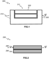
- Figure 1 shows a schematic sectional view perpendicular to the module plane HE of a paving slab 300 according to the invention.
- the paving slab 300 comprises a slab body 310 with a recess 311, wherein a module 200 according to the invention is arranged in the recess 311.
- the paving slab 300 comprises a flat cover element 320 which is aligned along the module plane HE of the module 200 and is at least partially translucent for protecting the module 200, wherein the module 200 is enclosed in a liquid-tight manner by the slab body 310 and the at least one cover element 320.
- the cover element 320 comprises, for example, a transparent plastic which is cast with the plate body 310.
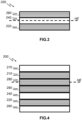
- FIG. 2 shows a schematic sectional view perpendicular to the module plane HE of a module 200 according to the invention.
- the module 200 extends flat along the module plane HE and comprises a flat heating layer 290 aligned along the module plane HE for heating an environment of the module 200 and a flat photovoltaic layer 280 aligned along the module plane HE for generating electrical energy.
- the heating layer 290 and the photovoltaic layer 280 each comprise a plurality of material layers aligned along the module plane HE (shown by hatching) with different material compositions.
- a possible structure of the heating layer 290 and the photovoltaic layer 280 is shown in the Figures 7 and 9 shown.
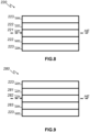
- FIG. 3 shows a schematic sectional view perpendicular to the module plane HE of a module 200 according to the invention.
- the module 200 extends flat along the module plane HE and comprises a flat heating layer 290 aligned along the module plane HE for heating an environment of the module 200 and a flat energy storage layer 220 aligned along the module plane HE for storing electrical energy, wherein a flat thermal insulation layer 240 aligned along the module plane HE is arranged between the heating layer 290 and the energy storage layer 220.
- the insulating layer 240 comprises, for example, a calcium silicate, chitosan and a heat-resistant binder and has, for example, a layer thickness perpendicular to the module plane HE of 40 ⁇ m to 100 ⁇ m.
- the heating layer 290 and the energy storage layer 220 each comprise a plurality of material layers aligned along the module plane HE (shown by hatching) with different material compositions.
- a possible structure of the heating layer 290 and the energy storage layer 220 is shown in the Figures 7 and 8 shown.
- Figure 4 shows a schematic sectional view perpendicular to the module plane HE of another module 200 according to the invention.
- module 200 includes the following additional layers:
- the module 200 comprises a planar luminous layer 210 aligned along the module plane HE for illuminating an environment of the module 200, wherein the luminous layer 210 comprises a plurality of material layers aligned along the module plane HE (shown by hatching) with mutually different material compositions.
- the luminescent layer 210 is arranged, for example, on the side of the photovoltaic layer 280 facing away from the heating layer 290.
- a possible structure of the luminescent layer 210 is shown in Figure 5 shown.
- the module 200 comprises a planar energy storage layer 220 aligned along the module plane HE for storing electrical energy, wherein a planar thermal insulation layer 240 aligned along the module plane HE is arranged between the heating layer 290 and the energy storage layer 220.
- the energy storage layer 220 is arranged, for example, on the side of the heating layer 290 facing away from the photovoltaic layer 280.
- the insulating layer 240 is, for example, as shown in Figure 3 described.
- the heating layer 290 and the energy storage layer 220 each comprise a plurality of material layers aligned along the module plane HE (shown by hatching) with different material compositions.
- a possible structure of the heating layer 290 and the energy storage layer 220 is shown in the Figures 7 and 8 shown.
- the module 200 comprises a carrier element 260 extending flatly along the module plane HE, for example a PET film, to which at least the layers of the module 200 are applied, for example by screen printing.
- a carrier element 260 extending flatly along the module plane HE, for example a PET film, to which at least the layers of the module 200 are applied, for example by screen printing.
- the module 200 comprises an encapsulation layer 270 for protecting the remaining layers of the module 200 from environmental influences, wherein, for example, the encapsulation layer 270 is at least partially translucent.
- the encapsulation layer 270 consists, for example, of a transparent plastic, in particular of PET.
- the order of the layers of the module 200 is, for example, perpendicular to the module plane HE: carrier element 260, energy storage layer 220, insulating layer 240, heating layer 290, photovoltaic layer 280, luminescent layer 210, encapsulation layer 270.
- Figure 5 shows a schematic sectional view perpendicular to the module plane HE of a luminous layer 210 of a module 200 according to the invention, designed for example as an OLED, comprising several material layers aligned along the module plane HE with mutually different material compositions.
- the illustrated luminescent layer 210 comprises, for example, an anode layer 211, consisting for example of indium tin oxide, and an adjoining hole-conducting layer 212.
- the hole-conducting layer 212 is followed by a dye layer 213, which contains an organic dye.
- the illustrated luminescent layer 210 is terminated by a cathode layer 214, consisting of a metal, such as calcium or barium.
- the dye can comprise, for example, a derivative of poly(p-phenylene vinyl).
- Figure 6 shows a schematic sectional view perpendicular to the module plane HE of an induction layer 230 of a module 200 according to the invention, comprising several material layers aligned along the module plane HE with mutually different material compositions.
- the illustrated induction layer 230 comprises, for example, an induction coil 231, for example made of a metal, and an electrically insulating sheath 232, for example made of a plastic, at least perpendicular to the module plane HE above and below the induction coil 231.
- Figure 7 shows a schematic sectional view perpendicular to the module plane HE of a heating layer 290 of a module 200 according to the invention, comprising several material layers aligned along the module plane HE with mutually different material compositions.
- the illustrated heating layer 290 comprises, for example, a number of conductor tracks 291, for example made of a metal, and in each case an electrically insulating insulating layer 292, for example made of a plastic, perpendicular to the module plane HE above and below the conductor tracks 291.
- Figure 8 shows a schematic sectional view perpendicular to the module plane HE of an energy storage layer 220 of a module 200 according to the invention, comprising several material layers aligned along the module plane HE with mutually different material compositions.
- the energy storage layer 220 which is designed as a solid-state accumulator, for example, comprises two electrode layers 222, a separator layer 221 with an electrolyte in between and an encapsulation layer 223 on each of the outer sides designed as an electrical insulator, for example made of a plastic.
- the electrode layer 222 comprises, for example, carbon and/or an electrically conductive polymer.
- the encapsulation layers 223 comprise, for example, an electrically insulating plastic.
- the separator layer 221 comprises, for example, a porous plastic that conducts ions as a polymer electrolyte.
- Figure 9 shows a schematic sectional view perpendicular to the module plane HE of a photovoltaic layer 280 of a module 200 according to the invention, comprising several material layers aligned along the module plane HE with mutually different material compositions.
- the photovoltaic layer 280 is designed, for example, as a thin-film solar cell, comprising, for example, microcrystalline silicon ( ⁇ c-Si:H) as a photoactive material.
- ⁇ c-Si:H microcrystalline silicon
- the photovoltaic layer 280 comprises, for example, a translucent front electrode layer 281 perpendicular to the module plane HE, one above the other, and then a photoactive layer 282 with the photoactive material and then a back electrode layer 283.
- the end of the photovoltaic layer 280 perpendicular to the module plane HE is formed, for example, by an electrically insulating encapsulation layer 223, for example made of a plastic.
- ⁇ b>List of reference symbols ⁇ /b> 200 module 260 Support element 210 Luminescent layer 270 Encapsulation layer 211 Anode position 280 Photovoltaic layer 212 Perforated line layer 281 Front electrode position 213 Dye layer 282 Photoactive layer 214 Cathode layer 283 Baking electrode position 220 Energy storage layer 290 Heating layer 221 Separator layer 291 Conductor track 222 Electrode position 292 Insulation layer 223 Encapsulation layer 300 Paving slab 230 Induction layer 310 Plate body 231 Induction coil 311 Recess 232 Sheathing 320 Cover element 240 Insulating layer HE Module level Further embodiments of the present invention are set out in the following items: [Item 1] Paving slab (300) for paving a traffic area, the paving slab (300) comprising a plate body (310)
- Paving slab (300) according to item 1 characterized in that a. the module (200) comprises at least one flat and flexible heating layer (290) aligned along the module plane (HE) for heating an environment of the module (200), b. wherein the at least one heating layer (290) is applied to the carrier element (260) by screen printing, and c. wherein the at least one heating layer (290) comprises a plurality of material layers aligned along the module plane (HE) with mutually different material compositions.
- Paving slab (300) according to item 1 or 2 characterized in that the module (200) comprises at least one flat and flexible energy storage layer (220) aligned along the module plane (HE) for storing electrical energy, b.
- the at least one energy storage layer (220) is applied to the carrier element (260) by screen printing, and c. wherein the at least one energy storage layer (220) comprises a plurality of material layers aligned along the module plane (HE) with mutually different material compositions.
- Paving slab (300) according to item 4 characterized in that the insulating layer (240) of the module (200) comprises a calcium silicate, chitosan and a heat-resistant binder.
- Paving slab (300) according to one of items 1 to 5 characterized in that the at least one photovoltaic layer (280) and the at least one Luminous layer (210) of the module (200) are arranged next to each other or one inside the other along the module plane (HE) of the module (200).
- the module (200) comprises at least one flexible encapsulation layer (270) for protecting the at least one luminescent layer (210) and the at least one photovoltaic layer (280) from environmental influences, b. wherein the carrier element (260) and/or the encapsulation layer (270) is at least partially translucent.
- the cover element (320) comprises a plastic which is cast onto the module (200) in the recess (311).
- Paving system for paving a traffic area characterized by a plurality of paving slabs (300) according to one of items 1 to 9 and b. at least one bus cable for the central power supply and/or control of the luminous layers (210) and preferably the heating layers (290) of the modules (200) of the paving slabs (300), preferably with a low-voltage system, c.
- each of the paving slabs (300) comprises at least one bus connector for connecting the luminous layers (210) and preferably the heating layers (290) of the modules (200) of the paving slabs (300) to the at least one bus cable.
- Paving system according to Item 10 characterized by a central control device for centrally controlling the luminous layers (210) and preferably the heating layers (290) of the modules (200) of the paving slabs (300) via the at least one bus cable, b.
- the control device comprises a number of sensors (340) for automatically controlling the luminous layers (210) and preferably the heating layers (290) of the modules (200) of the paving slabs (300) and c.
- the sensors (340) comprise a temperature sensor, a brightness sensor and/or a presence sensor, preferably a radar sensor and/or infrared sensor.
- Procedure under Item 12 characterized in that enclosing the module (200) comprises molding the cover element made of a plastic onto the module (200) in the recess (311).
- Procedure under Item 13 characterized in that the casting of the cover element takes place under high frequency excitation of the plastic.
Landscapes
- Engineering & Computer Science (AREA)
- Architecture (AREA)
- Civil Engineering (AREA)
- Structural Engineering (AREA)
- Photovoltaic Devices (AREA)
- Road Paving Structures (AREA)
- Devices For Post-Treatments, Processing, Supply, Discharge, And Other Processes (AREA)
- Cleaning Of Streets, Tracks, Or Beaches (AREA)
- Surface Heating Bodies (AREA)
Applications Claiming Priority (3)
| Application Number | Priority Date | Filing Date | Title |
|---|---|---|---|
| EP20192583.1A EP3962233B1 (fr) | 2020-08-25 | 2020-08-25 | Module chauffant plat, radiateur plat, plaque de plâtre, système de plâtre et procédé de fabrication de module chauffant |
| EP21765664.4A EP4205506B1 (fr) | 2020-08-25 | 2021-08-24 | Module chauffant plat, radiateur plat, plaque de plâtre, système de plâtre et procédé de fabrication de module chauffant |
| PCT/EP2021/073398 WO2022043328A1 (fr) | 2020-08-25 | 2021-08-24 | Dalle de pavage, système de pavage et procédé de fabrication de la dalle de pavage |
Related Parent Applications (1)
| Application Number | Title | Priority Date | Filing Date |
|---|---|---|---|
| EP21765664.4A Division EP4205506B1 (fr) | 2020-08-25 | 2021-08-24 | Module chauffant plat, radiateur plat, plaque de plâtre, système de plâtre et procédé de fabrication de module chauffant |
Publications (2)
| Publication Number | Publication Date |
|---|---|
| EP4422068A2 true EP4422068A2 (fr) | 2024-08-28 |
| EP4422068A3 EP4422068A3 (fr) | 2024-11-13 |
Family
ID=72240332
Family Applications (4)
| Application Number | Title | Priority Date | Filing Date |
|---|---|---|---|
| EP24162942.7A Pending EP4395456A3 (fr) | 2020-08-25 | 2020-08-25 | Module chauffant plat, radiateur plat, plaque de plâtre, système de patch et procédé de fabrication du module chauffant |
| EP20192583.1A Active EP3962233B1 (fr) | 2020-08-25 | 2020-08-25 | Module chauffant plat, radiateur plat, plaque de plâtre, système de plâtre et procédé de fabrication de module chauffant |
| EP21765664.4A Active EP4205506B1 (fr) | 2020-08-25 | 2021-08-24 | Module chauffant plat, radiateur plat, plaque de plâtre, système de plâtre et procédé de fabrication de module chauffant |
| EP24168070.1A Pending EP4422068A3 (fr) | 2020-08-25 | 2021-08-24 | Dalle, système de pavage et procédé de fabrication de dalle |
Family Applications Before (3)
| Application Number | Title | Priority Date | Filing Date |
|---|---|---|---|
| EP24162942.7A Pending EP4395456A3 (fr) | 2020-08-25 | 2020-08-25 | Module chauffant plat, radiateur plat, plaque de plâtre, système de patch et procédé de fabrication du module chauffant |
| EP20192583.1A Active EP3962233B1 (fr) | 2020-08-25 | 2020-08-25 | Module chauffant plat, radiateur plat, plaque de plâtre, système de plâtre et procédé de fabrication de module chauffant |
| EP21765664.4A Active EP4205506B1 (fr) | 2020-08-25 | 2021-08-24 | Module chauffant plat, radiateur plat, plaque de plâtre, système de plâtre et procédé de fabrication de module chauffant |
Country Status (10)
| Country | Link |
|---|---|
| US (1) | US12439481B2 (fr) |
| EP (4) | EP4395456A3 (fr) |
| JP (1) | JP2023544083A (fr) |
| KR (1) | KR20230056699A (fr) |
| AU (1) | AU2021331395A1 (fr) |
| CA (1) | CA3190905A1 (fr) |
| ES (2) | ES2988241T3 (fr) |
| MX (1) | MX2023002266A (fr) |
| PL (2) | PL3962233T3 (fr) |
| WO (1) | WO2022043328A1 (fr) |
Families Citing this family (2)
| Publication number | Priority date | Publication date | Assignee | Title |
|---|---|---|---|---|
| SG10201903821UA (en) | 2019-04-26 | 2020-11-27 | Panasonic Ip Corp America | Communication apparatus and communication method for multi-ap joint transmission |
| EP4489989B1 (fr) * | 2022-03-11 | 2025-08-20 | Ennovative Patent Holding Company Llc | Système d'accumulation d'énergie souterrain à unités d'accumulation d'énergie intégrées et procédés associés |
Citations (14)
| Publication number | Priority date | Publication date | Assignee | Title |
|---|---|---|---|---|
| WO1993023968A1 (fr) | 1992-05-19 | 1993-11-25 | Gustavsson Magnus Peter M | Dispositif de rechauffement electrique |
| DE9406259U1 (de) | 1994-04-15 | 1994-07-21 | Hahn Kunststoffe GmbH Flugplatz Hahn, 55483 Bärenbach | Transportable Fahrbahn |
| JP2002021036A (ja) | 2000-07-11 | 2002-01-23 | Kazumasa Sasaki | 太陽電池埋込型不凍結道路方式、そのためのユニット板、それを用いた不凍結道路建設工法 |
| DE20319024U1 (de) | 2003-12-05 | 2004-03-11 | Econ Export + Consulting Group Gmbh | Flächenheizelement |
| DE202004008412U1 (de) | 2004-05-21 | 2004-10-07 | Hahn Kunststoffe Gmbh Am Flugplatz Hahn | Dammbalken für den Hochwasserschutz bzw. Dammbalkenwand |
| DE202004012013U1 (de) | 2004-05-21 | 2005-02-03 | Hahn Kunststoffe Gmbh Am Flugplatz Hahn | Hochwasserschutzwand |
| DE102007053614A1 (de) | 2006-11-08 | 2008-08-14 | Hahn Kunststoffe Gmbh | Wandkonstruktion aus Frontelementen und Geogitterelementen |
| US8907202B1 (en) | 2009-05-07 | 2014-12-09 | Scott David Brusaw | Method and system for collecting, storing and distributing solar energy using networked trafficable solar panels |
| FR3016257A1 (fr) | 2014-01-09 | 2015-07-10 | Alex Hr Roustaei | Conversion, production, stockage, transport et distribution d'energie solaire pour route muni de gestion intelligente avec signalisation leds et systeme de recharge sans fil pour vehicules electrique |
| CN105546627A (zh) | 2016-03-15 | 2016-05-04 | 金陵科技学院 | 一种可移动加热地板 |
| CN205917555U (zh) | 2016-07-27 | 2017-02-01 | 南京千秋业装饰工程有限公司 | 一种可拼接形成路面的路面地砖 |
| CN107288010A (zh) | 2016-04-12 | 2017-10-24 | 地洲新能源科技(上海)有限公司 | 一种矩形发光砖 |
| CN107938462A (zh) | 2017-12-08 | 2018-04-20 | 苏州精控能源科技有限公司 | 无线充电公路 |
| CN108894072A (zh) | 2018-09-04 | 2018-11-27 | 安徽机电职业技术学院 | 一种太阳能公路 |
Family Cites Families (10)
| Publication number | Priority date | Publication date | Assignee | Title |
|---|---|---|---|---|
| US10224452B2 (en) * | 2010-05-13 | 2019-03-05 | Rec Solar Pte. Ltd. | Photo voltaic generator panel, method and system |
| JP2014211014A (ja) * | 2013-04-17 | 2014-11-13 | Npo法人日本防災環境 | 標示材の敷設方法 |
| DE102013016158B4 (de) | 2013-09-30 | 2016-02-18 | Futuredynamics Gmbh | Flächenelement zum Leuchten und Heizen |
| FR3063090B1 (fr) * | 2017-02-17 | 2022-04-01 | Commissariat Energie Atomique | Systeme de passage pour pietons |
| TWI631814B (zh) * | 2017-08-11 | 2018-08-01 | 財團法人工業技術研究院 | 太陽光電模組 |
| EP3490008A1 (fr) * | 2017-11-27 | 2019-05-29 | Nederlandse Organisatie voor toegepast- natuurwetenschappelijk onderzoek TNO | Stratifié multicouche photovoltaïque |
| WO2020033371A1 (fr) * | 2018-08-06 | 2020-02-13 | Solar Hardscapes Llc | Pavés paysagers destinés à l'installation au sol de panneaux photovoltaïques, installations de pavés paysagers et procédés d'installation |
| JP6814445B2 (ja) * | 2018-08-31 | 2021-01-20 | Mirai−Labo株式会社 | 太陽光発電パネル、舗装構造体および壁面構造体 |
| US11811261B2 (en) * | 2019-04-19 | 2023-11-07 | Sunpower Corporation | Backup load energy control system |
| CN115915979A (zh) * | 2020-07-14 | 2023-04-04 | 菲利普莫里斯生产公司 | 具有可移动电池加热构造的电子装置 |
-
2020
- 2020-08-25 PL PL20192583.1T patent/PL3962233T3/pl unknown
- 2020-08-25 EP EP24162942.7A patent/EP4395456A3/fr active Pending
- 2020-08-25 EP EP20192583.1A patent/EP3962233B1/fr active Active
- 2020-08-25 ES ES20192583T patent/ES2988241T3/es active Active
-
2021
- 2021-08-24 AU AU2021331395A patent/AU2021331395A1/en active Pending
- 2021-08-24 MX MX2023002266A patent/MX2023002266A/es unknown
- 2021-08-24 JP JP2023513199A patent/JP2023544083A/ja active Pending
- 2021-08-24 KR KR1020237008278A patent/KR20230056699A/ko active Pending
- 2021-08-24 US US18/023,170 patent/US12439481B2/en active Active
- 2021-08-24 ES ES21765664T patent/ES2983536T3/es active Active
- 2021-08-24 EP EP21765664.4A patent/EP4205506B1/fr active Active
- 2021-08-24 WO PCT/EP2021/073398 patent/WO2022043328A1/fr not_active Ceased
- 2021-08-24 EP EP24168070.1A patent/EP4422068A3/fr active Pending
- 2021-08-24 PL PL21765664.4T patent/PL4205506T3/pl unknown
- 2021-08-24 CA CA3190905A patent/CA3190905A1/fr active Pending
Patent Citations (14)
| Publication number | Priority date | Publication date | Assignee | Title |
|---|---|---|---|---|
| WO1993023968A1 (fr) | 1992-05-19 | 1993-11-25 | Gustavsson Magnus Peter M | Dispositif de rechauffement electrique |
| DE9406259U1 (de) | 1994-04-15 | 1994-07-21 | Hahn Kunststoffe GmbH Flugplatz Hahn, 55483 Bärenbach | Transportable Fahrbahn |
| JP2002021036A (ja) | 2000-07-11 | 2002-01-23 | Kazumasa Sasaki | 太陽電池埋込型不凍結道路方式、そのためのユニット板、それを用いた不凍結道路建設工法 |
| DE20319024U1 (de) | 2003-12-05 | 2004-03-11 | Econ Export + Consulting Group Gmbh | Flächenheizelement |
| DE202004008412U1 (de) | 2004-05-21 | 2004-10-07 | Hahn Kunststoffe Gmbh Am Flugplatz Hahn | Dammbalken für den Hochwasserschutz bzw. Dammbalkenwand |
| DE202004012013U1 (de) | 2004-05-21 | 2005-02-03 | Hahn Kunststoffe Gmbh Am Flugplatz Hahn | Hochwasserschutzwand |
| DE102007053614A1 (de) | 2006-11-08 | 2008-08-14 | Hahn Kunststoffe Gmbh | Wandkonstruktion aus Frontelementen und Geogitterelementen |
| US8907202B1 (en) | 2009-05-07 | 2014-12-09 | Scott David Brusaw | Method and system for collecting, storing and distributing solar energy using networked trafficable solar panels |
| FR3016257A1 (fr) | 2014-01-09 | 2015-07-10 | Alex Hr Roustaei | Conversion, production, stockage, transport et distribution d'energie solaire pour route muni de gestion intelligente avec signalisation leds et systeme de recharge sans fil pour vehicules electrique |
| CN105546627A (zh) | 2016-03-15 | 2016-05-04 | 金陵科技学院 | 一种可移动加热地板 |
| CN107288010A (zh) | 2016-04-12 | 2017-10-24 | 地洲新能源科技(上海)有限公司 | 一种矩形发光砖 |
| CN205917555U (zh) | 2016-07-27 | 2017-02-01 | 南京千秋业装饰工程有限公司 | 一种可拼接形成路面的路面地砖 |
| CN107938462A (zh) | 2017-12-08 | 2018-04-20 | 苏州精控能源科技有限公司 | 无线充电公路 |
| CN108894072A (zh) | 2018-09-04 | 2018-11-27 | 安徽机电职业技术学院 | 一种太阳能公路 |
Also Published As
| Publication number | Publication date |
|---|---|
| US20230300953A1 (en) | 2023-09-21 |
| EP3962233A1 (fr) | 2022-03-02 |
| MX2023002266A (es) | 2023-05-09 |
| US12439481B2 (en) | 2025-10-07 |
| EP4205506B1 (fr) | 2024-04-03 |
| KR20230056699A (ko) | 2023-04-27 |
| JP2023544083A (ja) | 2023-10-20 |
| EP3962233B1 (fr) | 2024-03-13 |
| PL3962233T3 (pl) | 2024-07-22 |
| EP4395456A2 (fr) | 2024-07-03 |
| AU2021331395A1 (en) | 2023-03-23 |
| ES2988241T3 (es) | 2024-11-19 |
| ES2983536T3 (es) | 2024-10-23 |
| EP4395456A3 (fr) | 2024-09-04 |
| EP4205506A1 (fr) | 2023-07-05 |
| EP3962233C0 (fr) | 2024-03-13 |
| EP4422068A3 (fr) | 2024-11-13 |
| WO2022043328A1 (fr) | 2022-03-03 |
| PL4205506T3 (pl) | 2024-08-12 |
| CA3190905A1 (fr) | 2022-03-03 |
| EP4205506C0 (fr) | 2024-04-03 |
Similar Documents
| Publication | Publication Date | Title |
|---|---|---|
| EP4205506B1 (fr) | Module chauffant plat, radiateur plat, plaque de plâtre, système de plâtre et procédé de fabrication de module chauffant | |
| DE10140991C2 (de) | Organische Leuchtdiode mit Energieversorgung, Herstellungsverfahren dazu und Anwendungen | |
| DE102007021843A1 (de) | Photovoltaisches Modul | |
| DE1639152B2 (de) | Sonnenzellenbatterie und verfahren zu ihrer herstellung | |
| EP3231016A1 (fr) | Module photovoltaïque et système photovoltaïque | |
| EP3427304A1 (fr) | Module photovoltaïque et contenant pourvu d'un tel module | |
| DE69723776T2 (de) | Leuchtemittierende Vorrichtung | |
| WO2013107569A1 (fr) | Module photovoltaïque | |
| DE102010023940A1 (de) | Verfahren zur Herstellung einer elektrochemischen Energiespeichereinrichtung und elektrochemische Energiespeichereinrichtung | |
| WO2018054962A1 (fr) | Couche barrière électroactive limitant la diffusion pour un composant optoélectronique | |
| DE202008002774U1 (de) | Beleuchtete Duschrinne | |
| DE102012206180A1 (de) | Strahlungsdetektor und Verfahren zum Herstellen eines Strahlungsdetektors | |
| US20260013011A1 (en) | Method for producing a paving slab | |
| EP3858675B1 (fr) | Triangle de signalisation comprenant un film, dispositif de maintien pour le triangle de signalisation, procédé de fabrication du film | |
| DE102018124838A1 (de) | Polyimidfolie, Photovoltaiksubstrat, Photovoltaikelement und Verfahren zu dessen Herstellung | |
| HK40095589A (en) | Flat heating module, flat heating body, paving stone, paving system and method for manufacturing the heating module | |
| WO2015055164A1 (fr) | Dispositif de commutation pour accumulateur d'énergie électrochimique et système d'accumulation d'énergie | |
| HK40095589B (en) | Flat heating module, flat heating body, paving stone, paving system and method for manufacturing the heating module | |
| EP3811826B1 (fr) | Procédé de fabrication d'une planche d'étagère pour un système d'étagères pour l'exposition de marchandises | |
| DE10351822B4 (de) | OLED-Bauelement und Display auf Basis von OLED-Bauelementen mit verbesserter Effizienz | |
| DE202012101747U1 (de) | Photovoltaik-Modul und Solarenergiesystem | |
| EP2536981A2 (fr) | Élément extérieur de bâtiment | |
| WO2008083671A1 (fr) | Dispositif optoélectronique et procédé de fabrication d'un dispositif optoélectronique | |
| EP2043151B1 (fr) | Dispositif émettant des rayonnements | |
| DE102008007626A1 (de) | Gitterrost |
Legal Events
| Date | Code | Title | Description |
|---|---|---|---|
| PUAI | Public reference made under article 153(3) epc to a published international application that has entered the european phase |
Free format text: ORIGINAL CODE: 0009012 |
|
| STAA | Information on the status of an ep patent application or granted ep patent |
Free format text: STATUS: THE APPLICATION HAS BEEN PUBLISHED |
|
| AC | Divisional application: reference to earlier application |
Ref document number: 4205506 Country of ref document: EP Kind code of ref document: P |
|
| AK | Designated contracting states |
Kind code of ref document: A2 Designated state(s): AL AT BE BG CH CY CZ DE DK EE ES FI FR GB GR HR HU IE IS IT LI LT LU LV MC MK MT NL NO PL PT RO RS SE SI SK SM TR |
|
| REG | Reference to a national code |
Ref country code: DE Ref legal event code: R079 Free format text: PREVIOUS MAIN CLASS: H02S0040300000 Ipc: H05B0003340000 |
|
| PUAL | Search report despatched |
Free format text: ORIGINAL CODE: 0009013 |
|
| AK | Designated contracting states |
Kind code of ref document: A3 Designated state(s): AL AT BE BG CH CY CZ DE DK EE ES FI FR GB GR HR HU IE IS IT LI LT LU LV MC MK MT NL NO PL PT RO RS SE SI SK SM TR |
|
| RIC1 | Information provided on ipc code assigned before grant |
Ipc: H02S 40/30 20140101ALI20241008BHEP Ipc: E01C 11/26 20060101ALI20241008BHEP Ipc: H05B 3/34 20060101AFI20241008BHEP |
|
| STAA | Information on the status of an ep patent application or granted ep patent |
Free format text: STATUS: REQUEST FOR EXAMINATION WAS MADE |
|
| 17P | Request for examination filed |
Effective date: 20250508 |
|
| STAA | Information on the status of an ep patent application or granted ep patent |
Free format text: STATUS: EXAMINATION IS IN PROGRESS |