EP4423356B1 - Module de portière et ensemble boîtier d'un lève-vitre de véhicule - Google Patents
Module de portière et ensemble boîtier d'un lève-vitre de véhicule Download PDFInfo
- Publication number
- EP4423356B1 EP4423356B1 EP22823451.4A EP22823451A EP4423356B1 EP 4423356 B1 EP4423356 B1 EP 4423356B1 EP 22823451 A EP22823451 A EP 22823451A EP 4423356 B1 EP4423356 B1 EP 4423356B1
- Authority
- EP
- European Patent Office
- Prior art keywords
- housing part
- screw
- housing
- shaft
- cable
- Prior art date
- Legal status (The legal status is an assumption and is not a legal conclusion. Google has not performed a legal analysis and makes no representation as to the accuracy of the status listed.)
- Active
Links
Images



Classifications
-
- E—FIXED CONSTRUCTIONS
- E05—LOCKS; KEYS; WINDOW OR DOOR FITTINGS; SAFES
- E05F—DEVICES FOR MOVING WINGS INTO OPEN OR CLOSED POSITION; CHECKS FOR WINGS; WING FITTINGS NOT OTHERWISE PROVIDED FOR, CONCERNED WITH THE FUNCTIONING OF THE WING
- E05F11/00—Man-operated mechanisms for operating wings, including those which also operate the fastening
- E05F11/38—Man-operated mechanisms for operating wings, including those which also operate the fastening for sliding windows, e.g. vehicle windows, to be opened or closed by vertical movement
- E05F11/48—Man-operated mechanisms for operating wings, including those which also operate the fastening for sliding windows, e.g. vehicle windows, to be opened or closed by vertical movement operated by cords or chains or other flexible elongated pulling elements, e.g. tapes
- E05F11/481—Man-operated mechanisms for operating wings, including those which also operate the fastening for sliding windows, e.g. vehicle windows, to be opened or closed by vertical movement operated by cords or chains or other flexible elongated pulling elements, e.g. tapes for vehicle windows
- E05F11/483—Man-operated mechanisms for operating wings, including those which also operate the fastening for sliding windows, e.g. vehicle windows, to be opened or closed by vertical movement operated by cords or chains or other flexible elongated pulling elements, e.g. tapes for vehicle windows by cables
- E05F11/486—Man-operated mechanisms for operating wings, including those which also operate the fastening for sliding windows, e.g. vehicle windows, to be opened or closed by vertical movement operated by cords or chains or other flexible elongated pulling elements, e.g. tapes for vehicle windows by cables with one cable connection to the window glass
-
- E—FIXED CONSTRUCTIONS
- E05—LOCKS; KEYS; WINDOW OR DOOR FITTINGS; SAFES
- E05F—DEVICES FOR MOVING WINGS INTO OPEN OR CLOSED POSITION; CHECKS FOR WINGS; WING FITTINGS NOT OTHERWISE PROVIDED FOR, CONCERNED WITH THE FUNCTIONING OF THE WING
- E05F15/00—Power-operated mechanisms for wings
- E05F15/60—Power-operated mechanisms for wings using electrical actuators
- E05F15/603—Power-operated mechanisms for wings using electrical actuators using rotary electromotors
- E05F15/665—Power-operated mechanisms for wings using electrical actuators using rotary electromotors for vertically-sliding wings
- E05F15/689—Power-operated mechanisms for wings using electrical actuators using rotary electromotors for vertically-sliding wings specially adapted for vehicle windows
-
- B—PERFORMING OPERATIONS; TRANSPORTING
- B60—VEHICLES IN GENERAL
- B60J—WINDOWS, WINDSCREENS, NON-FIXED ROOFS, DOORS, OR SIMILAR DEVICES FOR VEHICLES; REMOVABLE EXTERNAL PROTECTIVE COVERINGS SPECIALLY ADAPTED FOR VEHICLES
- B60J5/00—Doors
- B60J5/04—Doors arranged at the vehicle sides
- B60J5/0412—Lower door structure
- B60J5/0416—Assembly panels to be installed in doors as a module with components, e.g. lock or window lifter, attached thereto
-
- E—FIXED CONSTRUCTIONS
- E05—LOCKS; KEYS; WINDOW OR DOOR FITTINGS; SAFES
- E05Y—INDEXING SCHEME ASSOCIATED WITH SUBCLASSES E05D AND E05F, RELATING TO CONSTRUCTION ELEMENTS, ELECTRIC CONTROL, POWER SUPPLY, POWER SIGNAL OR TRANSMISSION, USER INTERFACES, MOUNTING OR COUPLING, DETAILS, ACCESSORIES, AUXILIARY OPERATIONS NOT OTHERWISE PROVIDED FOR, APPLICATION THEREOF
- E05Y2201/00—Constructional elements; Accessories therefor
- E05Y2201/10—Covers; Housings
-
- E—FIXED CONSTRUCTIONS
- E05—LOCKS; KEYS; WINDOW OR DOOR FITTINGS; SAFES
- E05Y—INDEXING SCHEME ASSOCIATED WITH SUBCLASSES E05D AND E05F, RELATING TO CONSTRUCTION ELEMENTS, ELECTRIC CONTROL, POWER SUPPLY, POWER SIGNAL OR TRANSMISSION, USER INTERFACES, MOUNTING OR COUPLING, DETAILS, ACCESSORIES, AUXILIARY OPERATIONS NOT OTHERWISE PROVIDED FOR, APPLICATION THEREOF
- E05Y2201/00—Constructional elements; Accessories therefor
- E05Y2201/10—Covers; Housings
- E05Y2201/11—Covers
-
- E—FIXED CONSTRUCTIONS
- E05—LOCKS; KEYS; WINDOW OR DOOR FITTINGS; SAFES
- E05Y—INDEXING SCHEME ASSOCIATED WITH SUBCLASSES E05D AND E05F, RELATING TO CONSTRUCTION ELEMENTS, ELECTRIC CONTROL, POWER SUPPLY, POWER SIGNAL OR TRANSMISSION, USER INTERFACES, MOUNTING OR COUPLING, DETAILS, ACCESSORIES, AUXILIARY OPERATIONS NOT OTHERWISE PROVIDED FOR, APPLICATION THEREOF
- E05Y2201/00—Constructional elements; Accessories therefor
- E05Y2201/60—Suspension or transmission members; Accessories therefor
- E05Y2201/622—Suspension or transmission members elements
- E05Y2201/644—Flexible elongated pulling elements
- E05Y2201/654—Cables
-
- E—FIXED CONSTRUCTIONS
- E05—LOCKS; KEYS; WINDOW OR DOOR FITTINGS; SAFES
- E05Y—INDEXING SCHEME ASSOCIATED WITH SUBCLASSES E05D AND E05F, RELATING TO CONSTRUCTION ELEMENTS, ELECTRIC CONTROL, POWER SUPPLY, POWER SIGNAL OR TRANSMISSION, USER INTERFACES, MOUNTING OR COUPLING, DETAILS, ACCESSORIES, AUXILIARY OPERATIONS NOT OTHERWISE PROVIDED FOR, APPLICATION THEREOF
- E05Y2201/00—Constructional elements; Accessories therefor
- E05Y2201/60—Suspension or transmission members; Accessories therefor
- E05Y2201/622—Suspension or transmission members elements
- E05Y2201/658—Members cooperating with flexible elongated pulling elements
- E05Y2201/664—Drums
-
- E—FIXED CONSTRUCTIONS
- E05—LOCKS; KEYS; WINDOW OR DOOR FITTINGS; SAFES
- E05Y—INDEXING SCHEME ASSOCIATED WITH SUBCLASSES E05D AND E05F, RELATING TO CONSTRUCTION ELEMENTS, ELECTRIC CONTROL, POWER SUPPLY, POWER SIGNAL OR TRANSMISSION, USER INTERFACES, MOUNTING OR COUPLING, DETAILS, ACCESSORIES, AUXILIARY OPERATIONS NOT OTHERWISE PROVIDED FOR, APPLICATION THEREOF
- E05Y2600/00—Mounting or coupling arrangements for elements provided for in this subclass
- E05Y2600/50—Mounting methods; Positioning
- E05Y2600/51—Screwing or bolting
-
- E—FIXED CONSTRUCTIONS
- E05—LOCKS; KEYS; WINDOW OR DOOR FITTINGS; SAFES
- E05Y—INDEXING SCHEME ASSOCIATED WITH SUBCLASSES E05D AND E05F, RELATING TO CONSTRUCTION ELEMENTS, ELECTRIC CONTROL, POWER SUPPLY, POWER SIGNAL OR TRANSMISSION, USER INTERFACES, MOUNTING OR COUPLING, DETAILS, ACCESSORIES, AUXILIARY OPERATIONS NOT OTHERWISE PROVIDED FOR, APPLICATION THEREOF
- E05Y2600/00—Mounting or coupling arrangements for elements provided for in this subclass
- E05Y2600/60—Mounting or coupling members; Accessories therefor
- E05Y2600/61—Threaded members
-
- E—FIXED CONSTRUCTIONS
- E05—LOCKS; KEYS; WINDOW OR DOOR FITTINGS; SAFES
- E05Y—INDEXING SCHEME ASSOCIATED WITH SUBCLASSES E05D AND E05F, RELATING TO CONSTRUCTION ELEMENTS, ELECTRIC CONTROL, POWER SUPPLY, POWER SIGNAL OR TRANSMISSION, USER INTERFACES, MOUNTING OR COUPLING, DETAILS, ACCESSORIES, AUXILIARY OPERATIONS NOT OTHERWISE PROVIDED FOR, APPLICATION THEREOF
- E05Y2600/00—Mounting or coupling arrangements for elements provided for in this subclass
- E05Y2600/60—Mounting or coupling members; Accessories therefor
- E05Y2600/62—Bolts
-
- E—FIXED CONSTRUCTIONS
- E05—LOCKS; KEYS; WINDOW OR DOOR FITTINGS; SAFES
- E05Y—INDEXING SCHEME ASSOCIATED WITH SUBCLASSES E05D AND E05F, RELATING TO CONSTRUCTION ELEMENTS, ELECTRIC CONTROL, POWER SUPPLY, POWER SIGNAL OR TRANSMISSION, USER INTERFACES, MOUNTING OR COUPLING, DETAILS, ACCESSORIES, AUXILIARY OPERATIONS NOT OTHERWISE PROVIDED FOR, APPLICATION THEREOF
- E05Y2600/00—Mounting or coupling arrangements for elements provided for in this subclass
- E05Y2600/60—Mounting or coupling members; Accessories therefor
- E05Y2600/626—Plates or brackets
-
- E—FIXED CONSTRUCTIONS
- E05—LOCKS; KEYS; WINDOW OR DOOR FITTINGS; SAFES
- E05Y—INDEXING SCHEME ASSOCIATED WITH SUBCLASSES E05D AND E05F, RELATING TO CONSTRUCTION ELEMENTS, ELECTRIC CONTROL, POWER SUPPLY, POWER SIGNAL OR TRANSMISSION, USER INTERFACES, MOUNTING OR COUPLING, DETAILS, ACCESSORIES, AUXILIARY OPERATIONS NOT OTHERWISE PROVIDED FOR, APPLICATION THEREOF
- E05Y2600/00—Mounting or coupling arrangements for elements provided for in this subclass
- E05Y2600/60—Mounting or coupling members; Accessories therefor
- E05Y2600/632—Screws
-
- E—FIXED CONSTRUCTIONS
- E05—LOCKS; KEYS; WINDOW OR DOOR FITTINGS; SAFES
- E05Y—INDEXING SCHEME ASSOCIATED WITH SUBCLASSES E05D AND E05F, RELATING TO CONSTRUCTION ELEMENTS, ELECTRIC CONTROL, POWER SUPPLY, POWER SIGNAL OR TRANSMISSION, USER INTERFACES, MOUNTING OR COUPLING, DETAILS, ACCESSORIES, AUXILIARY OPERATIONS NOT OTHERWISE PROVIDED FOR, APPLICATION THEREOF
- E05Y2800/00—Details, accessories and auxiliary operations not otherwise provided for
- E05Y2800/20—Combinations of elements
- E05Y2800/205—Combinations of elements forming a unit
-
- F—MECHANICAL ENGINEERING; LIGHTING; HEATING; WEAPONS; BLASTING
- F16—ENGINEERING ELEMENTS AND UNITS; GENERAL MEASURES FOR PRODUCING AND MAINTAINING EFFECTIVE FUNCTIONING OF MACHINES OR INSTALLATIONS; THERMAL INSULATION IN GENERAL
- F16B—DEVICES FOR FASTENING OR SECURING CONSTRUCTIONAL ELEMENTS OR MACHINE PARTS TOGETHER, e.g. NAILS, BOLTS, CIRCLIPS, CLAMPS, CLIPS OR WEDGES; JOINTS OR JOINTING
- F16B35/00—Screw-bolts; Stay-bolts; Screw-threaded studs; Screws; Set screws
- F16B35/04—Screw-bolts; Stay-bolts; Screw-threaded studs; Screws; Set screws with specially-shaped head or shaft in order to fix the bolt on or in an object
- F16B35/041—Specially-shaped shafts
- F16B35/044—Specially-shaped ends
- F16B35/045—Specially-shaped ends for retention or rotation by a tool
Definitions
- the invention relates to a housing assembly for a door module of a vehicle door of a motor vehicle, according to the preamble of claim 1.
- a housing assembly is known, for example, from DE 10 2016 212 041 B4 It further relates to a door module with such a housing assembly.
- a motor vehicle door typically comprises a door frame (often referred to as the door shell), an outer door panel forming the outer skin of the vehicle door, and an inner door panel or inner door panel connected to the door frame on the inside of the vehicle.
- a cavity is formed between the outer door panel (the outer door panel) and the inner door panel as an assembly space for functional elements or components of the vehicle door.
- the support plate has a number of through-openings which are aligned (on the one hand) with the through-openings of the first housing part accommodating the cable drum and (on the other hand) with the screw domes of the second housing part on the motor side.
- the second tool holder on the shaft tip of the respective screw element is suitably designed as an internal or external polygon or as an internal multi-round head, in particular as an internal or external hexagon or internal hexalobular head.
- a straight or Phillips slot as the second tool holder can also be sufficient if typically only a correspondingly low torque (loosening torque) is required to loosen the screw connection.
- the second tool holder on the shaft tip of the respective screw element has an internal diameter of 3 mm to 5 mm, preferably (3.5 ⁇ 0.5) mm, in particular 3.5 mm or 4 mm.
- the secondary drive can be incorporated into an additionally molded (cylindrical) shaft tip (without a thread), for example also with a thicker core diameter than that of the adjoining thread.
- the first housing part has plug-in pins through which the through-openings for the screw elements pass.
- the screw domes of the second housing part expediently have (recessed) plug-in pockets for receiving the corresponding plug-in pins of the first housing part.
- the first housing part has three through-openings and/or hollow plug-in pins arranged in the region of the corners of a triangle or positioned in a triangular arrangement.
- the second housing part has screw domes positioned in the same triangular arrangement. For example, four such through-openings or screw domes can also be provided on the housing parts.
- the thread of the screw element can extend over the entire threaded or screw shaft from the screw head to the screw tip.
- the clear width (inner diameter) of the through-hole of the first housing part on the cable drum side is at least slightly larger than the outer diameter of the threaded shaft, so that a thread cutting or thread engagement in the through-hole is avoided and the two housing parts can be pulled towards each other and assembled into the housing assembly as intended.
- the first shaft section with the comparatively small outer or shaft diameter enters the through hole or the plug-in pin of the first housing part (cable drive housing) during the screwing process, whereby no thread engagement takes place there and the two housing parts are pulled towards or against each other as intended.
- the housing assembly which is provided and configured in particular for a door module of a vehicle door of a motor vehicle, has a first and a second housing part, wherein the first housing part is designed to receive a cable drum a cable window lifter, while the second housing part is assigned to the cable drive constructed from an electric motor with a coupled gear.
- the first housing part has a number of, preferably three, triangularly arranged through openings, with each of which a screw dome of the second housing part is aligned.
- the screw domes serve to receive and screw together screw elements which are inserted over the through openings of the first housing part and have a threaded shaft and each have a tool holder at both shaft ends, in particular at a screw head and at a shaft or screw tip.
- the respective screw element is accessible at both shaft ends, in particular from the rear of both the first housing part and the second housing part, for its actuation, in particular for screwing or loosening the screw connection.
- the driver or rail slider 9 is connected to the traction cable 6, so that a movement of the traction cable 6 causes an adjustment of the rail slider (driver) 9 along the guide rail 8. Furthermore, the driver 9 or the rail slider holds the window pane by means of its driver contour 10, which is accordingly driven and moved when the rail slider or driver 9 is adjusted.
- the traction cable 6 is connected to the rail slider (driver) 9 via a spring element 11 arranged in the rail slider (driver) 9 in order to tension the traction cable 6 with a specific or predetermined cable tension.
- the window lifter is Bowden-less, i.e., it is a cable window lifter with an open cable system.
- a Bowden cable system can also be provided.
- the window lifter can also be designed with two parallel guide rails 8, which are mounted on the support plate 2 of the door module 1 or integrated into the support plate 2 and formed from the plastic material of the support plate.
- the cable drive 3 is preferably arranged between the guide rails or mounted on the support plate 2.
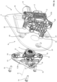
- the Fig. 2a provides a view into the cable drive housing as the first housing part 5a as well as a drying room T facing or located in this first plate side of the support plate 2 and on the back of the second housing part 5b of the cable drive 3.
- the Fig. 2b provides a view into or onto the gear housing as the second housing part 5b as well as onto a second plate side of the carrier plate 2 facing or located in a wet room N and onto the back of the first housing part 5a as the cable drive housing.
- the cable drum 4 can be seen, which (on the output side) sits on a bearing pin 12 of the cable drive housing as the first housing part 5a and is mounted there so as to be rotatable about the rotation axis D.
- the cable drum 4 is coupled (on the drive side) to a drive pin 13, which in turn is coupled to a gear 14 acting as a 90° deflection gear, preferably in the form of a worm gear.
- the gear 14, which is a component of the cable drive 3 is coupled to an electric motor 15, which is mounted on the gear housing as the second housing part 5b via a motor-gear interface 16.
- a plug connection 17 is used to supply current to the motor electronics or to control the electric motor 15 of the cable drive 3.
- the first housing part (cable drive housing) 5a which rotatably accommodates the cable drum 4, has a number of through-openings 18, positioned in a triangular arrangement in the exemplary embodiment, each for a screw element 19.
- the through-openings 18 correspond or are aligned with screw bosses 20 of the second housing part (gearbox housing) 5b, into which screw bosses 20 the screw elements 19 can be screwed.
- the first housing part (cable drive housing) 5a and the second housing part (motor drive or gearbox housing) 5b form the housing assembly 5, which can be screwed together using the screw elements 19.
- Both housing parts 5a, 5b, but in particular the second housing part 5b on the motor side, are made of plastic.
- the first housing part 5a has plug-in pins 21 through which the through-holes 18 of the screw elements pass.
- the screw bosses 20 of the second housing part 5b have plug-in pockets 22, drawn in the longitudinal direction of the screw(s), for receiving the corresponding plug-in pins 21 of the first housing part 5a.
- the support plate 2 has through-holes 23 for passing through or inserting the screw elements 19, which are aligned with the through-holes 18 or with the hollow plug pins 21 of the first housing part 5a receiving the cable drum 4, and with the screw bosses 20 or with the plug-in pockets 22 of the motor-side second housing part 5b.
- Fig. 3 shows the screw element 19 with a self-tapping thread 24. With this thread shape, the screw element 19 automatically cuts into the respective screw dome 20 of the second, motor- or drive-side housing part 5b.
- the first housing part (cable drive housing) 5a and the second, motor-side housing part 5b are pulled against each other—with the support plate 2 interposed—and screwed together to form the housing assembly 5.
- the screw element 19 has a screw head 19a with a first tool holder 25, also referred to below as the primary drive, and a threaded shaft 19b as well as a shaft tip 19c at the shaft end (facing away from the screw head).
- a second tool holder 26 is incorporated into the screw element 19 as a secondary drive at or in the shaft tip 19c or at the end face of the shaft end facing away from the screw head 19a.
- This second tool holder 26 at or in the shaft tip 19c of the screw element 19 is designed, for example, as a hexagon socket or a hexalobular socket (Torx), in particular with a diameter (inner diameter) of 3.5 mm or 4 mm.
- the screw element 19 can be actuated from the dry room side T by means of a corresponding, compatible tool, so that the screw connection (screwing) of the two housing parts 5a and 5b of the housing assembly 5 of the cable drive 3 can always be loosened on or from the dry room side T.
- the threaded shaft 19b of the screw element 19 or the shaft of the screw element 19 has a first shaft section 27a adjoining the screw head 19a with a first outer diameter (core or shaft diameter) d 1 and a second shaft section 27b opening into the shaft tip 19c with a second outer diameter (core or screw diameter) d 2.
- the (outer) diameter d 1 of the first shaft section 27a is smaller than or in comparison to the (outer) diameter d 2 of the second shaft section 27b, for example in that this first shaft section 27a is threadless and/or the diameter of the shaft core of this first shaft section 27a is smaller than that of the second shaft section 27b.
- Fig. 4a shows a partial schematic or sectional view of the screw connection in one of the screw domes 20 of the drive- or motor-side second housing part 5b with the joining connection of the corresponding plug pin 21 of the cable drum-side first housing part (cable drive housing) 5a with or in the plug pocket 22 of the corresponding screw dome 20.
- the screw element 19 here has, for example, a metric (external) thread 24.
- a screw sleeve with an internal thread corresponding to the (external) thread 24 of the screw element 19 is then arranged.
- the first shaft section 27a with the reduced or tapered outer diameter d 1 of the screw element 19 is located in the area of the through-opening 18 or in the plug-in pin 21 of the first, cable drum-side housing part 5a. Due to the fact that the clear width or the inner diameter of the through-opening 18 and/or the plug-in pin 21 is larger than the (outer) diameter of this first shaft section 27a of the screw element 19, no screw connection takes place in the area of the through-opening 18 or the plug-in pin 21 of the first, cable drum-side housing part 5a, and the two housing parts 5a and 5b can be pulled or clamped against each other during the screw connection.
- Fig. 4b illustrates the released state of the screw element 19, in that it is actuated via the secondary drive, i.e. the tool holder at the tip 19c, and is unscrewed from the screw dome 20.
- the screw element 19 remains with the shaft tip 19c in the through-opening 18 or in the plug-in pin 21 of the cable drum-side first housing part (cable drive housing) 5a.
- the through-opening 18 or the plug-in pin 21 have inwardly directed ribs or webs, for example as form-locking elements, in order to hold the screw element 19 at or in this position in the through-opening 18 or in the plug pin 21 of the cable drum-side first housing part (cable drive housing) 5a, in particular in a form-fitting and/or clamping or captive manner.
- the latter can be reassembled by establishing the screw connection or screw connection of the two housing parts 5a and 5b on or from the dry-room side T.
- the (positively locking) connection between the plug pin 21 and the screw dome 20 can also be released as the screw element 19 slides out of the screw dome 20.
- the thread 24 can also extend over both shaft sections 27a, 27b, i.e., over the entire threaded or screw shaft 19b.
Landscapes
- Engineering & Computer Science (AREA)
- Mechanical Engineering (AREA)
- Power-Operated Mechanisms For Wings (AREA)
- Window Of Vehicle (AREA)
Claims (10)
- Ensemble de boîtier (5) pour un module de porte (1) d'une porte de véhicule d'un véhicule automobile, présentant- une première partie de boîtier (5a) prévue et adaptée pour recevoir un tambour de câble (4) d'un lève-vitre à câble, avec un nombre d'ouvertures de passage (18),- une deuxième partie de boîtier (5b) associée à un entraînement par câble (3), qui présente des dômes à vis (20) correspondant aux ouvertures de passage (18) de la première partie de boîtier (5b), et- un nombre d'éléments de vissage (19) avec une tige filetée (19b) correspondant au nombre de dômes à vis (20),caractérisé en ce que- l'élément de vissage respectif (19) présente un logement d'outil (25, 26) aux deux extrémités de la tige, notamment l'élément de vissage respectif (19) présente une tête de vis (19a) avec un premier logement d'outil (25) et une tige filetée (19b) avec une pointe de tige (19c) ainsi qu'un deuxième logement d'outil (26) sur ou dans la pointe de tige (19c), de telle sorte que l'élément de vissage respectif (19) est accessible pour son actionnement, notamment pour visser ou pour desserrer la liaison par vis, aux deux extrémités de la tige, notamment depuis le côté arrière aussi bien de la première partie de boîtier (5a) que de la deuxième partie de boîtier (5b).
- Ensemble de boîtier (5) selon la revendication 1, caractérisé en ce que- la première partie de boîtier (5a) présente des tenons d'enfichage (21) traversés par les ouvertures de passage (18) pour les éléments de vissage (20), et/ou- la première partie de boîtier (5a) présente un nombre d'ouvertures de passage (18) et/ou de tenons d'enfichage (21), de préférence trois, agencés dans la zone des coins d'un triangle ou positionnés selon un agencement triangulaire.
- Ensemble de boîtier (5) selon la revendication 1 ou 2,
caractérisé en ce que- le dôme à vis (20) respectif de la deuxième partie de boîtier (5b) présente une poche d'enfichage (22) pour recevoir un tenon d'enfichage (21) correspondant de la première partie de boîtier (5a), et/ou- la deuxième partie de boîtier (5b) présente un nombre de dômes à vis (20), de préférence trois, agencés dans la zone des coins d'un triangle ou positionnés selon un agencement triangulaire. - Ensemble de boîtier (5) selon l'une quelconque des revendications 1 à 3,
caractérisé en ce que- le filetage (24) de l'élément de vissage respectif (19) est autotaraudeur ou métrique, et/ou- la tige filetée (19b) de l'élément de vissage respectif (19) présente une première section de tige (27a) se raccordant à la tête de vis (19a) avec un premier diamètre extérieur ou de tige (d1) et une deuxième section de tige (27b) débouchant dans la pointe de tige (19c) avec un deuxième diamètre extérieur ou de vis (d2). - Ensemble de boîtier (5) selon la revendication 4, caractérisé en ce que
le diamètre extérieur ou de tige (d1) de la première section de tige (27a) est plus petit que le diamètre extérieur ou de vis (d2) de la deuxième section de tige (27b). - Ensemble de boîtier (5) selon l'une quelconque des revendications 1 à 5,
caractérisé en ce que- le deuxième logement d'outil (26) est réalisé sur la pointe de tige (19c) de l'élément de vissage respectif (19) sous forme de polygone intérieur ou extérieur, et/ou- le deuxième logement d'outil (26) présente, à la pointe de tige (19c) de l'élément de vissage respectif (19), un diamètre intérieur de 3 mm à 5 mm, de préférence de (3,5 ± 0,5) mm. - Ensemble de boîtier (5) selon l'une quelconque des revendications 1 à 6,
caractérisé en ce que
lors du desserrage de l'élément de vissage respectif (19) par l'intermédiaire du deuxième logement d'outil (26) sur la pointe de tige (19c) de l'élément de vissage (19), une liaison, notamment une liaison par complémentarité de forme, du ou sur le vissage respectif est desserrée et l'élément de vissage (19) est maintenu sans risque de perte dans l'ouverture de passage associée (19) ou dans le tenon d'enfichage (21) de la première partie de boîtier (5a). - Module de porte (1) pour une porte de véhicule d'un véhicule automobile, présentant- une plaque de support (2) sur laquelle est monté ou peut être monté un entraînement par câble (3) d'un lève-vitre, l'entraînement par câble (3) étant couplé à un tambour de câble (4) pour un câble de traction (6) relié ou pouvant être relié à un entraîneur de vitre (9), et- un ensemble de boîtier (5) selon l'une quelconque des revendications 1 à 7,- la première partie de boîtier (5a) recevant le tambour de câble (4) étant agencée sur un premier côté de plaque (N) et la deuxième partie de boîtier (5b) étant agencée sur un deuxième côté de plaque (T) opposé de la plaque de support (2), et- l'élément de vissage respectif (19) sur le deuxième côté de plaque (T) pouvant être actionné, notamment pouvant être desserré, pour le démontage de la deuxième partie de boîtier (5b) vissée à la première partie de boîtier (5a).
- Module de porte (1) selon la revendication 8, caractérisé en ce que
la plaque de support (2) présente des ouvertures de passage (23) pour les éléments de vissage (19), qui sont alignées avec les ouvertures de passage (18) de la première partie de boîtier (5a) et avec les dômes à vis (20) de la deuxième partie de boîtier (5b). - Module de porte (1) selon la revendication 8 ou 9, caractérisé en ce que
la première partie de boîtier (5a) recevant le tambour de câble (4) est agencée sur un côté d'espace humide (N) et la deuxième partie de boîtier (5b) sur un côté d'espace sec (T) de la plaque de support (2).
Applications Claiming Priority (2)
| Application Number | Priority Date | Filing Date | Title |
|---|---|---|---|
| DE102021213597.8A DE102021213597A1 (de) | 2021-12-01 | 2021-12-01 | Türmodul und Gehäusebaugruppe eines Fahrzeugfensterhebers |
| PCT/EP2022/083806 WO2023099542A1 (fr) | 2021-12-01 | 2022-11-30 | Module de portière et ensemble boîtier d'un lève-vitre de véhicule |
Publications (2)
| Publication Number | Publication Date |
|---|---|
| EP4423356A1 EP4423356A1 (fr) | 2024-09-04 |
| EP4423356B1 true EP4423356B1 (fr) | 2025-07-02 |
Family
ID=84536166
Family Applications (1)
| Application Number | Title | Priority Date | Filing Date |
|---|---|---|---|
| EP22823451.4A Active EP4423356B1 (fr) | 2021-12-01 | 2022-11-30 | Module de portière et ensemble boîtier d'un lève-vitre de véhicule |
Country Status (5)
| Country | Link |
|---|---|
| US (1) | US20250033442A1 (fr) |
| EP (1) | EP4423356B1 (fr) |
| CN (1) | CN118401736A (fr) |
| DE (1) | DE102021213597A1 (fr) |
| WO (1) | WO2023099542A1 (fr) |
Family Cites Families (5)
| Publication number | Priority date | Publication date | Assignee | Title |
|---|---|---|---|---|
| DE3541379A1 (de) | 1985-11-22 | 1987-05-27 | Brose Fahrzeugteile | Einstellbarer bewegungsanschlag fuer einen hebearm eines fensterhebers |
| FR2829092B1 (fr) | 2001-09-04 | 2007-01-05 | Meritor Light Vehicle Sys Ltd | Portiere de cabriolet a rail reglable et procede d'assemblage correspondant |
| DE102010052095A1 (de) * | 2010-11-20 | 2011-07-07 | Daimler AG, 70327 | Befestigungsanordnung und Schraube |
| DE102016212041B4 (de) | 2016-07-01 | 2019-07-04 | Brose Fahrzeugteile Gmbh & Co. Kommanditgesellschaft, Bamberg | Gehäusebaugruppe für einen Fahrzeugfensterheber |
| US11002060B2 (en) | 2018-09-17 | 2021-05-11 | Hi-Lex Controls, Inc. | Drive unit assembly for a window regulator |
-
2021
- 2021-12-01 DE DE102021213597.8A patent/DE102021213597A1/de active Pending
-
2022
- 2022-11-30 EP EP22823451.4A patent/EP4423356B1/fr active Active
- 2022-11-30 US US18/715,839 patent/US20250033442A1/en active Pending
- 2022-11-30 WO PCT/EP2022/083806 patent/WO2023099542A1/fr not_active Ceased
- 2022-11-30 CN CN202280079850.8A patent/CN118401736A/zh active Pending
Also Published As
| Publication number | Publication date |
|---|---|
| CN118401736A (zh) | 2024-07-26 |
| DE102021213597A1 (de) | 2023-06-01 |
| US20250033442A1 (en) | 2025-01-30 |
| WO2023099542A1 (fr) | 2023-06-08 |
| EP4423356A1 (fr) | 2024-09-04 |
Similar Documents
| Publication | Publication Date | Title |
|---|---|---|
| EP0892724B1 (fr) | Dispositif de fixation | |
| EP2217469B1 (fr) | Élément de positionnement | |
| EP3743579B1 (fr) | Entraîneur pour un lèvre-vitre de véhicule, et lèvre-vitre de véhicule | |
| DE60123691T2 (de) | Zusammenbau einer Türplatte | |
| DE102012013979A1 (de) | Linaearaktuator und Verfahren zum Herstellen eines Linearaktuators | |
| EP0796753A2 (fr) | Dispositif et méthode pour ajuster une fenêtre sans cadre, entraînée par un lève-vitre à câble à deux boucles, par un basculement perpendiculaire à l'axe longitudinale du véhicule | |
| EP4015848A1 (fr) | Dispositif d'entraînement par câble d'un véhicule automobile | |
| DE19755899A1 (de) | Antriebseinheit für Verstelleinrichtungen | |
| DE3348215C2 (fr) | ||
| DE69900610T2 (de) | Scharnier für KFZ-Türe, insbesondere für eine Heckklappe | |
| DE102019215368A1 (de) | Verbindungselement einer Seilrollenbaugruppe eines Fensterhebers | |
| EP1192060B1 (fr) | Dispositif de fixation pour la partie d'une ferrure fixee sur la partie de siege ou sur la partie de cadre | |
| DE69408612T2 (de) | Antriebs- und Arretiervorrichtung für Kraftfahrzeugfenster | |
| EP4423356B1 (fr) | Module de portière et ensemble boîtier d'un lève-vitre de véhicule | |
| EP4411151B1 (fr) | Élément de réglage doté d'un manchon de fixation amortissant et son procédé d'installation et de fabrication | |
| DE102011007298B4 (de) | Motor-Getriebekombination eines Rollosystems | |
| EP1612432B1 (fr) | Dispositif de fixation pour habillage et méthode de fixation | |
| EP0384219B1 (fr) | Dispositif d'entraînement pour une lève-glace à câble Bowden | |
| DE3539576A1 (de) | Tuerscharnier fuer eine kraftfahrzeugtuer | |
| EP1885979A1 (fr) | Gond a charniere et charniere | |
| DE102008005744B3 (de) | Befestigungseinrichtung für Fensterhebermodule | |
| DE202011100077U1 (de) | Antriebsbaugruppe mit unterschiedlichen Befestigungen und Verbindungselement zur Befestigung | |
| DE102024202282A1 (de) | Türbaugruppe und Türmodul einer Fahrzeugtür | |
| DE102005050750A1 (de) | Befestigungsvorrichtung für Antriebseinheit mit Kunststoffgehäuse | |
| WO2024188757A1 (fr) | Ensemble lève-vitre pour véhicule automobile |
Legal Events
| Date | Code | Title | Description |
|---|---|---|---|
| STAA | Information on the status of an ep patent application or granted ep patent |
Free format text: STATUS: UNKNOWN |
|
| STAA | Information on the status of an ep patent application or granted ep patent |
Free format text: STATUS: THE INTERNATIONAL PUBLICATION HAS BEEN MADE |
|
| PUAI | Public reference made under article 153(3) epc to a published international application that has entered the european phase |
Free format text: ORIGINAL CODE: 0009012 |
|
| STAA | Information on the status of an ep patent application or granted ep patent |
Free format text: STATUS: REQUEST FOR EXAMINATION WAS MADE |
|
| 17P | Request for examination filed |
Effective date: 20240529 |
|
| AK | Designated contracting states |
Kind code of ref document: A1 Designated state(s): AL AT BE BG CH CY CZ DE DK EE ES FI FR GB GR HR HU IE IS IT LI LT LU LV MC ME MK MT NL NO PL PT RO RS SE SI SK SM TR |
|
| GRAP | Despatch of communication of intention to grant a patent |
Free format text: ORIGINAL CODE: EPIDOSNIGR1 |
|
| STAA | Information on the status of an ep patent application or granted ep patent |
Free format text: STATUS: GRANT OF PATENT IS INTENDED |
|
| DAV | Request for validation of the european patent (deleted) | ||
| DAX | Request for extension of the european patent (deleted) | ||
| INTG | Intention to grant announced |
Effective date: 20250224 |
|
| GRAS | Grant fee paid |
Free format text: ORIGINAL CODE: EPIDOSNIGR3 |
|
| GRAA | (expected) grant |
Free format text: ORIGINAL CODE: 0009210 |
|
| STAA | Information on the status of an ep patent application or granted ep patent |
Free format text: STATUS: THE PATENT HAS BEEN GRANTED |
|
| AK | Designated contracting states |
Kind code of ref document: B1 Designated state(s): AL AT BE BG CH CY CZ DE DK EE ES FI FR GB GR HR HU IE IS IT LI LT LU LV MC ME MK MT NL NO PL PT RO RS SE SI SK SM TR |
|
| REG | Reference to a national code |
Ref country code: GB Ref legal event code: FG4D Free format text: NOT ENGLISH |
|
| REG | Reference to a national code |
Ref country code: CH Ref legal event code: EP |
|
| REG | Reference to a national code |
Ref country code: DE Ref legal event code: R096 Ref document number: 502022004553 Country of ref document: DE |
|
| REG | Reference to a national code |
Ref country code: IE Ref legal event code: FG4D Free format text: LANGUAGE OF EP DOCUMENT: GERMAN |
|
| REG | Reference to a national code |
Ref country code: NL Ref legal event code: MP Effective date: 20250702 |
|
| PG25 | Lapsed in a contracting state [announced via postgrant information from national office to epo] |
Ref country code: PT Free format text: LAPSE BECAUSE OF FAILURE TO SUBMIT A TRANSLATION OF THE DESCRIPTION OR TO PAY THE FEE WITHIN THE PRESCRIBED TIME-LIMIT Effective date: 20251103 |
|
| PG25 | Lapsed in a contracting state [announced via postgrant information from national office to epo] |
Ref country code: NL Free format text: LAPSE BECAUSE OF FAILURE TO SUBMIT A TRANSLATION OF THE DESCRIPTION OR TO PAY THE FEE WITHIN THE PRESCRIBED TIME-LIMIT Effective date: 20250702 |
|
| PG25 | Lapsed in a contracting state [announced via postgrant information from national office to epo] |
Ref country code: IS Free format text: LAPSE BECAUSE OF FAILURE TO SUBMIT A TRANSLATION OF THE DESCRIPTION OR TO PAY THE FEE WITHIN THE PRESCRIBED TIME-LIMIT Effective date: 20251102 |
|
| PGFP | Annual fee paid to national office [announced via postgrant information from national office to epo] |
Ref country code: DE Payment date: 20251130 Year of fee payment: 4 |
|
| PG25 | Lapsed in a contracting state [announced via postgrant information from national office to epo] |
Ref country code: NO Free format text: LAPSE BECAUSE OF FAILURE TO SUBMIT A TRANSLATION OF THE DESCRIPTION OR TO PAY THE FEE WITHIN THE PRESCRIBED TIME-LIMIT Effective date: 20251002 |
|
| REG | Reference to a national code |
Ref country code: LT Ref legal event code: MG9D |
|
| PG25 | Lapsed in a contracting state [announced via postgrant information from national office to epo] |
Ref country code: FI Free format text: LAPSE BECAUSE OF FAILURE TO SUBMIT A TRANSLATION OF THE DESCRIPTION OR TO PAY THE FEE WITHIN THE PRESCRIBED TIME-LIMIT Effective date: 20250702 |
|
| PG25 | Lapsed in a contracting state [announced via postgrant information from national office to epo] |
Ref country code: HR Free format text: LAPSE BECAUSE OF FAILURE TO SUBMIT A TRANSLATION OF THE DESCRIPTION OR TO PAY THE FEE WITHIN THE PRESCRIBED TIME-LIMIT Effective date: 20250702 |
|
| PG25 | Lapsed in a contracting state [announced via postgrant information from national office to epo] |
Ref country code: GR Free format text: LAPSE BECAUSE OF FAILURE TO SUBMIT A TRANSLATION OF THE DESCRIPTION OR TO PAY THE FEE WITHIN THE PRESCRIBED TIME-LIMIT Effective date: 20251003 |
|
| PG25 | Lapsed in a contracting state [announced via postgrant information from national office to epo] |
Ref country code: CZ Free format text: LAPSE BECAUSE OF FAILURE TO SUBMIT A TRANSLATION OF THE DESCRIPTION OR TO PAY THE FEE WITHIN THE PRESCRIBED TIME-LIMIT Effective date: 20250702 Ref country code: SE Free format text: LAPSE BECAUSE OF FAILURE TO SUBMIT A TRANSLATION OF THE DESCRIPTION OR TO PAY THE FEE WITHIN THE PRESCRIBED TIME-LIMIT Effective date: 20250702 |
|
| PG25 | Lapsed in a contracting state [announced via postgrant information from national office to epo] |
Ref country code: LV Free format text: LAPSE BECAUSE OF FAILURE TO SUBMIT A TRANSLATION OF THE DESCRIPTION OR TO PAY THE FEE WITHIN THE PRESCRIBED TIME-LIMIT Effective date: 20250702 |
|
| PG25 | Lapsed in a contracting state [announced via postgrant information from national office to epo] |
Ref country code: PL Free format text: LAPSE BECAUSE OF FAILURE TO SUBMIT A TRANSLATION OF THE DESCRIPTION OR TO PAY THE FEE WITHIN THE PRESCRIBED TIME-LIMIT Effective date: 20250702 Ref country code: BG Free format text: LAPSE BECAUSE OF FAILURE TO SUBMIT A TRANSLATION OF THE DESCRIPTION OR TO PAY THE FEE WITHIN THE PRESCRIBED TIME-LIMIT Effective date: 20250702 |
|
| PG25 | Lapsed in a contracting state [announced via postgrant information from national office to epo] |
Ref country code: RS Free format text: LAPSE BECAUSE OF FAILURE TO SUBMIT A TRANSLATION OF THE DESCRIPTION OR TO PAY THE FEE WITHIN THE PRESCRIBED TIME-LIMIT Effective date: 20251002 |
|
| PG25 | Lapsed in a contracting state [announced via postgrant information from national office to epo] |
Ref country code: ES Free format text: LAPSE BECAUSE OF FAILURE TO SUBMIT A TRANSLATION OF THE DESCRIPTION OR TO PAY THE FEE WITHIN THE PRESCRIBED TIME-LIMIT Effective date: 20250702 |
|
| PG25 | Lapsed in a contracting state [announced via postgrant information from national office to epo] |
Ref country code: RO Free format text: LAPSE BECAUSE OF FAILURE TO SUBMIT A TRANSLATION OF THE DESCRIPTION OR TO PAY THE FEE WITHIN THE PRESCRIBED TIME-LIMIT Effective date: 20250702 |
|
| PG25 | Lapsed in a contracting state [announced via postgrant information from national office to epo] |
Ref country code: SM Free format text: LAPSE BECAUSE OF FAILURE TO SUBMIT A TRANSLATION OF THE DESCRIPTION OR TO PAY THE FEE WITHIN THE PRESCRIBED TIME-LIMIT Effective date: 20250702 |
|
| PG25 | Lapsed in a contracting state [announced via postgrant information from national office to epo] |
Ref country code: DK Free format text: LAPSE BECAUSE OF FAILURE TO SUBMIT A TRANSLATION OF THE DESCRIPTION OR TO PAY THE FEE WITHIN THE PRESCRIBED TIME-LIMIT Effective date: 20250702 |
|
| PG25 | Lapsed in a contracting state [announced via postgrant information from national office to epo] |
Ref country code: IT Free format text: LAPSE BECAUSE OF FAILURE TO SUBMIT A TRANSLATION OF THE DESCRIPTION OR TO PAY THE FEE WITHIN THE PRESCRIBED TIME-LIMIT Effective date: 20250702 |
|
| PG25 | Lapsed in a contracting state [announced via postgrant information from national office to epo] |
Ref country code: SK Free format text: LAPSE BECAUSE OF FAILURE TO SUBMIT A TRANSLATION OF THE DESCRIPTION OR TO PAY THE FEE WITHIN THE PRESCRIBED TIME-LIMIT Effective date: 20250702 Ref country code: EE Free format text: LAPSE BECAUSE OF FAILURE TO SUBMIT A TRANSLATION OF THE DESCRIPTION OR TO PAY THE FEE WITHIN THE PRESCRIBED TIME-LIMIT Effective date: 20250702 |