EP4423368B1 - Turbinengeneratoranordnung - Google Patents
Turbinengeneratoranordnung Download PDFInfo
- Publication number
- EP4423368B1 EP4423368B1 EP23790699.5A EP23790699A EP4423368B1 EP 4423368 B1 EP4423368 B1 EP 4423368B1 EP 23790699 A EP23790699 A EP 23790699A EP 4423368 B1 EP4423368 B1 EP 4423368B1
- Authority
- EP
- European Patent Office
- Prior art keywords
- central element
- turbine
- compressor
- generator assembly
- turbine generator
- Prior art date
- Legal status (The legal status is an assumption and is not a legal conclusion. Google has not performed a legal analysis and makes no representation as to the accuracy of the status listed.)
- Active
Links
Images



Classifications
-
- F—MECHANICAL ENGINEERING; LIGHTING; HEATING; WEAPONS; BLASTING
- F01—MACHINES OR ENGINES IN GENERAL; ENGINE PLANTS IN GENERAL; STEAM ENGINES
- F01D—NON-POSITIVE DISPLACEMENT MACHINES OR ENGINES, e.g. STEAM TURBINES
- F01D15/00—Adaptations of machines or engines for special use; Combinations of engines with devices driven thereby
- F01D15/10—Adaptations for driving, or combinations with, electric generators
-
- F—MECHANICAL ENGINEERING; LIGHTING; HEATING; WEAPONS; BLASTING
- F01—MACHINES OR ENGINES IN GENERAL; ENGINE PLANTS IN GENERAL; STEAM ENGINES
- F01D—NON-POSITIVE DISPLACEMENT MACHINES OR ENGINES, e.g. STEAM TURBINES
- F01D15/00—Adaptations of machines or engines for special use; Combinations of engines with devices driven thereby
- F01D15/08—Adaptations for driving, or combinations with, pumps
-
- F—MECHANICAL ENGINEERING; LIGHTING; HEATING; WEAPONS; BLASTING
- F01—MACHINES OR ENGINES IN GENERAL; ENGINE PLANTS IN GENERAL; STEAM ENGINES
- F01D—NON-POSITIVE DISPLACEMENT MACHINES OR ENGINES, e.g. STEAM TURBINES
- F01D21/00—Shutting-down of machines or engines, e.g. in emergency; Regulating, controlling, or safety means not otherwise provided for
- F01D21/003—Arrangements for testing or measuring
-
- F—MECHANICAL ENGINEERING; LIGHTING; HEATING; WEAPONS; BLASTING
- F01—MACHINES OR ENGINES IN GENERAL; ENGINE PLANTS IN GENERAL; STEAM ENGINES
- F01D—NON-POSITIVE DISPLACEMENT MACHINES OR ENGINES, e.g. STEAM TURBINES
- F01D25/00—Component parts, details, or accessories, not provided for in, or of interest apart from, other groups
- F01D25/16—Arrangement of bearings; Supporting or mounting bearings in casings
-
- F—MECHANICAL ENGINEERING; LIGHTING; HEATING; WEAPONS; BLASTING
- F02—COMBUSTION ENGINES; HOT-GAS OR COMBUSTION-PRODUCT ENGINE PLANTS
- F02C—GAS-TURBINE PLANTS; AIR INTAKES FOR JET-PROPULSION PLANTS; CONTROLLING FUEL SUPPLY IN AIR-BREATHING JET-PROPULSION PLANTS
- F02C7/00—Features, components parts, details or accessories, not provided for in, or of interest apart form groups F02C1/00 - F02C6/00; Air intakes for jet-propulsion plants
- F02C7/06—Arrangements of bearings; Lubricating
-
- H—ELECTRICITY
- H02—GENERATION; CONVERSION OR DISTRIBUTION OF ELECTRIC POWER
- H02K—DYNAMO-ELECTRIC MACHINES
- H02K11/00—Structural association of dynamo-electric machines with electric components or with devices for shielding, monitoring or protection
- H02K11/20—Structural association of dynamo-electric machines with electric components or with devices for shielding, monitoring or protection for measuring, monitoring, testing, protecting or switching
- H02K11/21—Devices for sensing speed or position, or actuated thereby
- H02K11/225—Detecting coils
-
- H—ELECTRICITY
- H02—GENERATION; CONVERSION OR DISTRIBUTION OF ELECTRIC POWER
- H02K—DYNAMO-ELECTRIC MACHINES
- H02K7/00—Arrangements for handling mechanical energy structurally associated with dynamo-electric machines, e.g. structural association with mechanical driving motors or auxiliary dynamo-electric machines
- H02K7/08—Structural association with bearings
-
- H—ELECTRICITY
- H02—GENERATION; CONVERSION OR DISTRIBUTION OF ELECTRIC POWER
- H02K—DYNAMO-ELECTRIC MACHINES
- H02K7/00—Arrangements for handling mechanical energy structurally associated with dynamo-electric machines, e.g. structural association with mechanical driving motors or auxiliary dynamo-electric machines
- H02K7/18—Structural association of electric generators with mechanical driving motors, e.g. with turbines
- H02K7/1807—Rotary generators
- H02K7/1823—Rotary generators structurally associated with turbines or similar engines
-
- F—MECHANICAL ENGINEERING; LIGHTING; HEATING; WEAPONS; BLASTING
- F05—INDEXING SCHEMES RELATING TO ENGINES OR PUMPS IN VARIOUS SUBCLASSES OF CLASSES F01-F04
- F05D—INDEXING SCHEME FOR ASPECTS RELATING TO NON-POSITIVE-DISPLACEMENT MACHINES OR ENGINES, GAS-TURBINES OR JET-PROPULSION PLANTS
- F05D2220/00—Application
- F05D2220/70—Application in combination with
- F05D2220/76—Application in combination with an electrical generator
-
- F—MECHANICAL ENGINEERING; LIGHTING; HEATING; WEAPONS; BLASTING
- F05—INDEXING SCHEMES RELATING TO ENGINES OR PUMPS IN VARIOUS SUBCLASSES OF CLASSES F01-F04
- F05D—INDEXING SCHEME FOR ASPECTS RELATING TO NON-POSITIVE-DISPLACEMENT MACHINES OR ENGINES, GAS-TURBINES OR JET-PROPULSION PLANTS
- F05D2240/00—Components
- F05D2240/50—Bearings
- F05D2240/54—Radial bearings
Definitions
- the present invention relates to an assembly which forms part of a turbogenerator and is intended for use in an electricity generation or energy cogeneration apparatus.
- Known electricity production or energy cogeneration devices comprise a combustion device supplying combustion gas to a turbine mechanically coupled to a compressor compressing air injected into the combustion device.
- a combustion device supplying combustion gas to a turbine mechanically coupled to a compressor compressing air injected into the combustion device.
- Such a device is for example described in the document WO2022089822A1 .
- the first radial bearing is the only radial bearing between the turbine and the compressor.
- the radial bearings are located axially on either side of the compressor: the first bearing is located between the turbine and the compressor, and the second bearing is located between the compressor and the motor-generator.
- the first radial bearing is the only radial bearing between the turbine and the compressor, there is no other radial bearing between the turbine and the compressor than the first radial bearing. This reduces the distance between the turbine and the compressor, thus improving the stability of the system.
- the position of the second bearing, on the other side of the compressor relative to the turbine makes it possible to reduce the distance between the turbine and the compressor, to better ventilate the region between the turbine and the compressor which is very hot, and therefore to improve the stability of the system.
- the system is designed to rotate preferably at a speed of at least 80,000 revolutions per minute, more preferably at least 100,000 revolutions per minute. It may, for example, be designed to rotate at a speed between 90,000 and 150,000 revolutions per minute.
- the "motor-generator” operates as a motor when supplied with electrical energy and provides energy in the form of motion, and as a generator when supplied with energy in the form of motion and provides electrical energy.
- the term “motor-generator” may be substituted in this document by "motor and/or generator”.
- the motor-generator is an electric motor-generator comprising a rotor and a stator.
- the rotor of the motor-generator is formed of a portion of the central element on which a rotor magnetic device is fixed.
- the rotor magnetic device comprises one or more magnets, preferably permanent.
- a "radial” bearing is a bearing preventing movement perpendicular to the axis of rotation
- an “axial” bearing is a bearing preventing movement parallel to the axis of rotation.
- Radial bearings may be separated, radially, from the central member by another rotating member and attached to the central member.
- a radial bearing is an aerodynamic bearing.
- the central element is levitated, separated from the bearing by a layer of air that supports the bearing by a lift effect. It is not a rolling bearing. It does not require lubrication.
- the turbogenerator assembly comprises an air duct opening onto the compressor, the air duct being located between the compressor and the second radial bearing and having a radial component.
- the air duct is between the second radial bearing and the compressor and is not parallel to the axis (i.e. it has a radial component). This allows the distance between the rotor and the stator to be particularly small, which improves the electro-magneto-mechanical stability of the system and reduces the reactive power, while improving the angular phase shift (cosine ⁇ ).
- the air duct may include one or more turns, include a radial section and/or include an inlet volute that takes the air from the side, and makes it spiral with a specific angle.
- the first radial bearing and the second radial bearing are foil bearings.
- Foil bearings allow the use of a larger diameter center element than would be possible with other bearings, such as ball bearings. This increases the first natural bending frequency, improving stability and high-speed operation.
- the central element is made of a single piece or a plurality of pieces fixed together so as to rotate integrally.
- the central element which extends from the turbine to the motor-generator via the compressor, therefore has a rotational speed that is identical over its entire length.
- a central element of one piece or made of integrally fixed parts simplifies the balancing procedure, which is particularly delicate in a turbine generator assembly such as that of the invention.
- the first radial bearing and the second radial bearing are the only radial bearings.
- the turbine generator assembly includes a thrust bearing and an axial bearing configured to prevent axial movement of the thrust bearing.
- the thrust bearing which may be called an axial thrust bearing, is preferably located between the turbine and the compressor. It is attached, directly or indirectly, to the central element.
- the turbine generator assembly comprises a shaft attached to the central element in a detachable manner and such that the shaft and the central element rotate together, the stop being part of the shaft.
- the shaft could also be called a "rotating element". The presence of the shaft, forming a separate part from the central element, allows the radial bearings, the compressor and the turbine to be slipped onto the central element.
- the motor-generator comprises a rotor fixed to the central element and comprising a bipole rotor magnetic device, preferably with permanent magnet(s).
- the rotor magnetic device has only one south pole and one north pole. Given the very high rotation speed, the system is therefore easier to straighten than with a quadrupole or with even more magnetic poles. This can be a single permanent magnet.
- the motor-generator comprises a rotor attached to the central element and comprising a rotor magnetic device located inside the central element.
- the rotor magnetic device which is particularly heavy, to be close to the axis. It is however possible, while remaining within the scope of the invention, for the rotor magnetic device to be fixed outside the central element, for example shrunk onto the central element.
- the central element comprises a cavity having an opening in a radial plane and located at one end of the central element, the rotor magnetic device being located in the cavity.
- the opening allows the rotor magnetic device to be inserted into the central element, centering it particularly precisely.
- the angular position sensor also allows the rotational speed of the central element to be determined.
- the inductive sensor is preferably aligned with the axis, facing the target. It is preferably connected to an electronic device supported by a bullet-shaped housing.
- the target consists of an insulating surface and a metallic radial element.
- the metallic radial element is the reference point of the inductive sensor.
- the central element has a diameter greater than 15 mm and less than 40 mm.
- the diameter of the central element may vary depending on the position along the axis, but preferably it is nowhere less than 15 mm or greater than 40 mm. A small diameter reduces the value of the first bending natural frequency, which deteriorates stability and high-speed operation. A large diameter reduces the efficiency of the turbine generator assembly. The claimed range allows a compromise between these two constraints.
- the invention also provides an apparatus for producing electricity or cogenerating energy comprising a turbogenerator assembly according to the invention.
- the only radial bearings are the first radial bearing and the second radial bearing.
- FIG. 1 schematically illustrates different elements of an electricity production or energy cogeneration device 2.
- the device 2 comprises a combustion device 90, a turbine 30, a compressor 20 and a motor-generator 70.
- the combustion device 90 transmits combustion gases, (i.e. resulting from combustion) to the turbine 30 via a first conduit 91.
- the turbine 30, the compressor 20 and the motor-generator 70 are mechanically coupled via a central element 10.
- the air compressed by the compressor 20 is sent to the combustion device 90 via a second conduit 92 and a recuperator 93 which preheats the compressed air before injection into the combustion device 90.
- the compressor 20 is preferably shrunk onto the central element 10.
- a turbogenerator assembly 1 comprises the turbine 30, the compressor 20, the motor-generator 70 and the central element 10 which are aligned to rotate about the axis 5. It is connected to the combustion device 90.
- the turbine 30, the compressor 20, the motor-generator 70 are arranged, axially, in the following order: turbine 30, compressor 20, motor-generator 70, so as to be axially distant from each other.
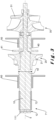
- FIG. 2 illustrates certain parts of an assembly for a turbogenerator 1. It notably shows the blades 31 of the turbine 30, the blades 21 of the compressor 20, and a rotor magnetic device 72 of the rotor 71 of the motor-generator 70.
- the turbine 30 and the compressor 20 are separated, axially, by a first radial bearing 50, which radially surrounds the central element 10.
- the first radial bearing 50 is, preferably, the only radial bearing between the turbine 30 and the compressor 20.
- the compressor 20 and the motor-generator 70 are separated, axially, by a second radial bearing 60, which radially surrounds the central element 10.
- the second radial bearing 60 axially separates the compressor from the rotor magnetic device 72.
- the second radial bearing 60 is, preferably, the only radial bearing between the compressor 20 and the motor-generator 70.
- the first radial bearing 50 and the second radial bearing 60 are preferably foil bearings.
- the first radial bearing 50 and the second radial bearing 60 are preferably the only radial bearings of the turbine generator assembly 1 and of the electricity production or energy cogeneration apparatus 2.
- the central element 10 is made of a single piece or a plurality of pieces fixed together so as to all rotate at the same angular speed, as if they were of one piece.
- the radial diameter 15 of the central element is greater than 15 mm and/or is less than 40 mm.
- the rotor magnetic device 72 is preferably a bipole, for example a magnet. In the embodiment of the Figure 2 , it is located in a cavity 11 inside the central element 10.
- the cavity 11 preferably comprises an opening opening axially onto the end 12 of the central element 10.
- the rotor magnetic device 72 is fixed to the outside of the central element 10, so as to surround it radially.
- the turbogenerator assembly 1 comprises an air duct 25 supplying air to the compressor 20.
- the air duct 25 is preferably located between the compressor 20 and the second radial bearing 60. It has a radial component, that is to say that the path of the air in this air duct 25 is not only axial.
- the turbogenerator assembly 1 preferably comprises a first bearing support 51 around the first radial bearing 50 and a second bearing support 61 around the second radial bearing 60.
- the first 51 and the second 61 bearing supports are fixed relative to each other and are concentric.
- the first 51 and the second 61 bearing supports are fixed relative to a stator 73 of the motor-generator 70.
- the turbogenerator assembly 1 preferably comprises a detector 110 for determining the angular position of the central element 10 and preferably the angular velocity of the central element 10.
- the detector 110 comprises a target 111 fixed to the end 12 of the central element 10 in a radial plane. It rotates with the central element 10 while remaining in the same plane.
- the detector 110 also comprises an inductive sensor 115 axially aligned with the target 111, and fixed relative to the stator 73 of the motor-generator 70. It is connected to an electronic device comprising an angular speed and/or position acquisition card which is supported by a box 116 in the shape of an ogive. Based on the measurement of angular position and/or angular speed, the electronic device makes it possible to carry out control and/or monitoring of the turbogenerator assembly 1 during its operation, which makes it possible to prevent it from stalling.
- FIG. 5 illustrates the target 111 in one embodiment of the invention. It consists of an insulating surface 112 and a metallic radial element 113. It is preferably pierced with an axial hole 114.
- the invention relates to a turbogenerator assembly 1 for an electricity production or energy cogeneration apparatus.
- the turbogenerator assembly 1 comprises, axially aligned and in this order: a turbine 30, a first radial bearing 50, a compressor 20, a second radial bearing 60, and a motor-generator 70.
Landscapes
- Engineering & Computer Science (AREA)
- Mechanical Engineering (AREA)
- General Engineering & Computer Science (AREA)
- Power Engineering (AREA)
- Chemical & Material Sciences (AREA)
- Combustion & Propulsion (AREA)
- Microelectronics & Electronic Packaging (AREA)
- Connection Of Motors, Electrical Generators, Mechanical Devices, And The Like (AREA)
- Structures Of Non-Positive Displacement Pumps (AREA)
- Magnetic Bearings And Hydrostatic Bearings (AREA)
- Supercharger (AREA)
Claims (14)
- Turbogeneratoranordnung (1), umfassend:- eine Turbine (30), die konfiguriert ist, um von einer Verbrennungsvorrichtung (90) mit Verbrennungsgas versorgt zu werden;- einen Kompressor (20), der über ein mittleres Element (10) mechanisch mit der Turbine (30) verbunden ist;- einen Motor-Generator (70), der axial von dem Kompressor (20) versetzt ist und mechanisch über das mittlere Element (10) mit der Turbine (30) und dem Kompressor (20) verbunden ist;- ein erstes radiales Lager (50), das axial zwischen der Turbine (30) und dem Kompressor (20) gelegen ist und dazu vorgesehen ist, das mittlere Element (10) drehend zu führen; und- ein zweites radiales Lager (60), das axial zwischen dem Kompressor (20) und dem Motor-Generator (70) gelegen ist und dazu vorgesehen ist, das mittlere Element (10) drehend zu führen;dadurch gekennzeichnet, dass das erste radiale Lager (50) das einzige radiale Lager zwischen der Turbine (30) und dem Kompressor (20) ist.
- Turbogeneratoranordnung nach Anspruch 1, umfassend einen Luftkanal (25), der zum Kompressor (20) führt, wobei der Luftkanal (25) zwischen dem Kompressor (20) und dem zweiten radialen Lager (60) gelegen ist und eine radiale Komponente aufweist.
- Turbogeneratoranordnung nach einem der vorstehenden Ansprüche, wobei das erste radiale Lager (50) und das zweite radiale Lager (60) Folienlager sind.
- Turbogeneratoranordnung nach einem der vorstehenden Ansprüche, wobei das mittlere Element (10) aus einem einzigen Werkstück oder einer Vielzahl von Werkstücken hergestellt ist, die so aneinander befestigt sind, dass sie sich integral drehen.
- Turbogeneratoranordnung nach einem der vorstehenden Ansprüche, wobei das erste radiale Lager (50) und das zweite radiale Lager (60) die einzigen radialen Lager sind.
- Turbogeneratoranordnung nach einem der vorstehenden Ansprüche, umfassend einen Anschlag (41) und ein axiales Lager (81), die konfiguriert sind, um eine axiale Bewegung des Anschlags (41) zu verhindern.
- Turbogeneratoranordnung nach Anspruch 6, umfassend eine Welle (40), die auf abnehmbare Weise am mittleren Element (10) befestigt ist und derart, dass die Welle (40) und das mittlere Element (10) sich gemeinsam drehen, wobei der Anschlag (41) Teil der Welle (40) ist.
- Turbogeneratoranordnung nach einem der vorstehenden Ansprüche, wobei der Motor-Generator (70) einen Rotor (71) umfasst, der am mittleren Element (10) befestigt ist und eine zweipolige Rotormagnetvorrichtung (72) umfasst.
- Turbogeneratoranordnung nach einem der vorstehenden Ansprüche, wobei der Motor-Generator (70) einen Rotor (71) umfasst, der am mittleren Element (10) befestigt ist, und eine zweipolige Rotormagnetvorrichtung (72) umfasst, das sich im Inneren des mittleren Elements (10) befindet.
- Turbogeneratoranordnung nach Anspruch 9, wobei das mittlere Element (10) einen Hohlraum (11) umfasst, der eine Öffnung in einer radialen Ebene aufweist und an einem Ende (12) des mittleren Elements (10) gelegen ist, wobei die Rotormagnetvorrichtung (72) im Hohlraum (11) gelegen ist.
- Turbogeneratoranordnung nach einem der vorstehenden Ansprüche, umfassend einen Winkelpositionsdetektor (110) des mittleren Elements (10), der Folgendes umfasst:- ein Ziel (111), das an einem Ende (12) des mittleren Elements (10) befestigt ist, und- einen induktiven Sensor (115), der in Bezug auf einen Stator (73) des Motor-Generators (70) fest ist.
- Turbogeneratoranordnung nach Anspruch 11, wobei das Ziel (111) aus einer isolierenden Oberfläche (112) und einem radialen Metallelement (113) besteht.
- Turbogeneratoranordnung nach einem der vorstehenden Ansprüche, wobei das mittlere Element (10) einen Durchmesser (15) größer als 15 mm und kleiner als 40 mm aufweist.
- Einrichtung zur Stromerzeugung oder zur Kraft-Wärme-Kopplung (2), umfassend eine Turbogeneratoranordnung (1) nach einem der vorstehenden Ansprüche.
Applications Claiming Priority (2)
| Application Number | Priority Date | Filing Date | Title |
|---|---|---|---|
| BE20225849A BE1030978B1 (fr) | 2022-10-21 | 2022-10-21 | Assemblage pour turbogénérateur |
| PCT/EP2023/079372 WO2024084087A1 (fr) | 2022-10-21 | 2023-10-20 | Assemblage pour turbogénérateur |
Publications (3)
| Publication Number | Publication Date |
|---|---|
| EP4423368A1 EP4423368A1 (de) | 2024-09-04 |
| EP4423368C0 EP4423368C0 (de) | 2025-04-02 |
| EP4423368B1 true EP4423368B1 (de) | 2025-04-02 |
Family
ID=83995628
Family Applications (2)
| Application Number | Title | Priority Date | Filing Date |
|---|---|---|---|
| EP23790700.1A Active EP4423369B1 (de) | 2022-10-21 | 2023-10-20 | Turbinengeneratoranordnung |
| EP23790699.5A Active EP4423368B1 (de) | 2022-10-21 | 2023-10-20 | Turbinengeneratoranordnung |
Family Applications Before (1)
| Application Number | Title | Priority Date | Filing Date |
|---|---|---|---|
| EP23790700.1A Active EP4423369B1 (de) | 2022-10-21 | 2023-10-20 | Turbinengeneratoranordnung |
Country Status (4)
| Country | Link |
|---|---|
| US (1) | US20260022645A1 (de) |
| EP (2) | EP4423369B1 (de) |
| BE (1) | BE1030978B1 (de) |
| WO (2) | WO2024084087A1 (de) |
Family Cites Families (8)
| Publication number | Priority date | Publication date | Assignee | Title |
|---|---|---|---|---|
| US6305169B1 (en) * | 1999-02-22 | 2001-10-23 | Ralph P. Mallof | Motor assisted turbocharger |
| FR2824135B1 (fr) * | 2001-04-25 | 2003-09-12 | Skf Ab | Dispositif optique de detection des parametres de rotation et palier a roulement equipe d'un tel dispositif |
| US6739845B2 (en) * | 2002-05-30 | 2004-05-25 | William E. Woollenweber | Compact turbocharger |
| FR2898676B1 (fr) * | 2006-03-14 | 2008-07-04 | Skf Ab | Dispositif de detection de position angulaire, moteur electrique, colonne de direction et reducteur |
| DE202006004975U1 (de) * | 2006-03-29 | 2006-07-20 | Grauli, Rolf | Elektromotorisch unterstützter Turbolader |
| DE102014210451A1 (de) * | 2014-06-03 | 2015-12-03 | Robert Bosch Gmbh | Turbolader mit elektrischer Maschine |
| FR3027103B1 (fr) * | 2014-10-08 | 2017-11-24 | Continental Automotive France | Ensemble de capteur de position angulaire pour moteur hybride de vehicule automobile a arbre commun |
| BE1028409B1 (fr) | 2020-10-30 | 2022-01-19 | Mitis SA | Chambre de combustion sans flamme et appareil de production d'électricité ou de cogénération d'énergie associé |
-
2022
- 2022-10-21 BE BE20225849A patent/BE1030978B1/fr active IP Right Grant
-
2023
- 2023-10-20 US US19/111,995 patent/US20260022645A1/en active Pending
- 2023-10-20 EP EP23790700.1A patent/EP4423369B1/de active Active
- 2023-10-20 WO PCT/EP2023/079372 patent/WO2024084087A1/fr not_active Ceased
- 2023-10-20 WO PCT/EP2023/079373 patent/WO2024084088A1/fr not_active Ceased
- 2023-10-20 EP EP23790699.5A patent/EP4423368B1/de active Active
Also Published As
| Publication number | Publication date |
|---|---|
| BE1030978A1 (fr) | 2024-05-22 |
| EP4423368C0 (de) | 2025-04-02 |
| EP4423369A1 (de) | 2024-09-04 |
| WO2024084087A1 (fr) | 2024-04-25 |
| EP4423369B1 (de) | 2025-04-02 |
| EP4423368A1 (de) | 2024-09-04 |
| US20260022645A1 (en) | 2026-01-22 |
| EP4423369C0 (de) | 2025-04-02 |
| WO2024084088A1 (fr) | 2024-04-25 |
| BE1030978B1 (fr) | 2024-05-27 |
Similar Documents
| Publication | Publication Date | Title |
|---|---|---|
| EP1382802B1 (de) | Integrierter Startgenerator für eine Turbomaschine | |
| EP1564397B1 (de) | Strahltriebwerks-Architektur mit zwei Fans an der Vorderseite | |
| CA2599039C (fr) | Dispositif d'entrainement du rotor d'un equipement auxiliaire d'un turbomoteur | |
| BE1022463B1 (fr) | Dynamometre pour banc d'essai de turbomachine d'aeronef | |
| FR2817088A1 (fr) | Machine tournante a butee axiale magnetique integrant une generatrice de courant | |
| WO2022128550A1 (fr) | Moteur electrique a flux axial | |
| EP4423368B1 (de) | Turbinengeneratoranordnung | |
| EP2618465B1 (de) | Elektrische Maschine, die zwei Rotoren und mindestens zwei Lager umfasst, mit einem Lager zwischen den beiden Rotoren entlang der Rotationsachse | |
| FR3064134A1 (fr) | Compresseur de suralimentation electrique avec support d'aimant | |
| EP1174986A1 (de) | Laminierter Rotor für Wirbelstrombremse und Vorrichtung mit einem solchen Rotor | |
| EP4348018B1 (de) | Turbomaschine mit magnetantriebspumpe | |
| FR3089363A1 (fr) | Compresseur electrique | |
| EP3139473B1 (de) | Elektrisch umlaufende maschine, die mit verbesserten nachverfolgungsmitteln der winkelposition des rotors ausgestattet ist | |
| EP3921922B1 (de) | Vorrichtung zum verdichten eines von einer elektrischen maschine angetriebenen fluids mit einer den rotor durchsetzenden kompressionswelle | |
| FR3123694A1 (fr) | Pompe electromagnétique pour turbomachine | |
| FR3149737A1 (fr) | Machine électrique homopolaire, notamment pour turbomachine d’aéronef | |
| FR3063848A1 (fr) | Compresseur de suralimentation electrique | |
| FR3162326A1 (fr) | Rotor à aimants permanents | |
| WO2019063912A1 (fr) | Compresseur electrique | |
| FR3152198A1 (fr) | Moteur électrique à flux axial amélioré | |
| FR3126565A1 (fr) | Ensemble comprenant une pompe centrifuge portative et un moteur electromagnetique | |
| FR3118350A1 (fr) | Génératrice électrique à aimants permanents du type conique pour aéronef | |
| WO2008026032A1 (fr) | Machine electrique a stator muni de griffes et de bobinages deportes | |
| FR3065849A1 (fr) | Compresseur electrique | |
| EP3482479A1 (de) | Elektrische vorrichtung mit einer elektrischen maschine und steuermodul |
Legal Events
| Date | Code | Title | Description |
|---|---|---|---|
| STAA | Information on the status of an ep patent application or granted ep patent |
Free format text: STATUS: UNKNOWN |
|
| STAA | Information on the status of an ep patent application or granted ep patent |
Free format text: STATUS: THE INTERNATIONAL PUBLICATION HAS BEEN MADE |
|
| PUAI | Public reference made under article 153(3) epc to a published international application that has entered the european phase |
Free format text: ORIGINAL CODE: 0009012 |
|
| STAA | Information on the status of an ep patent application or granted ep patent |
Free format text: STATUS: REQUEST FOR EXAMINATION WAS MADE |
|
| 17P | Request for examination filed |
Effective date: 20240529 |
|
| AK | Designated contracting states |
Kind code of ref document: A1 Designated state(s): AL AT BE BG CH CY CZ DE DK EE ES FI FR GB GR HR HU IE IS IT LI LT LU LV MC ME MK MT NL NO PL PT RO RS SE SI SK SM TR |
|
| GRAP | Despatch of communication of intention to grant a patent |
Free format text: ORIGINAL CODE: EPIDOSNIGR1 |
|
| STAA | Information on the status of an ep patent application or granted ep patent |
Free format text: STATUS: GRANT OF PATENT IS INTENDED |
|
| DAV | Request for validation of the european patent (deleted) | ||
| DAX | Request for extension of the european patent (deleted) | ||
| INTG | Intention to grant announced |
Effective date: 20241028 |
|
| GRAS | Grant fee paid |
Free format text: ORIGINAL CODE: EPIDOSNIGR3 |
|
| GRAA | (expected) grant |
Free format text: ORIGINAL CODE: 0009210 |
|
| STAA | Information on the status of an ep patent application or granted ep patent |
Free format text: STATUS: THE PATENT HAS BEEN GRANTED |
|
| AK | Designated contracting states |
Kind code of ref document: B1 Designated state(s): AL AT BE BG CH CY CZ DE DK EE ES FI FR GB GR HR HU IE IS IT LI LT LU LV MC ME MK MT NL NO PL PT RO RS SE SI SK SM TR |
|
| REG | Reference to a national code |
Ref country code: GB Ref legal event code: FG4D Free format text: NOT ENGLISH |
|
| REG | Reference to a national code |
Ref country code: CH Ref legal event code: EP |
|
| REG | Reference to a national code |
Ref country code: IE Ref legal event code: FG4D Free format text: LANGUAGE OF EP DOCUMENT: FRENCH |
|
| U01 | Request for unitary effect filed |
Effective date: 20250407 |
|
| U07 | Unitary effect registered |
Designated state(s): AT BE BG DE DK EE FI FR IT LT LU LV MT NL PT RO SE SI Effective date: 20250411 |
|
| PG25 | Lapsed in a contracting state [announced via postgrant information from national office to epo] |
Ref country code: ES Free format text: LAPSE BECAUSE OF FAILURE TO SUBMIT A TRANSLATION OF THE DESCRIPTION OR TO PAY THE FEE WITHIN THE PRESCRIBED TIME-LIMIT Effective date: 20250402 |
|
| PG25 | Lapsed in a contracting state [announced via postgrant information from national office to epo] |
Ref country code: NO Free format text: LAPSE BECAUSE OF FAILURE TO SUBMIT A TRANSLATION OF THE DESCRIPTION OR TO PAY THE FEE WITHIN THE PRESCRIBED TIME-LIMIT Effective date: 20250702 Ref country code: GR Free format text: LAPSE BECAUSE OF FAILURE TO SUBMIT A TRANSLATION OF THE DESCRIPTION OR TO PAY THE FEE WITHIN THE PRESCRIBED TIME-LIMIT Effective date: 20250703 |
|
| PG25 | Lapsed in a contracting state [announced via postgrant information from national office to epo] |
Ref country code: PL Free format text: LAPSE BECAUSE OF FAILURE TO SUBMIT A TRANSLATION OF THE DESCRIPTION OR TO PAY THE FEE WITHIN THE PRESCRIBED TIME-LIMIT Effective date: 20250402 |
|
| PG25 | Lapsed in a contracting state [announced via postgrant information from national office to epo] |
Ref country code: HR Free format text: LAPSE BECAUSE OF FAILURE TO SUBMIT A TRANSLATION OF THE DESCRIPTION OR TO PAY THE FEE WITHIN THE PRESCRIBED TIME-LIMIT Effective date: 20250402 |
|
| PG25 | Lapsed in a contracting state [announced via postgrant information from national office to epo] |
Ref country code: RS Free format text: LAPSE BECAUSE OF FAILURE TO SUBMIT A TRANSLATION OF THE DESCRIPTION OR TO PAY THE FEE WITHIN THE PRESCRIBED TIME-LIMIT Effective date: 20250702 |
|
| U20 | Renewal fee for the european patent with unitary effect paid |
Year of fee payment: 3 Effective date: 20250915 |
|
| PG25 | Lapsed in a contracting state [announced via postgrant information from national office to epo] |
Ref country code: IS Free format text: LAPSE BECAUSE OF FAILURE TO SUBMIT A TRANSLATION OF THE DESCRIPTION OR TO PAY THE FEE WITHIN THE PRESCRIBED TIME-LIMIT Effective date: 20250802 |
|
| PG25 | Lapsed in a contracting state [announced via postgrant information from national office to epo] |
Ref country code: SM Free format text: LAPSE BECAUSE OF FAILURE TO SUBMIT A TRANSLATION OF THE DESCRIPTION OR TO PAY THE FEE WITHIN THE PRESCRIBED TIME-LIMIT Effective date: 20250402 |
|
| PG25 | Lapsed in a contracting state [announced via postgrant information from national office to epo] |
Ref country code: CZ Free format text: LAPSE BECAUSE OF FAILURE TO SUBMIT A TRANSLATION OF THE DESCRIPTION OR TO PAY THE FEE WITHIN THE PRESCRIBED TIME-LIMIT Effective date: 20250402 |
|
| PG25 | Lapsed in a contracting state [announced via postgrant information from national office to epo] |
Ref country code: SK Free format text: LAPSE BECAUSE OF FAILURE TO SUBMIT A TRANSLATION OF THE DESCRIPTION OR TO PAY THE FEE WITHIN THE PRESCRIBED TIME-LIMIT Effective date: 20250402 |
|
| PLBE | No opposition filed within time limit |
Free format text: ORIGINAL CODE: 0009261 |
|
| STAA | Information on the status of an ep patent application or granted ep patent |
Free format text: STATUS: NO OPPOSITION FILED WITHIN TIME LIMIT |
|
| REG | Reference to a national code |
Ref country code: CH Ref legal event code: L10 Free format text: ST27 STATUS EVENT CODE: U-0-0-L10-L00 (AS PROVIDED BY THE NATIONAL OFFICE) Effective date: 20260211 |
|
| 26N | No opposition filed |
Effective date: 20260105 |