EP4424185A1 - Saugvorrichtung, substrat und steuerungsverfahren der saugvorrichtung - Google Patents
Saugvorrichtung, substrat und steuerungsverfahren der saugvorrichtung Download PDFInfo
- Publication number
- EP4424185A1 EP4424185A1 EP21962462.4A EP21962462A EP4424185A1 EP 4424185 A1 EP4424185 A1 EP 4424185A1 EP 21962462 A EP21962462 A EP 21962462A EP 4424185 A1 EP4424185 A1 EP 4424185A1
- Authority
- EP
- European Patent Office
- Prior art keywords
- temperature
- heater
- electric power
- section
- supplying
- Prior art date
- Legal status (The legal status is an assumption and is not a legal conclusion. Google has not performed a legal analysis and makes no representation as to the accuracy of the status listed.)
- Pending
Links
Images








Classifications
-
- A—HUMAN NECESSITIES
- A24—TOBACCO; CIGARS; CIGARETTES; SIMULATED SMOKING DEVICES; SMOKERS' REQUISITES
- A24F—SMOKERS' REQUISITES; MATCH BOXES; SIMULATED SMOKING DEVICES
- A24F40/00—Electrically operated smoking devices; Component parts thereof; Manufacture thereof; Maintenance or testing thereof; Charging means specially adapted therefor
- A24F40/50—Control or monitoring
-
- A—HUMAN NECESSITIES
- A24—TOBACCO; CIGARS; CIGARETTES; SIMULATED SMOKING DEVICES; SMOKERS' REQUISITES
- A24F—SMOKERS' REQUISITES; MATCH BOXES; SIMULATED SMOKING DEVICES
- A24F40/00—Electrically operated smoking devices; Component parts thereof; Manufacture thereof; Maintenance or testing thereof; Charging means specially adapted therefor
- A24F40/50—Control or monitoring
- A24F40/51—Arrangement of sensors
-
- A—HUMAN NECESSITIES
- A24—TOBACCO; CIGARS; CIGARETTES; SIMULATED SMOKING DEVICES; SMOKERS' REQUISITES
- A24F—SMOKERS' REQUISITES; MATCH BOXES; SIMULATED SMOKING DEVICES
- A24F40/00—Electrically operated smoking devices; Component parts thereof; Manufacture thereof; Maintenance or testing thereof; Charging means specially adapted therefor
- A24F40/50—Control or monitoring
- A24F40/53—Monitoring, e.g. fault detection
-
- A—HUMAN NECESSITIES
- A61—MEDICAL OR VETERINARY SCIENCE; HYGIENE
- A61M—DEVICES FOR INTRODUCING MEDIA INTO, OR ONTO, THE BODY; DEVICES FOR TRANSDUCING BODY MEDIA OR FOR TAKING MEDIA FROM THE BODY; DEVICES FOR PRODUCING OR ENDING SLEEP OR STUPOR
- A61M11/00—Sprayers or atomisers specially adapted for therapeutic purposes
- A61M11/04—Sprayers or atomisers specially adapted for therapeutic purposes operated by the vapour pressure of the liquid to be sprayed or atomised
- A61M11/041—Sprayers or atomisers specially adapted for therapeutic purposes operated by the vapour pressure of the liquid to be sprayed or atomised using heaters
- A61M11/042—Sprayers or atomisers specially adapted for therapeutic purposes operated by the vapour pressure of the liquid to be sprayed or atomised using heaters electrical
-
- A—HUMAN NECESSITIES
- A61—MEDICAL OR VETERINARY SCIENCE; HYGIENE
- A61M—DEVICES FOR INTRODUCING MEDIA INTO, OR ONTO, THE BODY; DEVICES FOR TRANSDUCING BODY MEDIA OR FOR TAKING MEDIA FROM THE BODY; DEVICES FOR PRODUCING OR ENDING SLEEP OR STUPOR
- A61M15/00—Inhalators
- A61M15/06—Inhaling appliances shaped like cigars, cigarettes or pipes
-
- A—HUMAN NECESSITIES
- A24—TOBACCO; CIGARS; CIGARETTES; SIMULATED SMOKING DEVICES; SMOKERS' REQUISITES
- A24F—SMOKERS' REQUISITES; MATCH BOXES; SIMULATED SMOKING DEVICES
- A24F40/00—Electrically operated smoking devices; Component parts thereof; Manufacture thereof; Maintenance or testing thereof; Charging means specially adapted therefor
- A24F40/20—Devices using solid inhalable precursors
-
- A—HUMAN NECESSITIES
- A24—TOBACCO; CIGARS; CIGARETTES; SIMULATED SMOKING DEVICES; SMOKERS' REQUISITES
- A24F—SMOKERS' REQUISITES; MATCH BOXES; SIMULATED SMOKING DEVICES
- A24F40/00—Electrically operated smoking devices; Component parts thereof; Manufacture thereof; Maintenance or testing thereof; Charging means specially adapted therefor
- A24F40/40—Constructional details, e.g. connection of cartridges and battery parts
- A24F40/46—Shape or structure of electric heating means
-
- A—HUMAN NECESSITIES
- A24—TOBACCO; CIGARS; CIGARETTES; SIMULATED SMOKING DEVICES; SMOKERS' REQUISITES
- A24F—SMOKERS' REQUISITES; MATCH BOXES; SIMULATED SMOKING DEVICES
- A24F40/00—Electrically operated smoking devices; Component parts thereof; Manufacture thereof; Maintenance or testing thereof; Charging means specially adapted therefor
- A24F40/50—Control or monitoring
- A24F40/57—Temperature control
-
- A—HUMAN NECESSITIES
- A61—MEDICAL OR VETERINARY SCIENCE; HYGIENE
- A61M—DEVICES FOR INTRODUCING MEDIA INTO, OR ONTO, THE BODY; DEVICES FOR TRANSDUCING BODY MEDIA OR FOR TAKING MEDIA FROM THE BODY; DEVICES FOR PRODUCING OR ENDING SLEEP OR STUPOR
- A61M2205/00—General characteristics of the apparatus
- A61M2205/33—Controlling, regulating or measuring
- A61M2205/3368—Temperature
Definitions
- the present invention relates to an inhaler, a base material, and a method for controlling an inhaler.
- Examples of inhalers are electronic cigarettes and nebulizers.
- An inhaler such as that explained above generates, for example, flavor-component-added aerosol by using an aerosol source used for generating aerosol and a base material including a flavor source and so on used for adding flavor components to generated aerosol.
- a user can taste flavor by inhaling flavor-component-added aerosol generated by an inhaler.
- an object of the present disclosure is to provide a construction that is able to improve the quality of experience that is provided when an inhaler is used (hereinafter, "inhalation experience").
- an inhaler for achieving the above object, comprises: a heater for heating a base material, which includes an aerosol source, for generating aerosol; an electric power source for supplying electric power to the heater; a temperature measuring unit for measuring temperature of the heater; a memory for storing information that defines chronological change in target temperature of the heater; and a controller for controlling operation for supplying the electric power, for making the temperature of the heater reach the target temperature; wherein the controller makes a judgment indicating that a puff action has been performed by a user, in the case that a control value related to the operation for supplying the electric power has satisfied a predetermined change condition.
- the target temperatures may be set to correspond to time sections, respectively, wherein each time section corresponds to the length of time elapsed since a start of the operation for supplying the electric power; and the controlling of the operation for supplying the electric power may comprise adjusting of the temperature of the heater to make the temperature of the heater reach the target temperature in an end stage in the corresponding time section.
- the controlling of the operation for supplying the electric power may comprise feedback controlling of supplied electric power for compensating for change in the temperature of the heater.
- the controlling of the operation for supplying the electric power may comprise adjusting of a duty ratio of an electric power pulse, according to pulse width modulation (PWM) control; and the control value may be the duty ratio of the electric power pulse.
- PWM pulse width modulation
- the change condition may be a condition that the quantity of increase in the duty ratio is greater than a predetermined threshold value.
- the quantity of increase in the duty ratio may be the ratio of increase in a moving average value with respect to chronological data of the duty ratio.
- the predetermined threshold value may be set in such a manner that it becomes smaller as the length of time elapsed since a start of the operation for supplying the electric power becomes longer.
- the change condition may be set in such a manner that it is related to the length of time elapsed since a start of the operation for supplying the electric power.
- the chronological change in the target temperature may comprise first-kind chronological change and second-kind chronological change;
- the change condition comprises a first change condition and a second change condition; and the first change condition is related to the first-kind chronological change, and the second change condition is related to the second-kind chronological change.
- the first change condition may be set as that more strict than the second change condition, in the case that the target temperature in the first-kind chronological change is set as that higher than the target temperature in the second-kind chronological change.
- the controller may further be constructed to make a judgment indicating that a puff action has been performed, in the case that the temperature of the heater satisfies a predetermined temperature change condition.
- the temperature measuring unit may be constructed to measure the temperature of the heater by using a temperature sensor arranged in a position near the heater.
- the controller may further be constructed to make a judgment indicating that a puff action has been performed, in either one of or both the case that the control value has satisfied the predetermined change condition and the case that the temperature of the heater has satisfied the predetermined temperature change condition.
- the chronological change may be related to a first section that corresponds to a period from a point in time when the operation for supplying the electric power starts to a point in time when a first length of time has elapsed, and a second section that corresponds to a period until a point in time when a second length of time has elapsed after the end of the first section; and the controller may be constructed to perform judgment, that is based on the temperature of the heater, in the first section to indicate that a puff action has been performed, in the case that the temperature of the heater has satisfied the predetermined temperature change condition, and perform judgment, that is based on the control value, in the second section to indicate that a puff action has been performed, in the case that the control value has satisfied the predetermined change condition.
- the first section may comprise an initial temperature-increasing section for preheating the heater after a start of the operation for supplying the electric power, and a middle temperature-decreasing section, that follows the initial temperature-increasing section, for lowering the temperature of the heater by stopping the operation for supplying the electric power; and the second section may comprise a temperature re-increasing section for again heating the heater by resuming the operation for supplying the electric power.
- the base material used in the above-explained inhaler is provided according to a different aspect of the present disclosure.
- the inhaler comprises a heater for heating a base material, which includes an aerosol source, for generating aerosol, and an electric power source for supplying electric power to the heater; and the method includes measuring temperature of the heater, adjusting, based on information that defines chronological change in target temperature of the heater, a control value related to operation for supplying the electric power, for making the temperature of the heater reach the target temperature, and making a judgment indicating that a puff action has been performed by a user, in the case that a control value has satisfied a predetermined change condition, wherein the above steps are those performed during the operation for supplying the electric power.
- the target temperatures may be set to correspond to time sections, respectively, wherein each time section corresponds to the length of time elapsed since a start of the operation for supplying the electric power; and the control value may be adjusted to make the temperature of the heater reach the target temperature in an end stage in the corresponding time section.
- the method may further comprise incrementing the counted number of times of puff actions performed by a user, in relation to making a judgment indicating that a puff action has been performed by a user, and terminating the operation for supplying the electric power when the counted number of times of puff actions has reached a predetermined number of times.
- An inhaler is an example of a device which generates substances which are to be inhaled by a user.
- a substance generated by an inhaler is aerosol.
- a substance generated by an inhaler may be a gas.
- an action that is performed by a user for inhaling aerosol generated by an inhaler may simply be referred to as "inhalation” or "puff.”
- an inhalation action performed by a user may also be referred to as a "puff action.”
- the sensor 112 obtains various kinds of information relating to the inhaler 100.
- the sensor 112 may comprise a pressure sensor such as a microphone condenser or the like, a flow rate sensor, a temperature sensor, or the like, and obtains values relating to inhalation performed by a user. For example, by arranging a temperature sensor in a position adjacent to the heater 40, the sensor 112 constitutes a component of a temperature measuring unit which measures temperature of the heater 40.
- the sensor 112 may comprise an input device such as a button, a switch, or the like which receives information input from a user.
- the notifier 113 notifies a user of information.
- the notifier 113 may comprise, for example, a light emitting device for emitting light, a display device for displaying images, a sound outputting device for outputting sound, a vibration device for outputting vibration, or the like.
- the memory 114 stores various kinds of information for operation of the inhaler 100.
- the memory 114 stores information that defines chronological change in target temperature that corresponds to the target values of the temperature of the heater 40.
- the memory 114 comprises, for example, a nonvolatile storage medium such as a flash memory or the like.
- the communicator 115 is a communication interface which is able to perform communication operation conforming to an arbitrarily selected wired or wireless communication standard.
- Wi-Fi a registered trademark
- Bluetooth a registered trademark
- the like may be adopted as the communication standard.
- the controller 116 functions as an arithmetic processing device and a control device, and controls overall operation of the inhaler 100 in accordance with various kinds of programs.
- the controller 116 is realized by using an electronic circuit such as a CPU (Central Processing Unit), a microprocessor, or the like.
- the holding part 60 holds a stick-type base material 150.
- the holding part 60 holds the stick-type base material 150 which is inserted into an inner space 80, that has been formed in the inhaler 100, from an opening 52 which makes the inner space 80 communicate with the outside.
- the stick-type base material 150 held in the holding part 60 and the inhaler 100 comprising the holding part 60 constitute the inhalation system according to the present embodiment.
- the stick-type base material 150 which is an example of the base material, comprises a base material part 151 and a suction opening part 152.
- the base material part 151 comprises an aerosol source. Aerosol is generated as a result that the aerosol source is atomized.
- the aerosol source is liquid such as polyhydric alcohol, such as glycerin, propylene glycol, or the like, or water, or the like, for example.
- the aerosol source may comprise a flavor component which is or is not originated from tobacco.
- the inhaler 100 is a medical inhaler such as a nebulizer or the like, the aerosol source may comprise a medicine.
- the aerosol source is not limited to that in a liquid form, and it may be in a solid form.
- the suction opening part 152 which protrudes from the opening 52, is held in a user's mouth and an inhalation action is performed by the user, the aerosol generated from the base material part 151 arrives at the inside of the user's mouth.
- the heater 40 heats the aerosol source to atomize the aerosol source to thereby generate aerosol.
- the heater 40 is constructed to have a film shape, and is arranged to cover the outer periphery of the holding part 60.
- the base material part 151 of the stick-type base material 150 is heated from the outer periphery thereof, and aerosol is generated thereby.
- the heater 40 generates heat when electric power is supplied thereto from the electric power source 111.
- the heat insulator 70 prevents heat transfer from the heater 40 to other components.
- the heat insulator 70 comprises vacuum insulation material, aerogel insulation material, or the like.
- the inhaler 100 comprises a construction for heating the stick-type base material 150 while applying pressure thereto.
- Fig. 2 is a figure which schematically shows a physical construction of the inhaler 100.
- the inhaler 100 comprises a heater assembly 30 which comprises the heater(s) 40 and the holding part 60.
- the inhaler 100 comprises a heater assembly 30 which comprises the heater(s) 40 and the holding part 60.
- the inhaler 100 comprises a heater assembly 30 which comprises the heater(s) 40 and the holding part 60.
- the stick-type base material 150 is being held in the heater assembly 30 (more specifically, the holding part 60)
- there is a space between the heater assembly 30 and the stick-type base material 150 in the state that the stick-type base material 150 is being held in the heater assembly 30 (more specifically, the holding part 60).
- the air that is taken form the opening 52, flows via the above space into the inside of the stick-type base material 150 from an end of the base material part 151, and further flows into the mouth of the user from an end of the suction opening part 152. That is, the flow of the air, that is to be inhaled by the user, comprises an air flow 190A, an air flow 190B, and an air flow 190C in this order; and the air, that is in the state that the aerosol generated in the stick-type base material 150 has been mixed therewith, is guided to the inside of the mouth of the user.
- Fig. 3 is a perspective view of the heater assembly 30 shown in Fig. 2 .
- the heater assembly 30 comprises a top cap 32, the heater(s) 40, and a chamber 50.
- the chamber 50 is constructed to receive the stick-type base material 150.
- the heater 40 is constructed to heat the stick-type base material 150 received by the chamber 50.
- the top cap 32 may be constructed to have a function to guide the stick-type base material 150 when it is inserted into the chamber 50, and a function to fix the chamber 50 to the inhaler 100.
- Fig. 4 is a perspective view of the chamber 50.
- Fig. 5 is a cross-section view of the chamber 50 and relates to arrows 4-4 shown in Fig. 4 .
- Fig. 6 is a cross-section view of the chamber 50, and relates to arrows 5-5 shown in Fig. 5 .
- the chamber 50 comprises the opening 52, into which the stick-type base material 150 is to be inserted, and the holding part 60 for holding the stick-type base material 150.
- the chamber 50 is formed as a hollow member which surrounds the inner space 80 which receives the stick-type base material 150.
- the hollow member may be a bottomed cylindrical member. In this regard, the hollow member may be a non-bottomed cylindrical member.
- the chamber 50 be constructed by using a metal having high thermal conductivity, and be formed by using stainless steel or the like. By adopting the above construction, it becomes possible to perform effective heating of the stick-type base material 150 from the chamber.
- the holding part 60 comprises pressing parts 62 for applying pressure to parts of the stick-type base material 150 and non-pressing parts 66.
- Each of the pressing parts 62 comprises an inner surface 62a and an outer surface 62b.
- Each of the non-pressing parts 66 comprises an inner surface 66a and an outer surface 66b.
- the heater 40 is arranged on the outer surface 62b of the pressing part 62. It is preferable that the heater 40 be arranged in such a matter that no gap exists between it and the outer surface 62b of the pressing part 62.
- the opening 52 of the chamber 50 be constructed to receive the stick-type base material 150 without applying pressure thereto.
- the opening 52 of the chamber 50 in a plane perpendicular to the longitudinal direction of the chamber, in other words, the direction of insertion of the stick-type base material 150 into the chamber 50 or the direction that the whole side surface of the chamber 50 extends, may have a polygon or elliptical shape; however, it is preferable that the opening 52 be constructed to have a circular shape.
- the chamber 50 comprises two or more pressing parts 62 in positions in a circumferential direction in the chamber 50.
- each one of the two pressing parts 62 in the holding part 60 faces the other of the two pressing parts 62.
- the length of at least a part of the space between the inner surfaces 62a of the two pressing parts 62 be shorter than the width of the part, that is to be positioned between the above part between the pressing parts 62, of the stick-type base material 150 which is to be inserted into the chamber 50.
- the inner surfaces 62a of the pressing parts 62 are plane surfaces.
- the inner surfaces 62a of the pressing parts 62 comprise a pair of planar pressing surfaces which are planar and face each other
- the inner surfaces 66a of the non-pressing parts 66 comprise a pair of curved non-pressing surfaces which are curved and face each other, wherein ends of the curved non-pressing surfaces are connected to ends of the planar pressing surfaces adjacent to the curved non-pressing surfaces, respectively.
- each of the curved non-pressing surfaces may have a cross section which generally has an arc shape, in a plane perpendicular to the longitudinal direction of the chamber 50.
- the holding part 60 is constructed by using a metal cylindrical body having uniform thickness.
- Fig. 7 is a longitudinal cross-section view of the chamber 50 which includes the non-pressing part 66 and is in the state that the stick-type base material 150 is being held in the holding part 60.
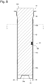
- Fig. 8 is a longitudinal cross-section view of the chamber 50 which includes the pressing part 62 and is in the state that the stick-type base material 150 is being held in the holding part 60.
- Fig. 9 is a cross-section view of the chamber 50, and relates to arrows 7-7 shown in Fig. 8 . It should be reminded that the cross section of the stick-type base material 150 to which no pressure has been applied is shown in Fig. 9 , to facilitate understanding of the process to apply pressure to the stick-type base material 150 by the pressing parts 62.
- a space 67, which is shown in Fig. 9 , positioned between the inner surface 66a of the non-pressing part 66 and the stick-type base material 150 is substantially maintained, even if the stick-type base material 150 is held in the holding part 60 and deformed as a result of application of pressure thereto by the pressing part 62.
- the space 67 can make the opening 52 of the chamber 50 and an the end surface, which is positioned in the chamber 50, of the stick-type base material 150 (the end surface shown in the lower center area in each of Fig. 7 and Fig. 8 , i.e., the end surface of the base material 151) communicate with each other.
- the space 67 can make the opening 52 of the chamber 50 and an the end surface, that is positioned in the chamber 50 and is distant from the opening 52 of the chamber 50, of the stick-type base material 150 (the end surface shown in the lower center area in each of Fig. 7 and Fig. 8 , i.e., the end surface of the base material 151) communicate with each other. Further, an air flow path from the opening 52 of the chamber 50 to an end surface, which is positioned in the outside of the chamber 50, of the stick-type base material 150 (the end surface shown in the upper center area in each of Fig. 7 and Fig.
- the height of the space 67 between the inner surface 66a of the non-pressing part 66 and the stick-type base material 150 is set preferably to that equal to or greater than 0.1 mm and equal to or less than 1.0 mm; more preferably, the height is set to that equal to or greater than 0.2 mm and equal to or less than 0.8 mm; and, most preferably, the height is set to that equal to or greater than 0.3 mm and equal to or less than 0.5 mm.
- the distance L A between the inner surface 62a of the pressing part 62 and the center of the stick-type base material 150 is shorter than the distance L B between the inner surface 66a of the non-pressing part 66 and the center of the stick-type base material 150.
- the distance between the heater 40, that is positioned on the outer surface 62b of the pressing part 62, and the center of stick-type base material 150 can be shortened, compared with the distance in the case that the pressing part 62 is not formed.
- heating efficiency in the stick-type base material 150 can be increased.
- the chamber 50 comprises a bottom part 56.
- the bottom part 56 supports, by a bottom wall 56a, a part of the stick-type base material 150 inserted into the chamber 50 in such a manner that at least a part of the end surface of the stick-type base material 150 is exposed, as shown in Fig. 8 .
- the bottom part 56 may support, by the bottom wall 56a, a part of the stick-type base material 150 in such a manner that the exposed end surface of the stick-type base material 150 communicates with the space 67.
- the bottom part 56 of the chamber 50 comprises the bottom wall 56a, and, in addition thereto, may comprise a side wall 56b. It may be possible to adopt a construction that the width, that depends on the side wall 56b, at a position in the bottom part 56 becomes smaller as the position approaches the bottom wall 56a closer.
- the inner surface 66a of the non-pressing part 66 in the holding part 60 is curved, in a plane perpendicular to the longitudinal direction of the chamber 50.
- the shape of the inner surface 66a of the non-pressing part 66 in the holding part 60 in a plane perpendicular to the longitudinal direction of the chamber 50 be identical to the shape of the opening 52 in a plane perpendicular to the longitudinal direction of the chamber 50.
- the inner surface 66a of the non-pressing part 66 be constructed by extending, in the longitudinal direction, the inner surface of the chamber 50 which forms the opening 52.
- the holding part 60 is provided with a state detector 69 for detecting the state of the stick-type base material 150 held in the holding part 60.
- the state detector 69 is arranged in a position on at least one surface of the pair of planar pressing surfaces in the inner surfaces 62a of the pressing parts 62, wherein the position is also that approximately in the center part in both the longitudinal and the lateral directions.
- the state detector 69 may be constructed by using a pressure sensor to measure contact pressure applied by the stick-type base material 150.
- the state detector 69 may be arranged in any position that is to be in contact with a part of the held stick-type base material 150.
- it may be arranged in a position in the bottom part 56 which supports a part of the stick-type base material 150.
- it may be possible to provide plural state detectors 69.
- the chamber 50 be provided with a non-holding part 54 which has a cylindrical shape and is in a position between the opening 52 and the holding part 60.
- a space may be formed in a position between the non-holding part 54 and the stick-type base material 150.
- the shape and the size of the outer peripheral surface of the holding part 60 (the length of the outer periphery of the holding part 60 in a plane perpendicular to the longitudinal direction of the holding part 60) be unchanged through the outer peripheral surface in the longitudinal direction of the holding part 60.
- the chamber 50 be provided with a first guide part 58 which comprises a tapered surface 58a which is connected to the inner surface of the chamber 50, which forms the opening 52 and the inner surface 62a of the pressing part 62.
- the heater 40 comprises a heating element 42.
- the heating element 42 may be a heating track, for example.
- the outer surface 62b of the pressing part 62 and the outer surface 66b of the non-pressing part 66 are connected with each other with an angle between them, and a border 71 is formed in a position between the outer surface 62b of the pressing part 62 and the outer surface 66b of the non-pressing part 66.
- the heating track extends in a direction that crosses a direction toward that the border 71 extends (the longitudinal direction of the chamber), and, preferably, extends in a direction perpendicular to the direction toward that the border 71 extends.
- the heater 40 be provided with, in addition to the heating element 42, an electrical insulation member 44 which covers at least one of surfaces of the heating element 42.
- the electrical insulation member 44 is arranged to cover the both surfaces of the heating element.
- the electrical insulation member 44 be arranged in a region on the outer surface of the holding part 60. In other words, it is preferable that the electrical insulation member 44 be arranged in a region along the longitudinal direction of the chamber 50 and on the side of the first guide part 58 in such a manner that it does not protrude from the outer surface of the holding part 60.
- the first guide part 58 is arranged in the position between the opening 52 and the pressing part 62, the shape of the outer surface of the chamber 50 and the length of the outer periphery of the chamber in a plane perpendicular to the longitudinal direction of the chamber may change in the longitudinal direction of the chamber 50.
- the electrical insulation member 44 is arranged on the outer surface of the holding part 60, and, accordingly, slackening can be prevented.
- the heater 40 is not arranged on at least one of the outer surface of the chamber 50 positioned between the opening 52 and the first guide part 58, i.e., the outer surface of the non-holding part 54, the outer surface of the first guide part 58, and the outer surface of the non-pressing part 66.
- the heater 40 is arranged on the overall outer surface 62b of the pressing part 62.
- the inhaler 100 comprises an electrode 48 that has a belt shape and extends from the heater 40.
- the belt-shaped electrode 48 extends toward the outside of the outer surface 62b, that is planar, of the pressing part 62 from the outer surface 62b of the pressing part 62.
- the heater 40 comprises a first part 40a which is in a position on a side opposite to the side of the opening 52, and a second part 40b which is in a position on the side of the opening 52. It is preferable that the heater power density in the second part 40b be higher than the heater power density in the first part 40a. Alternatively, it is preferable that the rate of temperature increase in the second part 40b be higher than the rate of temperature increase in the first part 40a. Alternatively, it is preferable that, at a given time, the heating temperature in the second part 40b be higher than the heating temperature in the first part 40a.
- the second part 40b covers the outer surface of holding part 60 in such a manner that the outer surface corresponding to a half or more than a half, in a longitudinal direction of a smokable article included in the stick-type base material 150, of the smokable article is covered.
- the chamber 50 comprises a pair of pressing parts 62 which face each other; however, the shape of the chamber is not limited to that explained above.
- the chamber 50 may comprise a single pressing part 62, or may comprise three or more pressing parts 62.
- the inhaler 100 holds the stick-type base material 150 by applying pressure thereto by the pressing part 62, and heats the stick-type base material 150.
- the thermal conductivity from the heater 40 to the stick-type base material 150 increases.
- the heating efficiency with respect to the stick-type base material 150 is improved. Since the heating efficiency with respect to the stick-type base material 150 is improved, the temperature of the stick-type base material 150 can be increased to target temperature quickly; accordingly, the length of time required for preheating, that will be explained later, can be shortened. Further, since the heating efficiency with respect to the stick-type base material 150 is improved, temperature followability of the stick-type base material 150 relating to temperature change in the heater 40 can be improved. As a result, first, controlling of the quantity of aerosol, that is to be generated, is further facilitated.
- the lowered temperature can be increased quickly to the original temperature.
- effect of external environment, such as ambient temperature and so on, thereon can be reduced.
- temperature change that is similar to temperature change defined in a heating profile, that will be explained later, can be realized easily in the stick-type base material 150.
- flavor enhancing effect that is the effect given during a temperature re-increasing section in a heating profile that will be explained later, can be provided quickly.
- the inhaler 100 heats the stick-type base material 150 from the outer periphery thereof while applying pressure thereto.
- improvement of heating efficiency with respect to the stick-type base material 150 and improvement of followability with respect to temperature of the stick-type base material 150 can be realized, independent of the shape of the aerosol source in the stick-type base material 150.
- improvement of heating efficiency with respect to the stick-type base material 150 and improvement of followability with respect to temperature of the stick-type base material 150 that has been explained above, can be realized, independent of errors with respect to the shape and the size of the stick-type base materials 150 that are included due to variation of the stick-type base materials 150 that occurs during the manufacturing process thereof.
- the heat insulator 70 is arranged to surround the heater 40 from the side of the outer periphery thereof.
- the outer surface 62b of the pressing part 62 arranged in a position is closer to the center of the inner space 80 than the position of the outer surface 66b of the non-pressing part 66 when the positions are compared with each other, the thickness of an air layer formed in a position between the outer surface 62b of the pressing part 62 and the heat insulator 70 can be made large.
- the thickness of the heat insulator 70 positioned on the pressing part 62 can be made large.
- heat insulating effect given by the heat insulator 70 can be improved.
- the inhaler 100 controls, based on a heating profile, operation of the heater 40 (i.e., heating operation).
- the inhaler 100 controls temperature of the heater 40 by controlling operation of the electric power source 111 for supplying electric power to the heater 40.
- the heating profile is an example of information that defines chronological change of target temperature that corresponds to target values of temperature of the heater 40.
- the heating profile is stored in the memory 114.
- the heating profile is referred to when heating operation of the heater 40 is performed for heating the stick-type base material 150. Further, instead of simply referring to the heating profile, it may be possible to change the heating profile during operation for heating the stick-type base material 150.
- aerosol is generated in accordance with a plan defined in the heating profile, in response to operation of the heater 40 in accordance with the heating profile.
- the heating profile is designed in such a manner that the flavor that a user tastes becomes the optimum state thereof when the user has performed an inhalation action.
- the controller 116 controls operation of the heater 40 based on a difference (separation) between target temperature defined in the heating profile and actual temperature of the heater 40 (hereinafter, this may be referred to as "actual temperature").
- the controller 116 controls operation of the electric power source 111 for supplying electric power to the heater 40, based on a separation between target temperature of the heater, that corresponds to time elapsed since the time of a start of control based on the heating profile for supplying electric power to the heater 40, and actual temperature of the heater 40.
- the controller 116 controls the temperature of the heater 40 in such a manner that chronological change of actual temperature of the heater 40 becomes the same as chronological change of target temperature of the heater 40 defined in the heating profile.
- the temperature control of the heater 40 can be realized by using publicly-known feedback control, for example.
- the controller 116 makes the electric power source 111 supply, to the heater 40, electric power in the forms of pulses generated by performing pulse width modulation (PWM) or pulse frequency modulation (PFM).
- PWM pulse width modulation
- PFM pulse frequency modulation
- the controller 116 can perform temperature control of the heater 40 by adjusting the duty ratio of the electric power pulse.
- the controller 116 may control, based on difference between the actual temperature and the target temperature or the like, electric power supplied from the electric power source 111 to the heater, for example, the above-explained duty ratio.
- the feedback control may be PID control (a Proportional-Integral-Differential Controller), for example.
- the controller 116 may perform simple ON-OFF control. For example, the controller 116 may instruct the electric power source 111 to make the heater 40 perform heating operation until actual temperature reaches target temperature, make the heater 40 stop heating operation in the case that actual temperature has reached target temperature, and make the heater 40 perform heating operation again when actual temperature has become that below target temperature.
- the temperature of the heater 40 can be determined, for example, by measuring or estimating the value of electric resistance of a heat-generating resistor which is included in the heater 40. This is because the electric resistance value of the heat-generating resistor changes according to temperature.
- the electric resistance value of the heat-generating resistor may be estimated by measuring the quantity of a voltage drop in the heat-generating resistor, for example.
- the quantity of the voltage drop in the heat-generating resistor can be measured by a voltage sensor for measuring a potential difference applied to the heat-generating resistor.
- the temperature of the heater 40 may be measured by using a temperature sensor arranged in a position close to the heater 40.
- the measured temperature of the heater 40 may be used in judgment with respect to puff action performed by a user.
- Heating based on the heating profile is started at timing when completion of manipulation representing an instructing for starting heating is detected.
- An example of manipulation representing an instructing for starting heating is pressing of a button constructed in the inhaler 100.
- the other example of manipulation representing an instructing for starting heating is a puff action.
- the other example of manipulation representing an instructing for starting heating is reception of a signal from the other device such as a smartphone or the like.
- the quantity of the aerosol source included in the base material gradually decreases as time elapses.
- heating operation performed by the heater 40 is stopped.
- An example of timing when the aerosol source is expected to be exhausted is timing when a predetermined period of time has elapsed since a start of controlling of operation of the heater 40 based on the heating profile.
- An example of timing when the aerosol source is expected to be exhausted is timing when a predetermined number of times of puffs is detected.
- An example of timing when the aerosol source is expected to be exhausted is timing when a button constructed in the inhaler 100 is pressed. For example, the above button is pressed when a user has felt that the user cannot taste flavor satisfactory.
- a period during that a sufficient quantity of aerosol is expected to be generated is also referred to as a puff allowable period.
- a period from a point in time when heating is started to a point in time when a puff allowable period starts is also referred to as a preheating period. Heating performed during the preheating period is also referred to as preheating.
- a user may be notified of timing when the puff allowable period starts and timing when it ends. In the above case, a user can use above notification for reference, and, based thereon, can perform puff action during the puff allowable period.
- the controller 116 controls operation of the heater 40, based on a holding state of the stick-type base material 150 held by the holding part 60.
- the controller 116 controls operation of the heater 40 to heat the stick-type base material 150 based on the heating profile, in the state that a part of the stick-type base material 150 is being pressed by the pressing part 62 in the holding part 60.
- the controller 116 controls heating of the stick-type base material 150 by the heater 40 in the state that a part of the stick-type base material 150 is being pressed by the pressing part 62 in the holding part 60, by adjusting the quantity of electric power supplied to the heater 40 in relation to target temperature corresponding to the length of time elapsed since the time when control of operation of the heater 40 based on the heating profile is started.
- the controller 116 may further adjust the quantity of supplied electric power in relation to the strength of pressure applied by the pressing part 62.
- the controller 116 may control operation of the heater 40 to prevent heating of the stick-type base material 150 based on the heating profile (for example, supplying of electric power to the heater 40 is stopped), in the state that no part of the stick-type base material 150 is pressed by the pressing part 62 in the holding part 60.
- the controller 116 may control operation of the heater 40 to prevent heating of the stick-type base material 150 based on the heating profile (for example, supplying of electric power to the heater 40 is stopped), in the state that no part of the stick-type base material 150 is pressed by the pressing part 62 in the holding part 60.
- the heating profile comprises plural consecutive time sections along a time axis. Each of the plural time sections is set in such a manner that it is associated with target temperature that is expected to be reached in an end stage in the time section.
- the controller 116 controls operation of the heater 40, based on a separation between actual temperature and target temperature relating to a time section, in the plural time sections, that corresponds to a period of time elapsed since controlling of operation of the heater 40 based on the heating profile is started.
- the controller 116 controls operation of the heater 40 in such a manner that the actual temperature reaches target temperature, that has been set to be related to each of the plural time sections included in the heating profile, before an end stage in the time section ends.
- Table 1 An example of the heating profile is shown in Table 1 below.
- Table 1 Example of Heating Profile Time Section Length of Time Target Temperature Initial Temperature-Increasing Section 35 seconds 295 °C Middle Temperature-Decreasing Section 10 seconds 230 °C Temperature Re-increasing Section 310 seconds 260 °C
- the heating profile shown in Table 1 comprises an initial temperature-increasing section, a middle temperature-decreasing section, and a temperature re-increasing section in this order.
- the initial temperature-increasing section is a section from a point in time when the heating profile is started to a point in time when 35 seconds has elapsed since the start of the heating profile.
- the middle temperature-decreasing section is a section from a point in time when the initial temperature-increasing section ends to a point in time when 10 seconds has elapsed since the end of the initial temperature-increasing section.
- the temperature re-increasing section is a section from a point in time when the middle temperature-decreasing section ends to a point in time when 310 seconds has elapsed since the end of the middle temperature-decreasing section.
- the initial temperature-increasing section is the time section included in a first part of the heating profile.
- the value of the target temperature that has been set to be related to the initial temperature-increasing section is higher than an initial value.
- the initial value is a value corresponds to temperature that is assumed as that of the heater 40 before starting of heating.
- An example of the initial value is 0 degree Celsius or the like, and the initial value can be selected arbitrarily.
- the other example of the initial value is a value corresponding to atmospheric temperature.
- the middle temperature-decreasing section is the time section included in the middle part of the heating profile.
- the target temperature that has been set to be related to the middle temperature-decreasing section is lower than the target temperature that has been set to be related to the time section just before the middle temperature-decreasing section.
- the target temperature specifically, 230 degrees Celsius
- the target temperature specifically, 295 degrees Celsius
- the temperature re-increasing section is the time section included in the end part of the heating profile.
- the target temperature that has been set to be related to the temperature re-increasing section is higher than the target temperature that has been set to be related to the time section just before the temperature re-increasing section.
- the target temperature specifically, 260 degrees Celsius
- the target temperature specifically, 230 degrees Celsius
- the middle temperature-decreasing section that is the time section just before the temperature re-increasing section.
- Fig. 10 is a graph which shows an example of chronological change in actual temperature of the heater 40 which was operated based on the heating profile shown in Table 1.
- the horizontal axis of the graph represents time (seconds).
- the vertical axis of the graph represents temperature of the heater 40.
- the line 21 in the graph represents chronological change in actual temperature of the heater 40.
- the actual temperature of the heater 40 has increased in the initial temperature-increasing section, and has reached 295 degrees Celsius, that is the target temperature, in the end stage in the initial temperature-increasing section.
- the temperature of the stick-type base material 150 reaches temperature that that makes it possible to generate a sufficient quantity of aerosol.
- the initial temperature-increasing section is set to be arranged in a first part in the heating profile.
- the heater 40 is heated to increase the temperature immediately from initial temperature to 295 degrees Celsius that is target temperature that has been set in relation to the initial temperature-increasing section.
- the initial temperature is actual temperature of the heater 40 at the time when heating based on the heating profile is started. According to the above construction, it becomes possible to terminate preheating in an early stage.
- the controller 116 performs, during the initial temperature-increasing section, temperature control of the heater 40 to change actual temperature to make it reach target temperature that has been set in relation to the initial temperature-increasing section. That is, the controller 116 controls temperature of the heater 40 to make it reach 295 degrees Celsius. If the actual temperature has reached 295 degrees Celsius before the elapse of 35 seconds from the start of heating, the controller 116 controls the temperature of the heater 40 to keep it at 295 degrees Celsius.
- the actual temperature of the heater 40 has decreased in the middle temperature-decreasing section, and has reached 230 degrees Celsius, that is target temperature, in an end stage in the middle temperature-decreasing section.
- the middle temperature-decreasing section is set to be arranged to follow the initial temperature-increasing section.
- the controller 116 makes the temperature drop temporarily from the set temperature relating to the initial temperature-increasing section to the set temperature relating to the middle temperature-decreasing section.
- the aerosol source included in the stick-type base material 150 may be consumed rapidly, and disadvantageous matters such that the flavor that is to be tasted by a user becomes excessively strong, and so on, may occur. That is, by adding the middle temperature-decreasing section, it becomes possible to avoid the above disadvantageous matters and improve the quality of puff experience of a user.
- the controller 116 performs control to stop supplying of electric power to the heater 40. That is, in the middle temperature-decreasing section, the controller 116 performs control to stop supplying of electric power to the heater 40 to prevent heating performed by the heater 40.
- the actual temperature of the heater 40 can be lowered at the fastest speed. Further, it becomes possible to reduce electric consumption of the inhaler 100, compared with that in a case wherein supplying of electric power to the heater 40 is performed during the middle temperature-decreasing section.
- the actual temperature of the heater 40 has increased during the temperature re-increasing section, and reached 260 degrees Celsius, that is target temperature, in an end stage in the temperature re-increasing section.
- the temperature re-increasing section is set to be arranged in a last part in the heating profile and follows the middle temperature-decreasing section.
- the heater 40 is heated again to increase the temperature from the set temperature relating to the middle temperature-decreasing section to the set temperature relating to the temperature re-increasing section.
- the heater 40 is controlled to make its temperature decrease continuously after completion of the initial temperature-increasing section, the temperature of the stick-type base material 150 also decreases; accordingly, the quantity of generated aerosol decreases, and the flavor that is to be tasted by a user may be deteriorated thereby. That is, by adding the temperature re-increasing section that follows the middle temperature-decreasing section, it also becomes possible to prevent deterioration of flavor, that is to be tasted by a user, in the latter half of the heating profile.
- the controller 116 performs, during the temperature re-increasing section, temperature control of the heater 40 to change actual temperature to make it reach target temperature that has been set in relation to the temperature re-increasing section. That is, the controller 116 controls temperature of the heater 40 to make it reach 260 degrees Celsius. If the actual temperature has reached 260 degrees Celsius before the elapse of 310 seconds from the start of the temperature re-increasing section, the controller 116 controls the temperature of the heater 40 to keep it at 260 degrees Celsius.
- the absolute vale with respect to the temperature re-increasing section may be the smallest
- the absolute vale with respect to the middle temperature-decreasing section may be the next smallest
- the absolute vale with respect to the initial temperature-increasing section may be the largest among them.
- the absolute vale of the quantity of change in target temperature per unit time with respect to the initial temperature-increasing section is a value obtained by dividing, by the time length of the initial temperature-increasing section, the absolute value of the difference between the initial value and the value of the target temperature that has been set in relation to the initial temperature-increasing section.
- the absolute vale of the quantity of change in target temperature per unit time with respect to the middle temperature-decreasing section is a value obtained by dividing, by the time length of the middle temperature-decreasing section, the absolute value of the difference between the target temperature that has been set in relation to the middle temperature-decreasing section and the target temperature that has been set in relation to a time section just before the middle temperature-decreasing section (for example, the initial temperature-increasing section).
- the absolute vale of the quantity of change in target temperature per unit time with respect to the temperature re-increasing section is a value obtained by dividing, by the time length of the temperature re-increasing section, the absolute value of the difference between the target temperature that has been set in relation to the temperature re-increasing section and the target temperature that has been set in relation to a time section just before the temperature re-increasing section (for example, the middle temperature-decreasing section).
- the middle temperature-decreasing section is the shortest
- the initial temperature-increasing section is the next shortest
- the temperature re-increasing section is the longest among them.
- the temperature of the heater 40 is rapidly increased in the initial temperature-increasing section, the heater 40 exits early from the high temperature state in the middle temperature-decreasing section, and the temperature of the heater 40 is slowly increased in the temperature re-increasing section.
- the controller 116 may perform, based on the actual temperature of the heater 40, determination with respect a part of switching operation for switching between plural time sections in the heating profile. For example, the controller 116 may perform determination with respect to switching from the initial temperature-increasing section to the middle temperature-decreasing section, and terminating of the temperature re-increasing section, based on whether a separation between the target temperature, that has been set in relation to each related time section, and the actual temperature of the heater 40 has become that in a predetermined threshold value range.
- the controller 116 may perform, based on time elapsed, determination with respect a part of switching operation for switching between plural time sections in the heating profile. For example, the controller 116 may determine the end of the middle temperature-decreasing section, based on the time elapsed since a start of the middle temperature-decreasing section. For example, in the heating profile shown in Fig. 10 , the length of the middle temperature-decreasing section is set to 10 seconds. Thus, the controller 116 determines switching to the temperature re-increasing section when 10 seconds has elapsed since a start of the middle temperature-decreasing section, and makes the heater 40 restart heating.
- switching from the middle temperature-decreasing section to the temperature re-increasing section can be performed without measuring temperature of the heater 40; thus, the processing load on the controller 116 can be reduced. Further, even in the case that a construction for measuring temperature of the heater 40 based on an electric resistance value of a heat-generating resistor included in the heater 40 is adopted, it becomes possible to determine switching to the temperature re-increasing section, while stopping supplying of electric power to the heater 40 in the middle temperature-decreasing section.
- the actual temperature of the heater 40 in the end stage of the middle temperature-decreasing section may change in relation to external environment, such as ambient temperature and so on.
- external environment such as ambient temperature and so on.
- the actual temperature of the heater 40 in the end stage of the middle temperature-decreasing section may become 220 degrees Celsius when ambient temperature is low, and may become 240 degrees Celsius when ambient temperature is high.
- operation of the heater 40 is controlled based on the actual temperature of the heater 40 and the target temperature that has been set in relation to the middle temperature-decreasing section.
- the controller 116 performs operation for supplying electric power to the heater 40 at a first duty ratio, in the first stage in the next time section following the middle temperature-decreasing section, if the actual temperature of the heater 40 is less than the target temperature that has been set in relation to the middle temperature-decreasing section.
- the controller 116 performs operation for supplying electric power to the heater 40 at a second duty ratio, in the first stage in the next time section following the middle temperature-decreasing section, if the actual temperature of the heater 40 is equal to or higher than the target temperature that has been set in relation to the middle temperature-decreasing section.
- the first duty ratio is higher than the second duty ratio.
- the duty ratio in the present case refers to a ratio of a period of time during that electric power is supplied to the heater 40 in a predetermined period.
- the separation can be reduced quickly, so that deterioration of flavor that is to be tasted by a user can be suppressed.
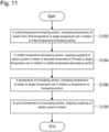
- Fig. 11 is a flow chart showing an example of the flow of processing performed by the inhaler 100.
- the inhaler 100 performs operation for increasing, in the initial temperature-increasing section, the temperature of the heater 40 from initial temperature to the target temperature that has been set in relation to the initial temperature-increasing section (step S102).
- the inhaler 100 performs, in the middle temperature-decreasing section, operation for stopping supplying of electric power to the heater 40 to decrease the temperature of the heater 40 to the target temperature that has been set in relation to the middle temperature-decreasing section (step S104).
- the inhaler 100 performs operation for increasing, in the temperature re-increasing section, the temperature of the heater 40 to the target temperature that has been set in relation to the temperature re-increasing section (step S 106). Thereafter, when the temperature re-increasing section ends, the inhaler 100 performs operation for stopping supplying of electric power to the heater 40 (step S108).
- Each of the initial temperature-increasing section, the middle temperature-decreasing section, and the temperature re-increasing section may comprise a temperature maintaining section for maintaining the temperature of the heater 40 at fixed temperature.
- An example of a heating profile in the above case is shown in Table 2. (Table 2) Table 2.
- Example of Heating Profile Time Section Length of Time Target Temperature Initial Temperature-Increasing Section Temperature Increasing Section 25 seconds 295 °C Temperature Maintaining Section 10 seconds 295 °C Middle Temperature-Decreasing Section Temperature Decreasing Section 10 seconds 230 °C Temperature Maintaining Section 135 seconds 230 °C Temperature Re-increasing Section Temperature Increasing Section 80 seconds 260 °C Temperature Maintaining Section 140 seconds 260 °C
- Fig. 12 is a graph which shows an example of chronological change in actual temperature of the heater 40 which was operated based on the example heat profile shown in Table 2.
- the horizontal axis of the graph represents time (seconds).
- the vertical axis of the graph represents temperature (degrees Celsius) of the heater 40.
- the line 22 in the graph represents chronological change in actual temperature of the heater 40.
- the initial temperature-increasing section is a section from a point in time when the heating profile starts to a point in time when 35 seconds has elapsed since the above start.
- the period of first 25 seconds in the initial temperature-increasing section is a temperature increasing section, and forms a time section for preheating for initially increasing the target temperature from 0 degree Celsius to 295 degrees Celsius.
- the period of last 10 seconds (that follows the temperature increasing section) is a temperature maintaining section for maintaining the target temperature at 295 degrees Celsius.
- the middle temperature-decreasing section that follows the initial temperature-increasing section, is a section from a point in time when the initial temperature-increasing section ends to a point in time when 145 seconds has elapsed since the above end.
- the period of first 10 seconds in the middle temperature-decreasing section is a temperature decreasing section, and the target temperature is decreased from 295 degrees Celsius to 230 degrees Celsius therein. Further, the period of last 135 seconds (that follows the temperature decreasing section) is a temperature maintaining section for maintaining the target temperature at 230 degrees Celsius.
- the temperature re-increasing section that follows the middle temperature-decreasing section, is a section from a point in time when the middle temperature-decreasing section ends to a point in time when 220 seconds has elapsed since the above end.
- the period of first 80 seconds in the temperature re-increasing section is a temperature increasing section, and the target temperature is again increased from 230 degrees Celsius to 260 degrees Celsius therein. Further, the period of last 140 seconds (that follows the temperature increasing section) is a temperature maintaining section for maintaining the target temperature at 260 degrees Celsius.
- the target temperature in the initial temperature-increasing section is 295 degrees Celsius
- the target temperature in the middle temperature-decreasing section is 230 degrees Celsius
- the target temperature in the temperature re-increasing section is 260 degrees Celsius
- the above temperatures constitute target temperatures (hereinafter, section's target temperatures) that are related to the above time sections, respectively.
- the section's target temperatures are defined in such a manner that they relate to time sections in the heating profile, respectively.
- one or plural values with respect to the section's target temperature/temperatures may be set. Further, it is not necessarily required to set target temperature in a first stage and target temperature in a last stage in a temperature maintaining section to have an identical value.
- the heating profile is constructed to include the above time sections, it becomes possible to provide a user with quality puff experience through the heating profile, i.e., from the start to the end of the heating profile.
- the temperature maintaining section is included in each of the initial temperature-increasing section, the middle temperature-decreasing section, and the temperature re-increasing section, it becomes possible to effectively increase, in the initial temperature-increasing section and the temperature re-increasing section, the temperature of the stick-type base material 150 including that of the inside part thereof. Further, it becomes possible to sufficiently decrease the temperature of the stick-type base material 150 including that of the inside part thereof, in the middle temperature-decreasing section. That is, it becomes possible to improve the quality of user's puff experience.
- the controller 116 in the inhaler 100 has a function for detecting puff action performed by a user, and controlling, based on the number of times of puff actions, heating operation with respect to the stick-type base material 150.
- the controller 116 in the inhaler 100 can perform operation for terminating heating operation, in response to detection of a predetermined number of times of puff actions.
- the air flows through the opening 52 into the space between the heater assembly 30 (which includes the heater 40) and the stick-type base material 150.
- the inflow air cools the heater 40, so that the temperature thereof is lowered.
- change in the quantity of air entering the inhaler 100 may be detected. That is, in an example, for detecting puff action performed by a user, it may be possible to consider adoption of a construction for detecting change in temperature of the heater 40 that occurs in relation to puff action performed by a user.
- change in temperature of a heating element can be detected by using any of various kinds of methods.
- change in temperature of a heating element can be detected by arranging a temperature sensor (thermistor) in a position close to the heating element.
- change in temperature of a heating element can be estimated by using the quantity of change in the electric resistance value of a heat-generating resistor, the quantity of change in the quantity of electric power supplied to the heating element, or the like.
- the quantity of change in detected temperature may not be stable always. That is, in the method for detecting puff action which adopts a process for detecting change in temperature, there is room for improvement in view of accuracy in terms of detection. Specifically, it has been know experimentally that there is a tendency that the variation width regarding the quantity of temperature change relating to a series of puff actions becomes smaller as the time elapsed since a start of heating by the heating element becomes longer.
- a further object of the inhaler 100 according to the present embodiment is to realize, by using a simple method, a method for accurately judging whether a puff action is performed by a user.
- Fig. 13 is a block diagram which functionally shows a construction of the controller 116 which performs a control method according to the present embodiment.
- the controller 116 included in the inhaler 100 comprises a supplying-of-power instructing unit 116a, a supplying-of-power controller 116b, a puff judgment unit 116c, a puff counting unit 116d, and a notification instructing unit 116e.
- the supplying-of-power instructing unit 116a instructs the electric power source 111 to start or stop supplying of electric power to the heater 40.
- the supplying-of-power controller 116b controls operation of the electric power source 111 for supplying electric power to the heater 40, to change the temperature to make it reach target temperature defined in the heating profile.
- the target temperature defined in the heating profile may be set in such a manner that target temperatures are set to correspond to time sections, respectively, wherein the respective time sections correspond to the respective lengths of time elapsed since a start of operation for supplying electric power. Examples of the time sections are the initial temperature-increasing section, the middle temperature-decreasing section, and the temperature re-increasing section that are shown in Fig. 10 and Fig. 12 .
- the supplying-of-power controller 116b performs operation for adjusting the temperature of the heater 40 to make the temperature of the heater 40 reach target temperature in an end stage in a corresponding time section. Adjusting of the temperature of the heater 40 may be realized by using the above-explained publicly known feedback control.
- the puff judgment unit 116c performs judgment as to whether a control value related to operation for supplying electric power satisfies a predetermined condition relating to change. In the case that the control value satisfies the predetermined change condition, it is judged that puff action is performed by a user.
- the control value is a value used by the supplying-of-power controller 116b in controlling of operation for supplying electric power, and, in the above-explained example, the control value may be a duty ratio of a pulse of electric power.
- the change condition with respect to the control value may be set as a condition that defines that the quantity of increase in the duty ratio is greater than a predetermined threshold value. That is, the puff judgment unit 116c judges that a puff action has been performed, in the case that the quantity of increase in the duty ratio used in controlling of operation for supplying electric power has become larger than a predetermined threshold value.
- the puff counting unit 116d counts, in heating control based on the heating profile, the number of puff actions performed by a user.
- the notification instructing unit 116e instructs the notifier 113 to perform predetermined notification operation. For example, in response to a judgment that is made by the puff judgment unit 116c and indicates that a puff action has been performed by a user, the notification instructing unit 116e makes the notifier 113 perform notification operation for informing the above matter.
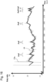
- Each of Fig. 14 and Fig. 15 is a graph which shows an example of chronological change in the duty ratio in controlling of operation for supplying electric power.
- the graph shown in Fig. 14 represents the overall chronological change in the duty ratio, and an enlarged graph that corresponds to a part encircled by a broken line in Fig. 14 is shown in Fig. 15 .
- the horizontal axis represents time (seconds), and the vertical axis represents the duty ratio (%) of the electric power pulse.
- each graph corresponds to the heating profile shown in Fig. 10 .
- the supplying-of-power controller 116b controls operation for supplying electric power, by determining the duty ratio in real time by using feedback control.
- the air flowing through the opening 52 cools the heater 40.
- the temperature of the heater 40 decreases.
- supplying-of-power controller 116b makes compensation for the decrease in temperature of the heater, by performing feedback control of supplied electric power.
- the supplying-of-power controller 116b controls operation for supplying electric power in such a manner that, while the electric power is supplied from the electric power source 111 to the heater 40, the duty ratio of the electric power pulse is adjusted according to pulse width modulation (PWM) control. Further, in the case that the temperature of the heater 40 is decreased, the supplying-of-power controller 116b performs operation for temporarily increasing the temperature of the heater 40 by increasing the duty ratio of the electric power pulse, and, further, making the temperature reach the target temperature defined in the heating profile. Since the above the operation comprises contents such as those explained above, the duty ratio can be represented as a wave form that is shown by the line 23 in the graph in Fig. 14 and relates to puff action performed by a user.
- PWM pulse width modulation
- a predetermined threshold value has been set as a change condition and associated with the duty ratio in advance. Further, when a change condition such as that explained above is satisfied (especially, when the quantity of increase in the duty ratio has exceeded a threshold value), the puff judgment unit 116c can judge that a user's puff action has performed.
- a change condition such as that explained above is satisfied (especially, when the quantity of increase in the duty ratio has exceeded a threshold value)
- the quantity of increase in the duty ratio may be calculated by obtaining difference between a smallest value (minimum value) and a largest value (maximum value) in a predetermined length of time.
- the threshold value may be set to a value that is experimentally defined. Further, the threshold value may be set during a manufacturing process, or at any timing after completion of the manufacturing process. For example, a condition that the duty ratio goes up 20% or more in one second may be set as the change condition, and a judgment indicating the matter that a puff action has been performed may be made when the above condition is satisfied.
- the change condition may be set in such a manner that it is associated with the time elapsed since a start of operation for supplying electric power.
- time sections such as the initial temperature-increasing section, the middle temperature-decreasing section, and the temperature re-increasing section
- different change conditions may be set and related to different time sections, respectively.
- the change condition be set in such a manner that the ratio of increase in the duty ratio for compensating for decrease in temperature of the heater 40 by feedback control becomes smaller as the time elapsed since a start of operation for supplying electric power becomes longer.
- a condition that the duty ratio goes up “30%” or more may be associated with the initial temperature-increasing section, a condition that the duty ratio goes up “25%” or more may be associated with the middle temperature-decreasing section, and a condition that the duty ratio goes up "20%” or more may be associated with the temperature re-increasing section.
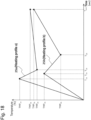
- Fig. 16 is a graph which shows an example of chronological change in the moving average of the duty ratio in operation for supplying electric power.
- the line 24 in the graph shown in Fig. 16 shows an example of chronological change in the moving average that corresponds to the chronological data of the duty ratio represented by the line 23a in the graph in Fig. 15 .
- the line 24 in the graph is shown in such a manner that the line 24 is superimposed on the line 23a in the graph in Fig. 15 .
- the moving average has been generally known as a method for making chronological data smooth.
- average values of fixed sections are obtained, respectively, and chronological change in the average is shown.
- any moving average method such as a simple moving average method, a weighted moving average method, an exponential moving average method, or the like may be used in the present embodiment.
- the ratio of increase in the moving average value with respect to the chronological data of the duty ratio may be applied in relation to the quantity of increase in the above-explained duty ratio.
- an average value of the duty ratio for each predetermined section for example, 1 second
- a judgment as to whether the average value of the duty ratio has went up 20% or more during a period including consecutive plural sections is made.
- the puff judgment unit 116c can judge that a user's puff action has been performed. That is, by judging occurrence of a user's puff action by using the rate of increase in the moving average value relating to the chronological data of the duty ratio, it becomes possible to avoid misjudgment and make the accuracy of judgment more stable.
- Fig. 17 is a flow chart which shows an example of the flow of processing in a control method according to the present embodiment. Specifically, heating control relating to an aerosol source is performed based on the heating profile; that is, an example of the flow of processing, that is performed when control of operation for supplying electric power is being performed, for judging whether user's puff action has been performed will be shown.
- the processes in the present embodiment are performed by the controller 116.
- the controller 116 first makes the sensor 112 detect a request for inhalation.
- the supplying-of-power instructing unit 116a instructs the electric power source 111 to start supplying of electric power to the heater 40 (step S11).
- the inhalation request corresponds to user manipulation performed by a user for requesting generating of aerosol.
- An example of the inhalation request is user manipulation applied to the inhaler 100, such as an action of a user for pressing a button installed in the inhaler 100.
- the other example of the inhalation request is an action of a user for inserting the stick-type base material 150 into the inhaler 100.
- Detecting of a state that the stick-type base material 150 is being held by the holding part 140 may be performed by a pressure sensor installed in the holding part 140 by detecting contact pressure between the pressure sensor and the held stick-type base material 150.
- the pressure sensor arranged on an inner surface of the holding part 140 and the outer periphery of the stick-type base material 150 are brought into contact with each other.
- the controller 116 makes the pressure sensor detect the contact pressure, so that a judgement indicating the state that stick-type base material 150 is being held by the holding part 140 can be made.
- the state that stick-type base material 150 is being held by the holding part 140 may be detected by using a capacitance-type proximity sensor arranged in a position near the opening 142, i.e., it may be detected based on change in capacitance or permittivity that is observed in relation to insertion of the stick-type base material 150 into the inside.
- the capacitance-type proximity sensor arranged in a position near the opening 142 detects capacitance, permittivity, or the like in a subspace near the opening 142 in the inner space 141. In relation to inserting/extracting of the stick-type base material 150, various kinds of parts of the stick-type base material 150 pass through the subspace.
- the controller 116 can make a judgment indicating the state that the stick-type base material 150 is being held by the holding part 140, according to chronological change in capacitance or permittivity in a subspace such as that explained above.
- the supplying-of-power controller 116b performs operation for starting heating control that relates to the aerosol source and is based on the heating profile, that is, starts control of operation for supplying electric power (step S12). After step S12, the heating control performed by the supplying-of-power controller 116b is continued until control for supplying electric power is terminated in step S18.
- the supplying-of-power controller 116b continuously measures the temperature of the heater 40 for heating control based on the heating profile (step S13).
- the temperature of the heater 40 can be measured by using the quantity of change in the value of the quantity of electric power supplied to the heater 40 or the electric resistance value of the heat-generating resistor.
- the temperature of the heater 40 measured in step S13 is controlled based on the heating profile that defines chronological change in target temperature of the heater 40. That is, the supplying-of-power controller 116b adjusts, based on the heating profile, the control value relating to operation for supplying electric power in such a manner that the temperature of the heater 40 is adjusted to reach the target temperature (step S14).
- target temperatures may be set to correspond to time sections, respectively, wherein the respective time sections correspond to the respective lengths of time elapsed since a start of operation for supplying electric power.
- the control value be adjusted in such a manner that the temperature of the heater 40 reaches a target temperature in an end stage in a time section corresponding to a length of elapsed time.
- the control value may be a duty ratio of an electric power pulse, and the duty ratio of the electric power pulse may be adjusted by using pulse width modulation (PWM) control.
- PWM pulse width modulation
- the puff judgment unit 116c judges that a puff action has been performed, if the control value used in step S14 satisfies a predetermined change condition (step S15).
- a predetermined change condition that the control value may satisfy is a condition that the quantity of increase in the duty ratio is larger than a predetermined threshold value.
- step S15 If it is judged in step S15 that a puff action has been performed (Yes), the puff counting unit 116d increments the number of times of puff actions performed by a user (step S16). On the other hand, if it is judged in step S15 that no puff action has been performed (No), step S16 is skipped.
- the controller 116 repeats steps S13-S16 until a condition for terminating control is satisfied (step S17).
- the termination condition may be a condition that the number of times of puff actions counted in step S16 in the period of the heating control reaches a predetermined number of times. It should be reminded that the termination condition is not limited to that explained above, and, in a different example, it may be a condition that the period of time during that the heating control was performed (i.e., the length of time of heating) exceeds a predetermined length of time.
- step S17 if it is judged in step S17 by the supplying-of-power controller 116b that the condition for terminating the heating control has been satisfied (Yes), the heating control based on the heating profile, i.e., control of operation for supplying electric power is terminated (step S18).
- the notification instructing unit 116e may make the notifier 113 output notification with respect to above termination.
- step S18 Thereafter, i.e., after terminating of the heating control in step S18, the present processing is terminated.
- puff action performed by a user can be incorporated, as a part in information processing, in the information processing realized by software. That is, it becomes possible to provide a method for judging whether a puff action has been performed, by using a simple method that does not require installation of a dedicated sensor in a device. As a result, disadvantages relating to manufacture, such as increasing of the size of the inhaler, increasing of the cost for manufacturing the inhaler, and so on, can be suppressed.
- the control value (for example, the duty ratio of the electric power pulse) used by the controller 116 in control of operation for supplying electric power from the electric power source 111 to the heater 40 can be applied as it stands as a parameter for judging a puff action. That is, puff action performed by a user can be judged in a simplified and accurate manner, for judging whether a puff action is performed by the user.
- heating control of an aerosol source i.e., control of operation for supplying electric power
- a single heating profile plural kinds of heating profiles may be set in advance, and control processing based on each of the heating profiles may be performed.
- the condition for judging whether puff action has been performed may be set flexibly in relation to each of the heating profiles.
- each of the heating profiles a and b comprises an initial temperature-increasing section, a middle temperature-decreasing section, and a temperature re-increasing section.
- the chronological change in target temperature of the heater 40 defined in the heating profile a is different from that defined in the heating profile b. Examples of the above heating profiles a and b are shown in Table 3-1 and Table 3-2.
- Fig. 18 is a graph which shows examples of chronological change in actual temperature of the heater 40 which was operated based on heat profiles a and b shown above.
- the horizontal axis of the graph represents time (seconds).
- the vertical axis of the graph represents temperature (degrees Celsius) of the heater 40.
- the lines 25a and 25b in the graph represent chronological change in actual temperature of the heater 40.
- the length of time of each section and the target temperature in each section relating to the heating profile a are different from those relating to the heating profile b.
- the heating profile a is set in such a manner that the temperature of the hater 40 becomes relatively higher through the whole part thereof, compared with that relating to the heating profile b.
- a change condition that is different from that related to the heating profile a may be related to the heating profile b. That is, a change condition A may be related to the chronological change in the heating profile a, and a change condition B, that is different from the change condition A, may be related to the chronological change in the heating profile b.
- the temperature of the heater 40 operated in relation to the chronological change in the higher-temperature heating profile changes in a temperature range higher than a temperature range of change in the temperature of the heater 40 operated in relation to the chronological change in the lower-temperature heating profile.
- the above matter means that the temperature difference between the temperature of the heater 40 and the temperature of the air taken in as a result of user's puff action becomes large. That is, the quantity of the temperature fall relating to a puff action becomes large when the chronological change in the higher-temperature heating profile is adopted, compared with that in the case that the chronological change in the lower-temperature heating profile is adopted.
- the corresponding change condition A be set more strict than the change condition B.
- the matter that the change condition A is more strict than the change condition B includes, for example, the matter that the threshold value associated with the change condition A is set to that larger than that associated with the change condition B.
- a judgment method based on change in the control value (the duty ratio) used in operation for supplying electric power is adopted.
- a different method based on change in temperature of the heater 40 is also adopted, i.e., two methods relating to judgment with respect to puff action are adopted together.
- the puff judgment unit 116c in the controller 116 performs, based on change in temperature of the heater 40, judgment with respect to user's puff action.
- the temperature of the heater 40 is measured by the sensor 112 which is a component of a temperature measuring part. That is, the puff judgment unit 116c is constructed to be able to make a judgment indicating a performed puff action in the case that the temperature of the heater 40 has satisfied a predetermined temperature change condition.
- the temperature of the heater 40 can be measured by arranging, for example, a temperature sensor (thermistor) in a position neat the heater 40, and change in the temperature of the heater 40 can be determined by using measured temperature. Further, instead of using a thermistor, it is possible to install a voltage sensor to detect an electric resistance value of a heat-generating resistor or the quantity of electric power supplied to a heating element, and, based on the quantity of change thereof, determine change in the temperature of the sensor 40. That is, it is possible to adopt a method for judging, based on determination as to whether the temperature of the heater 40 satisfies a predetermined temperature change condition, user's puff action.
- a temperature sensor thermometer
- chronological change of target temperature of the heater 40 in the heating profile is related to at least two sections.
- the above sections comprises a first-half section that corresponds to a period from a point in time when operation for supplying electric power starts to a point in time when a predetermined length of time has elapsed, and a latter-half section that corresponds to a period from a point in time when the first-half section ends to a point in time when a predetermined length of time has elapsed since the end of the first-half section.
- the puff judgment unit 116c performs judgment with respect to puff action, based on the temperature of the heater 40, i.e., according to determination as to whether the temperature of the heater 40 satisfies the temperature change condition.
- the puff judgment unit 116c performs judgment with respect to puff action, according to determination as to whether the duty ratio satisfies the change condition.
- the first-half section may be defined as that comprising the initial temperature-increasing section and the middle temperature-decreasing section, and the latter-half section may be defined as that comprising the temperature re-increasing section.
- the initial temperature-increasing section is a section for preheating the heater 40 after starting of operation for supplying electric power.
- the middle temperature-decreasing section is a section following the initial temperature-increasing section, and, during that the temperature of the heater 40 is reduced by stopping the operation for supplying electric power.
- the temperature re-increasing section is a section during that the heater is heated again by resuming the operation for supplying electric power.
- Fig. 19 is a flow chart which shows an example of the flow of control processing that is realized by applying the present modification example thereto.
- the present flow chart can be applicable as a modification example of step S15 in the flow chart in Fig. 17 that has been explained in relation to the above-explained embodiment.
- step S150a judgment as to whether a section, that corresponds to the length of time elapsed until the present time since a start of control of operation for supplying electric power to the heater 40, is either one of the initial temperature-increasing section and the middle temperature-decreasing section (step S150a). If the time elapsed until the present time is that in the range of the initial temperature-increasing section or the middle temperature-decreasing section (Yes), operation for judging, based on the temperature of the heater 40, whether puff action has been performed is performed.
- the puff judgment unit 116c may perform operation for judging whether the temperature of the heater 40 satisfies a temperature change condition (step S150b), and, if the temperature satisfies the temperature change condition (Yes), make a judgment indicating a performed puff action (step S150d).
- step S150a if a section corresponding to the present elapsed time is the temperature re-increasing section (step S150a: No), operation for judging, based on the duty ratio, whether puff action has been performed is performed. That is, the puff judgment unit 116c may perform operation for judging whether the duty ratio satisfies a predetermined change condition (step S150c), and, if the duty ratio satisfies the predetermined change condition (Yes), make a judgment indicating a performed puff action (step S150d).
- a third modification example Similar to the second modification example, two methods relating to judgment with respect to puff action are used together in a third modification example; wherein a different method based on change in temperature of the heater 40 is adopted therein.
- the method for judging, based on change in the duty ratio, whether puff action has been performed and the method for judging (detecting), based on change in the temperature of the heater 40, whether puff action has been performed are performed at the same time.
- the puff judgment unit 116c may make a judgment indicating performed puff action, in either one of or both the case that the duty ratio satisfies a predetermined change condition and the case that the temperature of the heater 40 satisfies a predetermined temperature change condition.
- the above two methods are performed concurrently, and a puff action performed by a user may actually be specified in the case that a judgment indicating a performed puff action is made based on one method and the same judgment is also made based on the other method.
- the above two methods are also performed concurrently, and puff action performed by a user may actually be specified in the case that the puff judgment unit 116c has made, based either one of the two method, a judgment indicating a performed puff action.
- plural methods for the judgment process with respect to puff action are prepared, and the plural methods can be used concurrently when performing the judgment process with respect to puff action.
- accuracy of judgment with respect to puff action can be further improved.
- puff action performed by a user can be incorporated, as a part in information processing, in the information processing realized by software. That is, it becomes possible to provide a method for making a judgment with respect to puff action, by using a simple method that does not require installation of a dedicated sensor in a device.
- disadvantages relating to manufacture such as increasing of the size of the inhaler 100, increasing of the cost for manufacturing the inhaler 100, and so on, can be suppressed.
- the control value (for example, the duty ratio of the electric power pulse) used by the controller 116 in control of operation for supplying electric power from the electric power source 111 to the heater 40 can be applied as it stands as a parameter for making a judgment with respect to puff action. That is, judgment as to whether a puff action has been performed by a user can be performed in a simplified and accurate manner, for judgment with respect to a puff action performed by the user.
- each program is read into a RAM when a computer, which controls each device explained in the present specification, is operated, and is executed by a processor such as a CPU.
- the storage medium is, for example, a magnetic disk, an optical disk, a magneto-optical disk, a flash memory, or the like.
- the computer program may be delivered via a network without using a storage medium, for example.
Landscapes
- Health & Medical Sciences (AREA)
- Engineering & Computer Science (AREA)
- Life Sciences & Earth Sciences (AREA)
- Animal Behavior & Ethology (AREA)
- Anesthesiology (AREA)
- Biomedical Technology (AREA)
- Heart & Thoracic Surgery (AREA)
- Hematology (AREA)
- Veterinary Medicine (AREA)
- Public Health (AREA)
- General Health & Medical Sciences (AREA)
- Pulmonology (AREA)
- Bioinformatics & Cheminformatics (AREA)
- Resistance Heating (AREA)
- Thermotherapy And Cooling Therapy Devices (AREA)
- Sampling And Sample Adjustment (AREA)
Applications Claiming Priority (1)
| Application Number | Priority Date | Filing Date | Title |
|---|---|---|---|
| PCT/JP2021/040020 WO2023073920A1 (ja) | 2021-10-29 | 2021-10-29 | 吸引装置、基材、及び吸引装置の制御方法 |
Publications (2)
| Publication Number | Publication Date |
|---|---|
| EP4424185A1 true EP4424185A1 (de) | 2024-09-04 |
| EP4424185A4 EP4424185A4 (de) | 2025-09-10 |
Family
ID=86157634
Family Applications (1)
| Application Number | Title | Priority Date | Filing Date |
|---|---|---|---|
| EP21962462.4A Pending EP4424185A4 (de) | 2021-10-29 | 2021-10-29 | Saugvorrichtung, substrat und steuerungsverfahren der saugvorrichtung |
Country Status (7)
| Country | Link |
|---|---|
| US (1) | US20240277076A1 (de) |
| EP (1) | EP4424185A4 (de) |
| JP (1) | JP7671363B2 (de) |
| KR (1) | KR20240095443A (de) |
| CN (1) | CN118159161A (de) |
| TW (1) | TW202316987A (de) |
| WO (1) | WO2023073920A1 (de) |
Families Citing this family (5)
| Publication number | Priority date | Publication date | Assignee | Title |
|---|---|---|---|---|
| US12520880B2 (en) | 2021-01-18 | 2026-01-13 | Altria Client Services Llc | Heat-not-burn (HNB) aerosol-generating devices including energy based heater control, and methods of controlling a heater |
| US12550942B2 (en) | 2022-09-19 | 2026-02-17 | Altria Client Services Llc | Session control system |
| US20240398038A1 (en) * | 2023-06-05 | 2024-12-05 | Altria Client Services Llc | Aerosol-generating devices and methods for generating aerosol |
| CN119908519A (zh) * | 2023-10-31 | 2025-05-02 | 深圳市合元科技有限公司 | 控制方法及气溶胶生成装置 |
| CN121153933A (zh) * | 2024-06-17 | 2025-12-19 | 思摩尔国际控股有限公司 | 一种加热不燃烧装置及其抽吸检测方法 |
Family Cites Families (17)
| Publication number | Priority date | Publication date | Assignee | Title |
|---|---|---|---|---|
| JPS6357060A (ja) * | 1986-08-27 | 1988-03-11 | オムロン株式会社 | 吸入器 |
| MX367721B (es) | 2011-12-30 | 2019-09-03 | Philip Morris Products Sa | Dispositivo generador de aerosol con deteccion de flujo de aire. |
| MY175490A (en) * | 2013-09-30 | 2020-06-30 | Japan Tobacco Inc | Non-burning type flavor inhaler |
| US10179215B2 (en) | 2015-03-19 | 2019-01-15 | Altria Client Services Llc | Vaporizer for vaporizing a constituent of a plant material |
| EP3387923B1 (de) | 2017-02-16 | 2020-01-29 | SMISS Technology Co., Ltd | Elektronische zigarettenvorrichtung und verfahren zur berechnung der anzahl der züge |
| KR102843313B1 (ko) * | 2017-06-28 | 2025-08-07 | 알트리아 클라이언트 서비시즈 엘엘씨 | 증발 장치 및 이를 이용한 화합물 전달 방법 |
| KR102451855B1 (ko) | 2018-03-26 | 2022-10-07 | 니뽄 다바코 산교 가부시키가이샤 | 에어로졸 생성 장치 및 제어 방법 및 기억 매체 |
| CN111936001B (zh) * | 2018-03-26 | 2023-11-28 | 日本烟草产业株式会社 | 气雾剂产生设备、控制方法和程序 |
| KR102532401B1 (ko) * | 2018-04-26 | 2023-05-15 | 니뽄 다바코 산교 가부시키가이샤 | 히터 어셈블리 및 용기 |
| JP7496315B2 (ja) | 2018-10-26 | 2024-06-06 | 日本たばこ産業株式会社 | 制御ユニット、エアロゾル生成装置、ヒータを制御する方法及びプログラム |
| WO2020084756A1 (ja) * | 2018-10-26 | 2020-04-30 | 日本たばこ産業株式会社 | 電子装置並びに電子装置を動作させる方法及びプログラム |
| KR102306051B1 (ko) | 2018-11-16 | 2021-09-28 | 주식회사 케이티앤지 | 에어로졸을 발생 장치 및 에어로졸을 발생 장치의 제어 방법 및 그 장치 |
| US11980231B2 (en) | 2019-01-15 | 2024-05-14 | Kt&G Corporation | Aerosol generating system and method of operating the same |
| KR102252456B1 (ko) * | 2019-04-18 | 2021-05-14 | 주식회사 케이티앤지 | 퍼프 횟수를 카운트하는 방법 및 이를 적용한 에어로졸 생성 장치 |
| KR102278590B1 (ko) * | 2019-04-18 | 2021-07-16 | 주식회사 케이티앤지 | 에어로졸 생성 장치 및 그의 동작 방법 |
| US11918050B2 (en) * | 2020-01-22 | 2024-03-05 | Altria Client Services Llc | Hot wire anemometer air flow measurement, puff detection and ambient temperature tracking |
| CN113519918A (zh) | 2021-06-25 | 2021-10-22 | 深圳麦时科技有限公司 | 气溶胶形成装置及其抽吸检测方法、计算机存储介质 |
-
2021
- 2021-10-29 WO PCT/JP2021/040020 patent/WO2023073920A1/ja not_active Ceased
- 2021-10-29 CN CN202180103739.3A patent/CN118159161A/zh active Pending
- 2021-10-29 JP JP2023556027A patent/JP7671363B2/ja active Active
- 2021-10-29 EP EP21962462.4A patent/EP4424185A4/de active Pending
- 2021-10-29 KR KR1020247017977A patent/KR20240095443A/ko active Pending
-
2022
- 2022-04-13 TW TW111114055A patent/TW202316987A/zh unknown
-
2024
- 2024-04-29 US US18/648,518 patent/US20240277076A1/en active Pending
Also Published As
| Publication number | Publication date |
|---|---|
| KR20240095443A (ko) | 2024-06-25 |
| CN118159161A (zh) | 2024-06-07 |
| JP7671363B2 (ja) | 2025-05-01 |
| WO2023073920A1 (ja) | 2023-05-04 |
| JPWO2023073920A1 (de) | 2023-05-04 |
| US20240277076A1 (en) | 2024-08-22 |
| EP4424185A4 (de) | 2025-09-10 |
| TW202316987A (zh) | 2023-05-01 |
Similar Documents
| Publication | Publication Date | Title |
|---|---|---|
| EP4424185A1 (de) | Saugvorrichtung, substrat und steuerungsverfahren der saugvorrichtung | |
| JP7637695B2 (ja) | 吸引装置、制御方法、及びプログラム | |
| US20240108823A1 (en) | Inhalation device, base material, and control method | |
| US12588713B2 (en) | Inhalation device, control method, and non-transitory computer readable medium | |
| US20240090590A1 (en) | Inhalation device, substrate, and control method | |
| US20240196988A1 (en) | Inhalation device, substrate, and control method | |
| JP7641984B2 (ja) | 吸引装置、制御方法、及びプログラム | |
| US20250000171A1 (en) | Aerosol generation system, control method, and non-transitory computer readable medium | |
| KR20240144360A (ko) | 에어로졸 생성 시스템, 제어 방법 및 프로그램 | |
| WO2023181280A1 (ja) | エアロゾル生成システム、制御方法、及びプログラム | |
| EP4666889A1 (de) | Aerosolerzeugungssystem und steuerungsverfahren | |
| EP4674295A1 (de) | Aerosolerzeugungssystem, steuerungsverfahren und nichttransitorisches speichermedium | |
| EP4563024A1 (de) | Aerosolerzeugungssystem, steuerungsverfahren und programm | |
| EP4559336A1 (de) | Aerosolerzeugungssystem, steuerungsverfahren und programm | |
| KR20250140116A (ko) | 에어로졸 생성 시스템, 제어 방법, 및 컴퓨터 판독 가능한 매체에 저장된 프로그램 | |
| EP4427615A1 (de) | Aerosolerzeugungssystem, steuerungsverfahren und programm | |
| EP4523557A1 (de) | Aerosolerzeugungssystem und steuerungsverfahren | |
| WO2024171266A1 (ja) | エアロゾル生成装置の電源ユニット、及び、エアロゾル生成装置 |
Legal Events
| Date | Code | Title | Description |
|---|---|---|---|
| STAA | Information on the status of an ep patent application or granted ep patent |
Free format text: STATUS: THE INTERNATIONAL PUBLICATION HAS BEEN MADE |
|
| PUAI | Public reference made under article 153(3) epc to a published international application that has entered the european phase |
Free format text: ORIGINAL CODE: 0009012 |
|
| STAA | Information on the status of an ep patent application or granted ep patent |
Free format text: STATUS: REQUEST FOR EXAMINATION WAS MADE |
|
| 17P | Request for examination filed |
Effective date: 20240327 |
|
| AK | Designated contracting states |
Kind code of ref document: A1 Designated state(s): AL AT BE BG CH CY CZ DE DK EE ES FI FR GB GR HR HU IE IS IT LI LT LU LV MC MK MT NL NO PL PT RO RS SE SI SK SM TR |
|
| DAV | Request for validation of the european patent (deleted) | ||
| DAX | Request for extension of the european patent (deleted) | ||
| REG | Reference to a national code |
Ref country code: DE Ref legal event code: R079 Free format text: PREVIOUS MAIN CLASS: A24F0040530000 Ipc: A24F0040510000 |
|
| A4 | Supplementary search report drawn up and despatched |
Effective date: 20250808 |
|
| RIC1 | Information provided on ipc code assigned before grant |
Ipc: A24F 40/51 20200101AFI20250804BHEP Ipc: A24F 40/50 20200101ALI20250804BHEP Ipc: A61M 11/04 20060101ALI20250804BHEP Ipc: A61M 15/06 20060101ALI20250804BHEP Ipc: G01F 1/68 20060101ALI20250804BHEP Ipc: A24F 40/57 20200101ALN20250804BHEP Ipc: A24F 40/46 20200101ALN20250804BHEP Ipc: A24F 40/20 20200101ALN20250804BHEP |