EP4424232A1 - Dispositif électronique pour déterminer un signe vital d'un utilisateur et son procédé de fonctionnement - Google Patents
Dispositif électronique pour déterminer un signe vital d'un utilisateur et son procédé de fonctionnement Download PDFInfo
- Publication number
- EP4424232A1 EP4424232A1 EP23740471.0A EP23740471A EP4424232A1 EP 4424232 A1 EP4424232 A1 EP 4424232A1 EP 23740471 A EP23740471 A EP 23740471A EP 4424232 A1 EP4424232 A1 EP 4424232A1
- Authority
- EP
- European Patent Office
- Prior art keywords
- vital sign
- sensor
- user
- electronic device
- heart rate
- Prior art date
- Legal status (The legal status is an assumption and is not a legal conclusion. Google has not performed a legal analysis and makes no representation as to the accuracy of the status listed.)
- Pending
Links
Images


Classifications
-
- A—HUMAN NECESSITIES
- A61—MEDICAL OR VETERINARY SCIENCE; HYGIENE
- A61B—DIAGNOSIS; SURGERY; IDENTIFICATION
- A61B5/00—Measuring for diagnostic purposes; Identification of persons
- A61B5/68—Arrangements of detecting, measuring or recording means, e.g. sensors, in relation to patient
- A61B5/6801—Arrangements of detecting, measuring or recording means, e.g. sensors, in relation to patient specially adapted to be attached to or worn on the body surface
- A61B5/6802—Sensor mounted on worn items
- A61B5/681—Wristwatch-type devices
-
- A—HUMAN NECESSITIES
- A61—MEDICAL OR VETERINARY SCIENCE; HYGIENE
- A61B—DIAGNOSIS; SURGERY; IDENTIFICATION
- A61B5/00—Measuring for diagnostic purposes; Identification of persons
-
- A—HUMAN NECESSITIES
- A61—MEDICAL OR VETERINARY SCIENCE; HYGIENE
- A61B—DIAGNOSIS; SURGERY; IDENTIFICATION
- A61B5/00—Measuring for diagnostic purposes; Identification of persons
- A61B5/02—Detecting, measuring or recording for evaluating the cardiovascular system, e.g. pulse, heart rate, blood pressure or blood flow
- A61B5/0205—Simultaneously evaluating both cardiovascular conditions and different types of body conditions, e.g. heart and respiratory condition
-
- A—HUMAN NECESSITIES
- A61—MEDICAL OR VETERINARY SCIENCE; HYGIENE
- A61B—DIAGNOSIS; SURGERY; IDENTIFICATION
- A61B5/00—Measuring for diagnostic purposes; Identification of persons
- A61B5/02—Detecting, measuring or recording for evaluating the cardiovascular system, e.g. pulse, heart rate, blood pressure or blood flow
- A61B5/024—Measuring pulse rate or heart rate
- A61B5/02416—Measuring pulse rate or heart rate using photoplethysmograph signals, e.g. generated by infrared radiation
-
- A—HUMAN NECESSITIES
- A61—MEDICAL OR VETERINARY SCIENCE; HYGIENE
- A61B—DIAGNOSIS; SURGERY; IDENTIFICATION
- A61B5/00—Measuring for diagnostic purposes; Identification of persons
- A61B5/02—Detecting, measuring or recording for evaluating the cardiovascular system, e.g. pulse, heart rate, blood pressure or blood flow
- A61B5/024—Measuring pulse rate or heart rate
- A61B5/02438—Measuring pulse rate or heart rate with portable devices, e.g. worn by the patient
-
- A—HUMAN NECESSITIES
- A61—MEDICAL OR VETERINARY SCIENCE; HYGIENE
- A61B—DIAGNOSIS; SURGERY; IDENTIFICATION
- A61B5/00—Measuring for diagnostic purposes; Identification of persons
- A61B5/05—Detecting, measuring or recording for diagnosis by means of electric currents or magnetic fields; Measuring using microwaves or radio waves
- A61B5/053—Measuring electrical impedance or conductance of a portion of the body
-
- A—HUMAN NECESSITIES
- A61—MEDICAL OR VETERINARY SCIENCE; HYGIENE
- A61B—DIAGNOSIS; SURGERY; IDENTIFICATION
- A61B5/00—Measuring for diagnostic purposes; Identification of persons
- A61B5/103—Measuring devices for testing the shape, pattern, colour, size or movement of the body or parts thereof, for diagnostic purposes
- A61B5/11—Measuring movement of the entire body or parts thereof, e.g. head or hand tremor or mobility of a limb
- A61B5/1116—Determining posture transitions
-
- A—HUMAN NECESSITIES
- A61—MEDICAL OR VETERINARY SCIENCE; HYGIENE
- A61B—DIAGNOSIS; SURGERY; IDENTIFICATION
- A61B5/00—Measuring for diagnostic purposes; Identification of persons
- A61B5/103—Measuring devices for testing the shape, pattern, colour, size or movement of the body or parts thereof, for diagnostic purposes
- A61B5/11—Measuring movement of the entire body or parts thereof, e.g. head or hand tremor or mobility of a limb
- A61B5/1118—Determining activity level
-
- A—HUMAN NECESSITIES
- A61—MEDICAL OR VETERINARY SCIENCE; HYGIENE
- A61B—DIAGNOSIS; SURGERY; IDENTIFICATION
- A61B5/00—Measuring for diagnostic purposes; Identification of persons
- A61B5/24—Detecting, measuring or recording bioelectric or biomagnetic signals of the body or parts thereof
- A61B5/25—Bioelectric electrodes therefor
- A61B5/279—Bioelectric electrodes therefor specially adapted for particular uses
- A61B5/28—Bioelectric electrodes therefor specially adapted for particular uses for electrocardiography [ECG]
-
- A—HUMAN NECESSITIES
- A61—MEDICAL OR VETERINARY SCIENCE; HYGIENE
- A61B—DIAGNOSIS; SURGERY; IDENTIFICATION
- A61B5/00—Measuring for diagnostic purposes; Identification of persons
- A61B5/72—Signal processing specially adapted for physiological signals or for diagnostic purposes
- A61B5/7203—Signal processing specially adapted for physiological signals or for diagnostic purposes for noise prevention, reduction or removal
- A61B5/7207—Signal processing specially adapted for physiological signals or for diagnostic purposes for noise prevention, reduction or removal of noise induced by motion artifacts
- A61B5/721—Signal processing specially adapted for physiological signals or for diagnostic purposes for noise prevention, reduction or removal of noise induced by motion artifacts using a separate sensor to detect motion or using motion information derived from signals other than the physiological signal to be measured
-
- A—HUMAN NECESSITIES
- A61—MEDICAL OR VETERINARY SCIENCE; HYGIENE
- A61B—DIAGNOSIS; SURGERY; IDENTIFICATION
- A61B5/00—Measuring for diagnostic purposes; Identification of persons
- A61B5/72—Signal processing specially adapted for physiological signals or for diagnostic purposes
- A61B5/7221—Determining signal validity, reliability or quality
-
- A—HUMAN NECESSITIES
- A61—MEDICAL OR VETERINARY SCIENCE; HYGIENE
- A61B—DIAGNOSIS; SURGERY; IDENTIFICATION
- A61B5/00—Measuring for diagnostic purposes; Identification of persons
- A61B5/72—Signal processing specially adapted for physiological signals or for diagnostic purposes
- A61B5/7235—Details of waveform analysis
- A61B5/7264—Classification of physiological signals or data, e.g. using neural networks, statistical classifiers, expert systems or fuzzy systems
-
- A—HUMAN NECESSITIES
- A61—MEDICAL OR VETERINARY SCIENCE; HYGIENE
- A61B—DIAGNOSIS; SURGERY; IDENTIFICATION
- A61B5/00—Measuring for diagnostic purposes; Identification of persons
- A61B5/72—Signal processing specially adapted for physiological signals or for diagnostic purposes
- A61B5/7271—Specific aspects of physiological measurement analysis
- A61B5/7275—Determining trends in physiological measurement data; Predicting development of a medical condition based on physiological measurements, e.g. determining a risk factor
-
- G—PHYSICS
- G16—INFORMATION AND COMMUNICATION TECHNOLOGY [ICT] SPECIALLY ADAPTED FOR SPECIFIC APPLICATION FIELDS
- G16H—HEALTHCARE INFORMATICS, i.e. INFORMATION AND COMMUNICATION TECHNOLOGY [ICT] SPECIALLY ADAPTED FOR THE HANDLING OR PROCESSING OF MEDICAL OR HEALTHCARE DATA
- G16H20/00—ICT specially adapted for therapies or health-improving plans, e.g. for handling prescriptions, for steering therapy or for monitoring patient compliance
- G16H20/30—ICT specially adapted for therapies or health-improving plans, e.g. for handling prescriptions, for steering therapy or for monitoring patient compliance relating to physical therapies or activities, e.g. physiotherapy, acupressure or exercising
-
- G—PHYSICS
- G16—INFORMATION AND COMMUNICATION TECHNOLOGY [ICT] SPECIALLY ADAPTED FOR SPECIFIC APPLICATION FIELDS
- G16H—HEALTHCARE INFORMATICS, i.e. INFORMATION AND COMMUNICATION TECHNOLOGY [ICT] SPECIALLY ADAPTED FOR THE HANDLING OR PROCESSING OF MEDICAL OR HEALTHCARE DATA
- G16H40/00—ICT specially adapted for the management or administration of healthcare resources or facilities; ICT specially adapted for the management or operation of medical equipment or devices
- G16H40/60—ICT specially adapted for the management or administration of healthcare resources or facilities; ICT specially adapted for the management or operation of medical equipment or devices for the operation of medical equipment or devices
- G16H40/63—ICT specially adapted for the management or administration of healthcare resources or facilities; ICT specially adapted for the management or operation of medical equipment or devices for the operation of medical equipment or devices for local operation
-
- G—PHYSICS
- G16—INFORMATION AND COMMUNICATION TECHNOLOGY [ICT] SPECIALLY ADAPTED FOR SPECIFIC APPLICATION FIELDS
- G16H—HEALTHCARE INFORMATICS, i.e. INFORMATION AND COMMUNICATION TECHNOLOGY [ICT] SPECIALLY ADAPTED FOR THE HANDLING OR PROCESSING OF MEDICAL OR HEALTHCARE DATA
- G16H50/00—ICT specially adapted for medical diagnosis, medical simulation or medical data mining; ICT specially adapted for detecting, monitoring or modelling epidemics or pandemics
- G16H50/20—ICT specially adapted for medical diagnosis, medical simulation or medical data mining; ICT specially adapted for detecting, monitoring or modelling epidemics or pandemics for computer-aided diagnosis, e.g. based on medical expert systems
-
- G—PHYSICS
- G16—INFORMATION AND COMMUNICATION TECHNOLOGY [ICT] SPECIALLY ADAPTED FOR SPECIFIC APPLICATION FIELDS
- G16H—HEALTHCARE INFORMATICS, i.e. INFORMATION AND COMMUNICATION TECHNOLOGY [ICT] SPECIALLY ADAPTED FOR THE HANDLING OR PROCESSING OF MEDICAL OR HEALTHCARE DATA
- G16H50/00—ICT specially adapted for medical diagnosis, medical simulation or medical data mining; ICT specially adapted for detecting, monitoring or modelling epidemics or pandemics
- G16H50/30—ICT specially adapted for medical diagnosis, medical simulation or medical data mining; ICT specially adapted for detecting, monitoring or modelling epidemics or pandemics for calculating health indices; for individual health risk assessment
-
- A—HUMAN NECESSITIES
- A61—MEDICAL OR VETERINARY SCIENCE; HYGIENE
- A61B—DIAGNOSIS; SURGERY; IDENTIFICATION
- A61B2503/00—Evaluating a particular growth phase or type of persons or animals
- A61B2503/10—Athletes
Definitions
- the disclosure relates to a device and method for determining or modifying a user's vital sign during the user's activity.
- biometric information detection devices for measuring various biometric signals in daily life to enhance convenience have been developed.
- Such a device is provided in the form of a wearable device that may be worn on the user to be able to directly measure her biometric condition and is utilized as a smart healthcare system that provides health-related services in association with an individual health information database to provide health-related services and transfers diagnosis/prescription results to the patient.
- an electronic device may accurately measure the biometric signals of the wearer of the electronic device when the wearer does intensive exercise.
- an electronic device may predict the vital sign of the wearer of the electronic device and provide information helping the user working out.
- an electronic device determining a vital sign while a user does an activity comprises a first sensor for detecting the user's vital sign, second sensor for detecting the user's activity, and at least one processor connected to the first sensor and the second sensor.
- the at least one processor may identify a vital sign determined through a first signal obtained through the first sensor, normalize a vital sign to correspond to the user's activity characteristic based on the vital sign determined through the first signal and the user's activity level determined through a second signal obtained through the second sensor, and determine a vital sign by merging the vital sign determined through the first signal and the normalized vital sign.
- the at least one processor may identify whether a quality value of the vital sign determined through the first signal is a threshold or more and identify a first vital sign of which the quality value is the threshold or more, of the vital sign determined through the first signal.
- the at least one processor may identify a normalized vital sign to be used instead of a second vital sign of which the quality value is less than the threshold, of the vital sign determined through the first signal and determine the vital sign in real-time by merging the identified first vital sign and the identified normalized vital sign.
- a method for operating an electronic device determining a vital sign while a user does an activity comprises identifying a vital sign determined through a first signal obtained through the first sensor, normalizing a vital sign to correspond to the user's activity characteristic based on the vital sign determined through the first signal and the user's activity level determined through a second signal obtained through the second sensor, and determining a vital sign by merging the vital sign determined through the first signal and the normalized vital sign.
- FIG. 1 is a block diagram illustrating an electronic device in a network environment according to an embodiment of the disclosure.
- an electronic device 101 in a network environment 100 may communicate with at least one of an electronic device 102 via a first network 198 (e.g., a short-range wireless communication network), or an electronic device 104 or a server 108 via a second network 199 (e.g., a long-range wireless communication network).
- the electronic device 101 may communicate with the electronic device 104 via the server 108.
- the electronic device 101 may include a processor 120, a memory 130, an input module 150, a sound output module 155, a display module 160, an audio module 170, a sensor module 176, an interface 177, a connecting terminal 178, a haptic module 179, a camera module 180, a power management module 188, a battery 189, a communication module 190, a subscriber identification module (SIM) 196, or an antenna module 197.
- at least one (e.g., the connecting terminal 178) of the components may be omitted from the electronic device 101, or one or more other components may be added in the electronic device 101.
- some (e.g., the sensor module 176, the camera module 180, or the antenna module 197) of the components may be integrated into a single component (e.g., the display module 160).
- the processor 120 may execute, for example, software (e.g., a program 140) to control at least one other component (e.g., a hardware or software component) of the electronic device 101 coupled with the processor 120, and may perform various data processing or computation. According to one embodiment, as at least part of the data processing or computation, the processor 120 may store a command or data received from another component (e.g., the sensor module 176 or the communication module 190) in a volatile memory 132, process the command or the data stored in the volatile memory 132, and store resulting data in a non-volatile memory 134.
- software e.g., a program 140
- the processor 120 may store a command or data received from another component (e.g., the sensor module 176 or the communication module 190) in a volatile memory 132, process the command or the data stored in the volatile memory 132, and store resulting data in a non-volatile memory 134.
- the auxiliary processor 123 may include a hardware structure specified for artificial intelligence model processing.
- the artificial intelligence model may be generated via machine learning. Such learning may be performed, e.g., by the electronic device 101 where the artificial intelligence is performed or via a separate server (e.g., the server 108). Learning algorithms may include, but are not limited to, e.g., supervised learning, unsupervised learning, semi-supervised learning, or reinforcement learning.
- the artificial intelligence model may include a plurality of artificial neural network layers.
- the artificial neural network may be a deep neural network (DNN), a convolutional neural network (CNN), a recurrent neural network (RNN), a restricted Boltzmann machine (RBM), a deep belief network (DBN), a bidirectional recurrent deep neural network (BRDNN), deep Q-network or a combination of two or more thereof but is not limited thereto.
- the artificial intelligence model may, additionally or alternatively, include a software structure other than the hardware structure.
- the memory 130 may store various data used by at least one component (e.g., the processor 120 or the sensor module 176) of the electronic device 101.
- the various data may include, for example, software (e.g., the program 140) and input data or output data for a command related thereto.
- the memory 130 may include the volatile memory 132 or the non-volatile memory 134.
- the program 140 may be stored in the memory 130 as software, and may include, for example, an operating system (OS) 142, middleware 144, or an application 146.
- OS operating system
- middleware middleware
- application application
- the input module 150 may receive a command or data to be used by other component (e.g., the processor 120) of the electronic device 101, from the outside (e.g., a user) of the electronic device 101.
- the input module 150 may include, for example, a microphone, a mouse, a keyboard, keys (e.g., buttons), or a digital pen (e.g., a stylus pen).
- the sound output module 155 may output sound signals to the outside of the electronic device 101.
- the sound output module 155 may include, for example, a speaker or a receiver.
- the speaker may be used for general purposes, such as playing multimedia or playing record.
- the receiver may be used for receiving incoming calls. According to an embodiment, the receiver may be implemented as separate from, or as part of the speaker.
- the display module 160 may visually provide information to the outside (e.g., a user) of the electronic device 101.
- the display 160 may include, for example, a display, a hologram device, or a projector and control circuitry to control a corresponding one of the display, hologram device, and projector.
- the display 160 may include a touch sensor configured to detect a touch, or a pressure sensor configured to measure the intensity of a force generated by the touch.
- the audio module 170 may convert a sound into an electrical signal and vice versa. According to an embodiment, the audio module 170 may obtain the sound via the input module 150, or output the sound via the sound output module 155 or a headphone of an external electronic device (e.g., an electronic device 102) directly (e.g., wiredly) or wirelessly coupled with the electronic device 101.
- an external electronic device e.g., an electronic device 102
- directly e.g., wiredly
- wirelessly e.g., wirelessly
- the sensor module 176 may detect an operational state (e.g., power or temperature) of the electronic device 101 or an environmental state (e.g., a state of a user) external to the electronic device 101, and then generate an electrical signal or data value corresponding to the detected state.
- the sensor module 176 may include, for example, a gesture sensor, a gyro sensor, an atmospheric pressure sensor, a magnetic sensor, an accelerometer, a grip sensor, a proximity sensor, a color sensor, an infrared (IR) sensor, a biometric sensor, a temperature sensor, a humidity sensor, or an illuminance sensor.
- the interface 177 may support one or more specified protocols to be used for the electronic device 101 to be coupled with the external electronic device (e.g., the electronic device 102) directly (e.g., wiredly) or wirelessly.
- the interface 177 may include, for example, a high definition multimedia interface (HDMI), a universal serial bus (USB) interface, a secure digital (SD) card interface, or an audio interface.
- HDMI high definition multimedia interface
- USB universal serial bus
- SD secure digital
- a connecting terminal 178 may include a connector via which the electronic device 101 may be physically connected with the external electronic device (e.g., the electronic device 102).
- the connecting terminal 178 may include, for example, a HDMI connector, a USB connector, a SD card connector, or an audio connector (e.g., a headphone connector).
- the haptic module 179 may convert an electrical signal into a mechanical stimulus (e.g., a vibration or motion) or electrical stimulus which may be recognized by a user via his tactile sensation or kinesthetic sensation.
- the haptic module 179 may include, for example, a motor, a piezoelectric element, or an electric stimulator.
- the camera module 180 may capture a still image or moving images.
- the camera module 180 may include one or more lenses, image sensors, image signal processors, or flashes.
- the power management module 188 may manage power supplied to the electronic device 101.
- the power management module 188 may be implemented as at least part of, for example, a power management integrated circuit (PMIC).
- PMIC power management integrated circuit
- the battery 189 may supply power to at least one component of the electronic device 101.
- the battery 189 may include, for example, a primary cell which is not rechargeable, a secondary cell which is rechargeable, or a fuel cell.
- the communication module 190 may support establishing a direct (e.g., wired) communication channel or a wireless communication channel between the electronic device 101 and the external electronic device (e.g., the electronic device 102, the electronic device 104, or the server 108) and performing communication via the established communication channel.
- the communication module 190 may include one or more communication processors that are operable independently from the processor 120 (e.g., the application processor (AP)) and supports a direct (e.g., wired) communication or a wireless communication.
- AP application processor
- the communication module 190 may include a wireless communication module 192 (e.g., a cellular communication module, a short-range wireless communication module, or a global navigation satellite system (GNSS) communication module) or a wired communication module 194 (e.g., a local area network (LAN) communication module or a power line communication (PLC) module).
- a wireless communication module 192 e.g., a cellular communication module, a short-range wireless communication module, or a global navigation satellite system (GNSS) communication module
- GNSS global navigation satellite system
- wired communication module 194 e.g., a local area network (LAN) communication module or a power line communication (PLC) module.
- LAN local area network
- PLC power line communication
- a corresponding one of these communication modules may communicate with the external electronic device 104 via a first network 198 (e.g., a short-range communication network, such as Bluetooth TM , wireless-fidelity (Wi-Fi) direct, or infrared data association (IrDA)) or a second network 199 (e.g., a long-range communication network, such as a legacy cellular network, a fifth generation (5G) network, a next-generation communication network, the Internet, or a computer network (e.g., local area network (LAN) or wide area network (WAN)).
- a first network 198 e.g., a short-range communication network, such as Bluetooth TM , wireless-fidelity (Wi-Fi) direct, or infrared data association (IrDA)
- a second network 199 e.g., a long-range communication network, such as a legacy cellular network, a fifth generation (5G) network, a next-generation communication network, the Internet, or a computer network (e
- the wireless communication module 192 may identify or authenticate the electronic device 101 in a communication network, such as the first network 198 or the second network 199, using subscriber information (e.g., international mobile subscriber identity (IMSI)) stored in the subscriber identification module 196.
- subscriber information e.g., international mobile subscriber identity (IMSI)
- the wireless communication module 192 may support a 5G network, after a fourth generation (4G) network, and next-generation communication technology, e.g., new radio (NR) access technology.
- the NR access technology may support enhanced mobile broadband (eMBB), massive machine type communications (mMTC), or ultra-reliable and low-latency communications (URLLC).
- eMBB enhanced mobile broadband
- mMTC massive machine type communications
- URLLC ultra-reliable and low-latency communications
- the wireless communication module 192 may support a high-frequency band (e.g., the millimeter wave (mmWave) band) to achieve, e.g., a high data transmission rate.
- mmWave millimeter wave
- the wireless communication module 192 may support various technologies for securing performance on a high-frequency band, such as, e.g., beamforming, massive multiple-input and multiple-output (massive MIMO), full dimensional MIMO (FD-MIMO), array antenna, analog beam-forming, or large scale antenna.
- the wireless communication module 192 may support various requirements specified in the electronic device 101, an external electronic device (e.g., the electronic device 104), or a network system (e.g., the second network 199).
- the wireless communication module 192 may support a peak data rate (e.g., 20Gbps or more) for implementing eMBB, loss coverage (e.g., 164dB or less) for implementing mMTC, or U-plane latency (e.g., 0.5ms or less for each of downlink (DL) and uplink (UL), or a round trip of 1ms or less) for implementing URLLC.
- a peak data rate e.g., 20Gbps or more
- loss coverage e.g., 164dB or less
- U-plane latency e.g., 0.5ms or less for each of downlink (DL) and uplink (UL), or a round trip of 1ms or less
- the antenna module 197 may transmit or receive a signal or power to or from the outside (e.g., the external electronic device).
- the antenna module 197 may include one antenna including a radiator formed of a conductor or conductive pattern formed on a substrate (e.g., a printed circuit board (PCB)).
- the antenna module 197 may include a plurality of antennas (e.g., an antenna array). In this case, at least one antenna appropriate for a communication scheme used in a communication network, such as the first network 198 or the second network 199, may be selected from the plurality of antennas by, e.g., the communication module 190.
- the signal or the power may then be transmitted or received between the communication module 190 and the external electronic device via the selected at least one antenna.
- other parts e.g., radio frequency integrated circuit (RFIC)
- RFIC radio frequency integrated circuit
- the antenna module 197 may form a mmWave antenna module.
- the mmWave antenna module may include a printed circuit board, a RFIC disposed on a first surface (e.g., the bottom surface) of the printed circuit board, or adjacent to the first surface and capable of supporting a designated high-frequency band (e.g., the mmWave band), and a plurality of antennas (e.g., array antennas) disposed on a second surface (e.g., the top or a side surface) of the printed circuit board, or adjacent to the second surface and capable of transmitting or receiving signals of the designated high-frequency band.
- a RFIC disposed on a first surface (e.g., the bottom surface) of the printed circuit board, or adjacent to the first surface and capable of supporting a designated high-frequency band (e.g., the mmWave band)
- a plurality of antennas e.g., array antennas
- At least some of the above-described components may be coupled mutually and communicate signals (e.g., commands or data) therebetween via an inter-peripheral communication scheme (e.g., a bus, general purpose input and output (GPIO), serial peripheral interface (SPI), or mobile industry processor interface (MIPI)).
- an inter-peripheral communication scheme e.g., a bus, general purpose input and output (GPIO), serial peripheral interface (SPI), or mobile industry processor interface (MIPI)
- commands or data may be transmitted or received between the electronic device 101 and the external electronic device 104 via the server 108 coupled with the second network 199.
- the external electronic devices 102 or 104 each may be a device of the same or a different type from the electronic device 101.
- all or some of operations to be executed at the electronic device 101 may be executed at one or more of the external electronic devices 102, 104, or 108. For example, if the electronic device 101 should perform a function or a service automatically, or in response to a request from a user or another device, the electronic device 101, instead of, or in addition to, executing the function or the service, may request the one or more external electronic devices to perform at least part of the function or the service.
- the one or more external electronic devices receiving the request may perform the at least part of the function or the service requested, or an additional function or an additional service related to the request, and transfer an outcome of the performing to the electronic device 101.
- the electronic device 101 may provide the outcome, with or without further processing of the outcome, as at least part of a reply to the request.
- a cloud computing, distributed computing, mobile edge computing (MEC), or client-server computing technology may be used, for example.
- the electronic device 101 may provide ultra low-latency services using, e.g., distributed computing or mobile edge computing.
- the external electronic device 104 may include an Internet-of-things (IoT) device.
- the server 108 may be an intelligent server using machine learning and/or a neural network.
- the external electronic device 104 or the server 108 may be included in the second network 199.
- the electronic device 101 may be applied to intelligent services (e.g., smart home, smart city, smart car, or healthcare) based on 5G communication technology or IoT-related technology.
- the electronic device may be one of various types of electronic devices.
- the electronic devices may include, for example, a portable communication device (e.g., a smart phone), a computer device, a portable multimedia device, a portable medical device, a camera, a wearable device, or a home appliance.
- a portable communication device e.g., a smart phone
- a computer device e.g., a laptop, a desktop, a smart phone
- portable multimedia device e.g., a portable multimedia device
- portable medical device e.g., a portable medical device
- camera e.g., a camera
- a wearable device e.g., a portable medical device
- a home appliance e.g., a smart bracelet
- the electronic devices are not limited to those described above.
- each of such phrases as “A or B,” “at least one of A and B,” “at least one of A or B,” “A, B, or C,” “at least one of A, B, and C,” and “at least one of A, B, or C,” may include all possible combinations of the items enumerated together in a corresponding one of the phrases.
- such terms as “1st” and “2nd,” or “first” and “second” may be used to simply distinguish a corresponding component from another, and does not limit the components in other aspect (e.g., importance or order).
- an element e.g., a first element
- the element may be coupled with the other element directly (e.g., wiredly), wirelessly, or via a third element.
- module may include a unit implemented in hardware, software, or firmware, and may interchangeably be used with other terms, for example, “logic,” “logic block,” “part,” or “circuitry”.
- a module may be a single integral component, or a minimum unit or part thereof, adapted to perform one or more functions.
- the module may be implemented in a form of an application-specific integrated circuit (ASIC).
- ASIC application-specific integrated circuit
- Various embodiments as set forth herein may be implemented as software (e.g., the program 140) including one or more instructions that are stored in a storage medium (e.g., internal memory 136 or external memory 138) that is readable by a machine (e.g., the electronic device 101).
- a processor e.g., the processor 120
- the machine e.g., the electronic device 101
- the one or more instructions may include a code generated by a complier or a code executable by an interpreter.
- the machine-readable storage medium may be provided in the form of a non-transitory storage medium.
- non-transitory simply means that the storage medium is a tangible device, and does not include a signal (e.g., an electromagnetic wave), but this term does not differentiate between where data is semi-permanently stored in the storage medium and where the data is temporarily stored in the storage medium.
- a method may be included and provided in a computer program product.
- the computer program products may be traded as commodities between sellers and buyers.
- the computer program product may be distributed in the form of a machine-readable storage medium (e.g., a compact disc read only memory (CD-ROM)), or be distributed (e.g., downloaded or uploaded) online via an application store (e.g., Play Store TM ), or between two user devices (e.g., smart phones) directly. If distributed online, at least part of the computer program product may be temporarily generated or at least temporarily stored in the machine-readable storage medium, such as a memory of the manufacturer's server, a server of the application store, or a relay server.
- a machine-readable storage medium e.g., a compact disc read only memory (CD-ROM)
- an application store e.g., Play Store TM
- two user devices e.g., smart phones
- each component e.g., a module or a program of the above-described components may include a single entity or multiple entities. Some of the plurality of entities may be separately disposed in different components. According to various embodiments, one or more of the above-described components may be omitted, or one or more other components may be added. Alternatively or additionally, a plurality of components (e.g., modules or programs) may be integrated into a single component. In such a case, according to various embodiments, the integrated component may still perform one or more functions of each of the plurality of components in the same or similar manner as they are performed by a corresponding one of the plurality of components before the integration.
- operations performed by the module, the program, or another component may be carried out sequentially, in parallel, repeatedly, or heuristically, or one or more of the operations may be executed in a different order or omitted, or one or more other operations may be added.
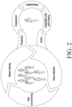
- FIG. 2 is a view illustrating a process for setting a fitness training program per user according to an embodiment of the disclosure.
- the fitness training program since biological reaction differs from person to person, the fitness training program needs to be modified to fit each user to produce an exercise effect.
- the cardiovascular system affects heart rate inertia and slow heart rate changes even with rapid changes in activity, and it is necessary to preset an effective training schedule and consider individual cardiovascular characteristics according to activity.
- the fitness training program for each user may be performed through data pre-processing, model training, and data collection processes.
- exercise data may be collected for each user, the data may be pre-processed, and fitness model training may be performed.
- the user's exercise data may be collected (or recollected) through prediction, explanation, interpretation, integration with prior history, and action processes on the user's exercise after model training.
- the heart rate sensor may include at least one of a photoplethysmogram (PPG) sensor and an electrocardiogram (ECG) sensor.
- PPG photoplethysmogram
- ECG electrocardiogram
- the PPG sensor may be periodically exposed to ambient light saturation due to the user's hand motion during intensive exercise.
- the ECG sensor may generate noise due to a change in the electrode contact area during the user's intensive exercise.
- cardiac output refers to the total amount of blood expelled from the heart and is typically measured in liters per minute.
- Heart rate refers to how often the heart beats and may be measured per minute.
- Stroke volume refers to the amount of blood ejected from the heart at each beat, and the cardiac output may be the product of the heart rate and the stroke volume.
- an increase in cardiac output may be due to an increase in heart rate and stroke volume.
- an increase in cardiac output may be entirely due to an increase in heart rate.
- cardiac output may increase due to an increase in heart rate.
- the heart rate (HR) may be finely measured when the user is calm.
- the wearable device may include at least one of a photoplethysmogram (PPG) sensor, an electrocardiogram (ECG) sensor, and a bioimpedance (BIA) sensor to measure the heart rate.
- PPG photoplethysmogram
- ECG electrocardiogram
- BIOA bioimpedance
- the PPG sensor may be implemented to be included in a smart watch
- the ECG sensor may be implemented to be included in a fitness belt
- the BIA sensor may be implemented to be included in a fitness tracker and a smart ring.
- intensive exercise of the wearable device user may have a negative effect on all heart rate sensors.
- the PPG sensor may expose periodic ambient light saturation due to the user's hand movement
- the ECG sensor may generate noise due to a change in electrode contact area due to the user's body transformation
- the BIA sensor may generate noise due to neural impulses (e.g., mussels neural impulses) caused by the user's movement.
- the electronic device may detect and predict the heart rate (HR) of the user during exercise considering both the direct heart rate signal measured through the heart rate sensor and the user movement detected through the motion sensor.
- a measurement error generated according to the user's movement may be included in the direct heart rate signal measured by the heart rate sensor.
- the electronic device may identify a time duration in which the user moves less based on motion data corresponding to the user's movement and sets the user's movement-heart rate relationship using the heart rate data of the time duration in which the user moves less to thereby enhance the accuracy of heart rate estimation for the user.
- the heart rate data of the time duration in which the user moves less may include fewer measurement errors than the heart rate data in the time duration in which the user moves more.
- the electronic device may set (or correct) the heart rate (HR) trend to be user customized using the relationship between the motion data and the heart rate value when the heart rate is well measured for each user (or heart rate value of good quality).
- the heart rate value when the heart rate is well measured may be measured in a time duration in which the user moves less.
- setting (or correcting) the heart rate (HR) trend to be user-customized may also be expressed as "normalizing the heart rate trend".
- the electronic device may estimate the user's heart rate using the normalized heart rate trend information in the time duration in which the user's heart rate is not well measured due to noise.
- the electronic device may measure the user's activity intensity in a preset time duration considering the user's movement. According to various embodiments, the electronic device may detect and calculate the heart rate (HR) in real-time during intensive exercise by the user wearing the electronic device and may predict a heart rate (HR) pattern for a given activity pattern. According to various embodiments, the electronic device may predict and calculate an activity pattern for a heart rate (HR) pattern required in the future.
- HR heart rate
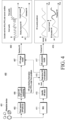
- FIG. 3 is a view 300 illustrating operations of a wearable device according to an embodiment of the disclosure.
- a wearable device 310 may include a first sensor 312, a second sensor 314, a processor 316, and a communication module 318.
- the wearable device 310 may be implemented as the electronic device 101 of FIG. 1 .
- the first sensor 312 may be at least one of a photoplethysmogram (PPG) sensor, an electrocardiogram (ECG) sensor, and a bioimpedance (BIA) sensor and may also be referred to as a vital sign measurement sensor.
- PPG photoplethysmogram
- ECG electrocardiogram
- BIOA bioimpedance
- the second sensor 314 may be at least one of a gyroscope, an accelerometer, a geomagnetic sensor, a radar sensor, and a video camera and may also be referred to as a motion detection sensor (or motion sensor).
- the server 320 may include a communication module 322 and a processor 324.
- the server 320 may be implemented as the server 108 of FIG. 1 .
- the processor 316 implemented in the wearable device 310 may identify a vital sign determined through a first signal obtained through the first sensor 312.
- the vital sign may be any one of a heart rate, a stress value, a respiration rate, and a lactate value.
- the processor 316 implemented in the wearable device 310 may normalize the vital sign determined through the first signal to be user-customized according to the user's activity level determined based on a second signal obtained through the second sensor 314.
- the activity level may be determined based on at least one of the user's activity type, the user's activity intensity, and the user's activity duration.
- the processor 316 implemented in the wearable device 310 may identify the time duration in which the user moves less according to the user's activity level determined based on the second signal obtained through the second sensor 314. According to various embodiments, the processor 316 may compare the user's activity level value with a threshold and, when the activity level value is smaller than the threshold, may determine that the user moves less.
- the processor 316 implemented in the wearable device 310 may set (or correct) the vital sign trend (e.g., heart rate trend) to be user-customized, using the user's movement-vital sign relationship.
- setting (or correcting) the vital sign trend to be customized for each user may also be referred to as "normalizing the vital sign trend.”
- the processor 316 implemented in the wearable device 310 may modify the vital sign (in real-time) by merging the vital sign determined through the first signal and the vital sign according to the normalized vital sign trend. According to various embodiments, the processor 316 implemented in the wearable device 310 may predict the vital sign for the user's future activity pattern based on the modified vital sign. According to various embodiments, the processor 316 implemented in the wearable device 310 may calculate the user's future activity level pattern for the required vital sign pattern.
- the server 320 may transmit/receive information to and from the wearable device 310 through the communication module 322. According to various embodiments, the server 320 may receive, from the wearable device 310, at least one of information regarding the vital sign determined through the first signal obtained through the first sensor 312, information regarding the user's activity level determined through the second signal obtained through the second sensor 314, and information regarding the vital sign modified by merging the vital sign determined through the first signal and the vital sign according to the normalized vital sign trend.
- FIG. 4 is a view illustrating operations of a system for monitoring and predicting a biometric signal according to an embodiment of the disclosure.
- a system 400 for monitoring and predicting a biometric signal may include at least one wearable device 401.
- the at least one wearable device 401 may include a direct sensor (e.g., a PPG sensor or an ECG sensor) 403 and an inertial measurement unit (IMU) 411.
- the direct sensor 403 may measure a biometric signal (e.g., heart rate (HR)) of the user wearing at least one wearable device 401.
- the biometric signal (e.g., heart rate (HR)) measured by the direct sensor 403 may include noise due to the user's movement.
- the IMU 411 may measure the inertia of the at least one wearable device 401 to measure the angle at which the at least one wearable device 401 is tilted.
- the IMU 411 may be configured as at least one of a gyroscope, an accelerometer, and a geomagnetic sensor.
- the direct sensor 403 may correspond to the first sensor 312 of FIG. 3
- the IMU 411 may correspond to the second sensor 314 of FIG. 3 .
- the at least one wearable device 401 may perform user-customized heart rate (HR) normalization in real-time, based on the heart rate (HR) trend identified through the IMU 411 and the monitoring information about the heart rate (HR) measured by the direct sensor 403 under a preset first condition.
- the heart rate may be normalized to be user-customized based on the relationship between the heart rate (HR) measured by the direct sensor 403 under the first condition and the user's movement (or activity level) measured through the IMU 411.
- the heart rate trend according to activity level may differ per user, and the user's heart rate may be estimated or predicted more accurately by normalizing the heart rate according to the activity level per user.
- the at least one wearable device 401 may perform heart rate (HR) merge modeling based on the monitoring information (heart rate information and quality information) about the heart rate (HR) measured by the direct sensor 403 and the information regarding the heart rate (HR) normalized to be customized according to the user's movement data (or activity level) in step 415 (407).
- the heart rate (HR) merge modeling may mean a modeling scheme using information regarding the heart rate (HR) normalized to be customized according to the user's movement data (or activity level) to accurately estimate the heart rate at the time when the quality of the heart rate (HR) measured by the direct sensor 403 is not good.
- the heart rate (HR) merge modeling may mean a scheme of determining the heart rate in real-time by merging the heart rate of good quality, measured by the direct sensor 403, and the heart rate estimated according to the information regarding the normalized heart rate (HR).
- the at least one wearable device 401 may determine the real-time heart rate (HR) based on the result of heart rate (HR) merge modeling.
- the at least one wearable device 401 may determine (or calculate) the real-time heart rate (HR) by the direct sensor 403 under a preset second condition considering the real-time heart rate (HR) determined based on the heart rate (HR) merge modeling result.
- the preset second condition may mean that the direct sensor 403 detects a heart rate (HR) of poor quality (e.g.., when the noise in the heart rate measurement result exceeds a threshold).
- the preset second condition may mean that the quality value of heart rate (HR) measured by the direct sensor 403 is less than the preset threshold.
- the at least one wearable device 401 may perform heart rate (HR) prediction modeling based on the information regarding the normalized heart rate (HR) in operation 417.
- the at least one wearable device 401 may identify the activity level of the user wearing the at least one wearable device 401 through the IMU 411 to perform activity prediction (or activity forecasting) on the user in operation 419.
- the at least one wearable device 401 may predict the future heart rate (HR) based on the user's activity prediction (or activity forecasting) according to the user's activity level in operation 419.
- the at least one wearable device 401 may determine or identify the user's heart rate (HR) with minimized noise by merging the heart rate (HR) information measured by the direct sensor 403 and the user's activity level-based heart rate (HR) trend information. According to various embodiments, the at least one wearable device 401 may correct the heart rate (HR) in real-time even in the case of poor signal quality, predict the heart rate (HR) pattern for a given activity pattern and modify the user's future activity pattern for the required heart rate (HR) pattern.
- FIG. 5 is a view illustrating operations of a wearable device including a biometric sensor and an activity sensor according to an embodiment of the disclosure.
- the wearable device may include a biometric sensor 501 and an activity sensor 503. According to various embodiments, the wearable device may calculate the user's vital sign during the activity of the user wearing the wearable device. According to various embodiments, upon failing to calculate the user's vital sign, the wearable device may store the vital sign and predict the heart rate pattern for a future moment for a known future exercise type.
- the biometric sensor 501 may be the first sensor 312 of FIG. 3 or the direct sensor 403 of FIG. 4 .
- the biometric sensor 501 may include at least one of a photoplethysmogram (PPG) sensor, an electrocardiogram (ECG) sensor, and a bioimpedance (BIA) sensor to measure the heart rate.
- PPG photoplethysmogram
- ECG electrocardiogram
- BIOA bioimpedance
- the activity sensor 503 may be the second sensor 314 of FIG. 3 or the IMU 411 of FIG. 4 .
- the activity sensor 503 means an inertial measurement unit (IMU), and may include at least one of a gyroscope, an accelerometer, and a geomagnetic sensor.
- IMU inertial measurement unit
- the wearable device may identify the quality of the direct biometric signal obtained through the biometric sensor 501 to calculate the user's vital sign in operation 505.
- the user's vital sign may be a heart rate calculated directly from a photoplethysmogram (PPG) signal, a respiration rate calculated directly from a nasal thermistor, or a blood pressure calculated directly from a cuff tonometer.
- PPG photoplethysmogram
- the wearable device may calculate the vital sign from the direct biometric signal in operation 507.
- the wearable device may identify or calculate the trend pattern of the vital sign based on the activity signal obtained from the activity sensor 503 in operation 509.
- the activity signal may be, when the activity intensity is IMU power, the measurement by the IMU sensor, the activity intensity calculated from the video by activity recognition, the measurement by a motion detection laser/radar/lidar sensor, or global positioning system (GPS) positioning value.
- GPS global positioning system
- the wearable device may real-time normalize the trend pattern of the vital sign to be user-customized based on the vital sign obtained from the biometric signal 501 and the trend pattern of the vital sign obtained from the activity sensor 503 in operation 511.
- step 5 when unable to obtain or calculate the vital sign (or when the direct biometric signal is of poor quality or when the quality of the direct biometric signal is a set threshold or less), the wearable device may real-time restore the vital sign based on the vital sign trend pattern normalized to be user-customized in operation 513.
- step 6 the wearable device may predict a future vital sign for a given future activity pattern considering the vital sign restored in step 5 in operation 515.
- step 7 the wearable device may calculate the future activity pattern for the required vital sign pattern considering the vital sign restored in step 5 in operation 517.
- the smart watch may monitor the heart rate of the smart watch user while the user runs, based on the photoplethysmogram (PPG) signal and accelerometer (ACC) signal using machine learning.
- the smart watch may predict the future heart rate pattern for the user's given future activity pattern and calculate the future activity pattern for the required heart rate pattern.
- FIG. 6 is a view illustrating a direct measurement method of a wearable device according to an embodiment of the disclosure.
- At least one wearable device 610 may measure a direct biometric signal using a PPG sensor 620 and monitor the heart rate (HR) and quality of the heart rate (HR) from the measured biometric signal in operation 630.
- the at least one wearable device 610 may measure a direct biometric signal using the PPG sensor 620 in a preset first condition (e.g., when the quality of the biometric signal measured using the PPG sensor 620 is a preset threshold or more or when the quality of the biometric signal measured using the PPG sensor 620 according to a set criterion is determined to be good) and monitor the heart rate (HR) from the measured biometric signal in operation 640.
- a preset first condition e.g., when the quality of the biometric signal measured using the PPG sensor 620 is a preset threshold or more or when the quality of the biometric signal measured using the PPG sensor 620 according to a set criterion is determined to be good
- the at least one wearable device 610 may determine that the quality of the biometric signal measured using the PPG sensor 620 is poor. According to various embodiments, when the heart rate (HR) spectrum is present in the PPG spectrogram (or when the HR pattern is clearly detected in the PPG spectrum), the at least one wearable device 610 may determine that the quality of the biometric signal measured using the PPG sensor 620 is good.
- FIG. 7 is a view illustrating a heart rate (HR) trend calculation method of a wearable device according to an embodiment of the disclosure.
- a wearable GPS speedometer or a treadmill speedometer may exist as a source for monitoring the wearable device user's activity in operation 710.
- the wearable device may monitor the user's activity intensity by an IMU sensor 720 in operation 730.
- the wearable device may perform modeling of the user's cardiovascular system response versus physical activity intensity based on the monitored activity intensity in operation 740.
- the wearable device may identify a heart rate (HR) trend based on the result of modeling the cardiovascular system response versus physical activity intensity in operation 750.
- the wearable device may identify the trend of the user's vital sign (e.g., stress or respiration rate) based on the modeling result of the cardiovascular system response versus physical activity intensity.
- HR heart rate
- the wearable device may identify a correlation between the heart rate (HR) trend identified based on the modeling result and the actual heart rate (HR).
- FIG. 8A is a view illustrating a normalization process of a wearable device according to an embodiment of the disclosure.
- FIG. 8B is a view illustrating a normalizing a heart rate (HR) pattern according to an embodiment of the disclosure.
- HR heart rate
- the wearable device may monitor the heart rate (HR) and the quality of the heart rate (HR) based on the biometric signal measured using the PPG sensor 810 in operation 820. According to various embodiments, the wearable device may identify the heart rate (HR) trend based on the activity intensity (or activity level) measured using the IMU sensor 840 in operation 850.
- the wearable device may perform user-customized heart rate (HR) normalization in real-time, based on the heart rate (HR) trend (860) obtained through the IMU sensor 840 and the heart rate (HR) monitoring information (830) determined based on the biometric signal obtained by the PPG sensor 810 under the preset first condition in operation 870.
- the wearable device may derive normalization coefficients (880) based on the result of heart rate (HR) normalization.
- the wearable device may perform heart rate trend HR trend normalization through the linear transform of Equation 1.
- a is the deformation coefficient
- b is the translational coefficient
- the coefficient for time I may be obtained through minimization of Equation 2.
- Decay [ j ] ⁇ j-i , where ⁇ is the decay rate
- n is the window size for normalization.
- HR PPG is the measured heart rate
- a*HR ACC +b is the normalized heart rate trend.
- the wearable device may normalize the heart rate (HR) pattern by comparing the directly calculated heart rate (HR) with the heart rate (HR) pattern.
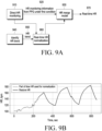
- FIG. 9A is a view illustrating a heart rate (HR) modification process of a wearable device according to an embodiment of the disclosure.
- FIG. 9B is a view illustrating a modified heart rate (HR) according to an embodiment of the disclosure.
- the wearable device may directly perform heart rate (HR) monitoring in operation 910 and provide heart rate (HR) monitoring information from the PPG sensor under the preset first condition to an HR merge model 930 in operation 920.
- the wearable device may identify the heart rate (HR) trend in operation 940 and, based on the heart rate (HR) trend in operation 950, perform real-time heart rate (HR) normalization in a user-customized manner in operation 960.
- the wearable device may provide a real-time heart rate (HR) normalization result to the HR merge model 930.
- the wearable device may derive a real-time heart rate (HR) based on heart rate (HR) monitoring information from the preset PPG sensor under the preset first condition and the result of real-time heart rate (HR) normalization in operation 970.
- the wearable device may estimate the real-time heart rate (HR) based on the real-time heart rate (HR) normalization result in operation 970.
- the HR merge model 930 implemented in the wearable device may modify the heart rate (HR) by merging the normalized heart rate trend (a*HRACC + b) and the heart rate HR PPG measured using the quality metric (mask value) for time i as in Equation 3.
- HR i mask i ⁇ HR PPG i + 1 ⁇ mask i ⁇ a i ⁇ HR ACC i + b i
- the heart rate normalized under the first condition (when the measured signal quality is good) and the heart rate restored under the second condition (when the measured signal quality is poor) may be merged in real-time.
- FIG. 10 is a view illustrating a heart rate (HR) prediction process of a wearable device according to an embodiment of the disclosure.
- At least one wearable device 1010 may real-time normalize the heart rate (HR) based on the user's activity information obtained from an IMU sensor 1030 and the user's biometric signal obtained from a PPG sensor 1020 in operation 1040.
- HR heart rate
- the at least one wearable device 1010 may model the heart rate (HR) prediction based on the real-time heart rate (HR) normalization in operation 1050, predict the heart rate (HR) for the user's future activity exercise pattern based on the modeling result in operation 1060, and calculate the activity for the future heart rate (HR) pattern in operation 1070.
- the at least one wearable device 1010 may identify a heart rate (HR) pattern 1083 predicted during training based on a future activity pattern 1081 during the user's training.
- the at least one wearable device 1010 may identify a future activity exercise pattern 1084 during training based on a future heart rate (HR) pattern 1082 required during the user's training.
- FIG. 11A is a view illustrating an activity defined fitness training according to an embodiment of the disclosure.
- FIG. 11B is a view illustrating a heart rate (HR) defined fitness training according to an embodiment of the disclosure.
- HR heart rate
- the user heart rate (HR) may be predicted in operation 1130.
- the embodiment 1120 of the present disclosure may be any one of the embodiments described with reference to FIGS. 3 to 10 .
- the wearable device may identify the user's activity level according to time during activity-defined fitness training and may perform heart rate (HR) modeling over time.
- the wearable device may recommend the remaining exercise based on the user's predicted heart rate (HR) and fatigue level.
- the wearable device may set a preliminary alarm when the user doing exercise is expected to reach a threshold heart rate (HR) in the future.
- the wearable device may recommend a next exercise to the user based on the required heart rate (HR) and the predicted heart rate (HR).
- the wearable device may recommend a long-term exercise profile in which the heart rate is recovered during exercise based on the required heart rate (HR) and the predicted heart rate (HR).
Landscapes
- Health & Medical Sciences (AREA)
- Life Sciences & Earth Sciences (AREA)
- Engineering & Computer Science (AREA)
- Medical Informatics (AREA)
- Public Health (AREA)
- Biomedical Technology (AREA)
- General Health & Medical Sciences (AREA)
- Pathology (AREA)
- Biophysics (AREA)
- Physics & Mathematics (AREA)
- Veterinary Medicine (AREA)
- Animal Behavior & Ethology (AREA)
- Heart & Thoracic Surgery (AREA)
- Molecular Biology (AREA)
- Surgery (AREA)
- Physiology (AREA)
- Cardiology (AREA)
- Artificial Intelligence (AREA)
- Signal Processing (AREA)
- Psychiatry (AREA)
- Computer Vision & Pattern Recognition (AREA)
- Oral & Maxillofacial Surgery (AREA)
- Dentistry (AREA)
- Epidemiology (AREA)
- Primary Health Care (AREA)
- Pulmonology (AREA)
- Databases & Information Systems (AREA)
- Physical Education & Sports Medicine (AREA)
- Data Mining & Analysis (AREA)
- Nuclear Medicine, Radiotherapy & Molecular Imaging (AREA)
- Radiology & Medical Imaging (AREA)
- Fuzzy Systems (AREA)
- Mathematical Physics (AREA)
- Evolutionary Computation (AREA)
- Business, Economics & Management (AREA)
- General Business, Economics & Management (AREA)
- Measurement Of The Respiration, Hearing Ability, Form, And Blood Characteristics Of Living Organisms (AREA)
- Measuring Pulse, Heart Rate, Blood Pressure Or Blood Flow (AREA)
Applications Claiming Priority (2)
| Application Number | Priority Date | Filing Date | Title |
|---|---|---|---|
| KR1020220005145A KR20230109314A (ko) | 2022-01-13 | 2022-01-13 | 사용자의 생체 사인을 결정하는 전자 장치 및 그 동작 방법 |
| PCT/KR2023/000577 WO2023136628A1 (fr) | 2022-01-13 | 2023-01-12 | Dispositif électronique pour déterminer un signe vital d'un utilisateur et son procédé de fonctionnement |
Publications (2)
| Publication Number | Publication Date |
|---|---|
| EP4424232A1 true EP4424232A1 (fr) | 2024-09-04 |
| EP4424232A4 EP4424232A4 (fr) | 2025-03-19 |
Family
ID=87070450
Family Applications (1)
| Application Number | Title | Priority Date | Filing Date |
|---|---|---|---|
| EP23740471.0A Pending EP4424232A4 (fr) | 2022-01-13 | 2023-01-12 | Dispositif électronique pour déterminer un signe vital d'un utilisateur et son procédé de fonctionnement |
Country Status (3)
| Country | Link |
|---|---|
| US (1) | US20230218201A1 (fr) |
| EP (1) | EP4424232A4 (fr) |
| CN (1) | CN118591341A (fr) |
Family Cites Families (4)
| Publication number | Priority date | Publication date | Assignee | Title |
|---|---|---|---|---|
| CN107529991B (zh) * | 2015-04-16 | 2020-12-18 | 皇家飞利浦有限公司 | 用于检测对象的心脏和/或呼吸疾病的设备、系统和方法 |
| US20180353090A1 (en) * | 2017-06-13 | 2018-12-13 | Huami Inc. | Adaptive Heart Rate Estimation |
| EP4736759A2 (fr) * | 2017-10-17 | 2026-05-06 | Whoop, Inc. | Mesures de qualité de données appliquées pour des mesures physiologiques |
| EP3581093A1 (fr) * | 2018-06-13 | 2019-12-18 | Koninklijke Philips N.V. | Détermination de la fiabilité des signes vitaux chez un sujet surveillé |
-
2023
- 2023-01-12 US US18/153,691 patent/US20230218201A1/en active Pending
- 2023-01-12 EP EP23740471.0A patent/EP4424232A4/fr active Pending
- 2023-01-12 CN CN202380017140.7A patent/CN118591341A/zh active Pending
Also Published As
| Publication number | Publication date |
|---|---|
| EP4424232A4 (fr) | 2025-03-19 |
| CN118591341A (zh) | 2024-09-03 |
| US20230218201A1 (en) | 2023-07-13 |
Similar Documents
| Publication | Publication Date | Title |
|---|---|---|
| US11899845B2 (en) | Electronic device for recognizing gesture and method for operating the same | |
| US12377318B2 (en) | Electronic apparatus and operation method for providing of workout guide thereof | |
| EP3860446B1 (fr) | Dispositif électronique pour obtenir la valeur de la pression artérielle en utilisant l'algorithme de la vitesse de l'onde de pouls et méthode pour obtenir la valeur de la pression artérielle | |
| EP4295759B1 (fr) | Appareil électronique portable pour mesurer la pression artérielle et son procédé de fonctionnement | |
| US20240033575A1 (en) | Wearable electronic device for outputting information on exercise, and control method of wearable electronic device | |
| US20240032828A1 (en) | Biometric information detection method and electronic device for implementing same | |
| US12415125B2 (en) | Method for providing workout data using a plurality of electronic devices and electronic devices therefor | |
| US20230118067A1 (en) | Electronic device and method to measure bioelectrical impedance | |
| EP4424232A1 (fr) | Dispositif électronique pour déterminer un signe vital d'un utilisateur et son procédé de fonctionnement | |
| US12562043B2 (en) | Method for detecting fall of user and electronic device supporting the same | |
| KR20230109314A (ko) | 사용자의 생체 사인을 결정하는 전자 장치 및 그 동작 방법 | |
| US12226224B2 (en) | Method for detecting sleep apnea and electronic device for supporting the same | |
| EP4152720A1 (fr) | Procédé de transmission de données et dispositif électronique le prenant en charge | |
| US20250375159A1 (en) | Wearable device for monitoring body water, electronic device, and operation method therefor | |
| EP4544996A1 (fr) | Dispositif électronique pour mesurer des informations biométriques et son procédé de fonctionnement | |
| US12458279B2 (en) | Method for detecting biometric information and electronic device supporting the same | |
| US20250194956A1 (en) | Wearable device, method and storage medium for providing information on physical activity of user | |
| KR20220017340A (ko) | 제스처를 인식하는 전자 장치 및 그 동작 방법 | |
| US20250255538A1 (en) | Wearable device estimating sweat loss and method for controlling the same | |
| US20250281083A1 (en) | Oxygen saturation measurement guide method and wearable device therefor | |
| US20250186839A1 (en) | System and method for generating workout routine | |
| US20250169705A1 (en) | Electronic device and method for generating data related to heart rate using the same | |
| EP4372521A1 (fr) | Dispositif électronique portable et procédé par lequel un dispositif électronique portable fournit des informations de brossage de dents | |
| EP4732759A1 (fr) | Dispositif habitronique et procédé d'identification d'état de port sur la base de la température, et support d'enregistrement non transitoire lisible par ordinateur | |
| KR20240087483A (ko) | 호흡률 측정 방법 및 전자 장치 |
Legal Events
| Date | Code | Title | Description |
|---|---|---|---|
| STAA | Information on the status of an ep patent application or granted ep patent |
Free format text: STATUS: THE INTERNATIONAL PUBLICATION HAS BEEN MADE |
|
| PUAI | Public reference made under article 153(3) epc to a published international application that has entered the european phase |
Free format text: ORIGINAL CODE: 0009012 |
|
| STAA | Information on the status of an ep patent application or granted ep patent |
Free format text: STATUS: REQUEST FOR EXAMINATION WAS MADE |
|
| 17P | Request for examination filed |
Effective date: 20240529 |
|
| AK | Designated contracting states |
Kind code of ref document: A1 Designated state(s): AL AT BE BG CH CY CZ DE DK EE ES FI FR GB GR HR HU IE IS IT LI LT LU LV MC ME MK MT NL NO PL PT RO RS SE SI SK SM TR |
|
| A4 | Supplementary search report drawn up and despatched |
Effective date: 20250214 |
|
| RIC1 | Information provided on ipc code assigned before grant |
Ipc: G16H 20/30 20180101ALI20250210BHEP Ipc: A61B 5/053 20210101ALI20250210BHEP Ipc: A61B 5/28 20210101ALI20250210BHEP Ipc: A61B 5/00 20060101ALI20250210BHEP Ipc: A61B 5/11 20060101ALI20250210BHEP Ipc: A61B 5/024 20060101ALI20250210BHEP Ipc: A61B 5/0205 20060101AFI20250210BHEP |
|
| DAV | Request for validation of the european patent (deleted) | ||
| DAX | Request for extension of the european patent (deleted) |