EP4424552A2 - Dameuse et procédé de commande de l'alimentation électrique d'une dameuse - Google Patents
Dameuse et procédé de commande de l'alimentation électrique d'une dameuse Download PDFInfo
- Publication number
- EP4424552A2 EP4424552A2 EP24190273.3A EP24190273A EP4424552A2 EP 4424552 A2 EP4424552 A2 EP 4424552A2 EP 24190273 A EP24190273 A EP 24190273A EP 4424552 A2 EP4424552 A2 EP 4424552A2
- Authority
- EP
- European Patent Office
- Prior art keywords
- fuel cell
- power distribution
- accumulator
- distribution unit
- electrical
- Prior art date
- Legal status (The legal status is an assumption and is not a legal conclusion. Google has not performed a legal analysis and makes no representation as to the accuracy of the status listed.)
- Granted
Links
Images

Classifications
-
- B—PERFORMING OPERATIONS; TRANSPORTING
- B60—VEHICLES IN GENERAL
- B60L—PROPULSION OF ELECTRICALLY-PROPELLED VEHICLES; SUPPLYING ELECTRIC POWER FOR AUXILIARY EQUIPMENT OF ELECTRICALLY-PROPELLED VEHICLES; ELECTRODYNAMIC BRAKE SYSTEMS FOR VEHICLES IN GENERAL; MAGNETIC SUSPENSION OR LEVITATION FOR VEHICLES; MONITORING OPERATING VARIABLES OF ELECTRICALLY-PROPELLED VEHICLES; ELECTRIC SAFETY DEVICES FOR ELECTRICALLY-PROPELLED VEHICLES
- B60L50/00—Electric propulsion with power supplied within the vehicle
- B60L50/50—Electric propulsion with power supplied within the vehicle using propulsion power supplied by batteries or fuel cells
- B60L50/75—Electric propulsion with power supplied within the vehicle using propulsion power supplied by batteries or fuel cells using propulsion power supplied by both fuel cells and batteries
-
- B—PERFORMING OPERATIONS; TRANSPORTING
- B60—VEHICLES IN GENERAL
- B60L—PROPULSION OF ELECTRICALLY-PROPELLED VEHICLES; SUPPLYING ELECTRIC POWER FOR AUXILIARY EQUIPMENT OF ELECTRICALLY-PROPELLED VEHICLES; ELECTRODYNAMIC BRAKE SYSTEMS FOR VEHICLES IN GENERAL; MAGNETIC SUSPENSION OR LEVITATION FOR VEHICLES; MONITORING OPERATING VARIABLES OF ELECTRICALLY-PROPELLED VEHICLES; ELECTRIC SAFETY DEVICES FOR ELECTRICALLY-PROPELLED VEHICLES
- B60L1/00—Supplying electric power to auxiliary equipment of vehicles
- B60L1/003—Supplying electric power to auxiliary equipment of vehicles to auxiliary motors, e.g. for pumps, compressors
-
- B—PERFORMING OPERATIONS; TRANSPORTING
- B60—VEHICLES IN GENERAL
- B60L—PROPULSION OF ELECTRICALLY-PROPELLED VEHICLES; SUPPLYING ELECTRIC POWER FOR AUXILIARY EQUIPMENT OF ELECTRICALLY-PROPELLED VEHICLES; ELECTRODYNAMIC BRAKE SYSTEMS FOR VEHICLES IN GENERAL; MAGNETIC SUSPENSION OR LEVITATION FOR VEHICLES; MONITORING OPERATING VARIABLES OF ELECTRICALLY-PROPELLED VEHICLES; ELECTRIC SAFETY DEVICES FOR ELECTRICALLY-PROPELLED VEHICLES
- B60L50/00—Electric propulsion with power supplied within the vehicle
- B60L50/50—Electric propulsion with power supplied within the vehicle using propulsion power supplied by batteries or fuel cells
- B60L50/70—Electric propulsion with power supplied within the vehicle using propulsion power supplied by batteries or fuel cells using power supplied by fuel cells
- B60L50/71—Arrangement of fuel cells within vehicles specially adapted for electric vehicles
-
- B—PERFORMING OPERATIONS; TRANSPORTING
- B60—VEHICLES IN GENERAL
- B60L—PROPULSION OF ELECTRICALLY-PROPELLED VEHICLES; SUPPLYING ELECTRIC POWER FOR AUXILIARY EQUIPMENT OF ELECTRICALLY-PROPELLED VEHICLES; ELECTRODYNAMIC BRAKE SYSTEMS FOR VEHICLES IN GENERAL; MAGNETIC SUSPENSION OR LEVITATION FOR VEHICLES; MONITORING OPERATING VARIABLES OF ELECTRICALLY-PROPELLED VEHICLES; ELECTRIC SAFETY DEVICES FOR ELECTRICALLY-PROPELLED VEHICLES
- B60L50/00—Electric propulsion with power supplied within the vehicle
- B60L50/50—Electric propulsion with power supplied within the vehicle using propulsion power supplied by batteries or fuel cells
- B60L50/70—Electric propulsion with power supplied within the vehicle using propulsion power supplied by batteries or fuel cells using power supplied by fuel cells
- B60L50/72—Constructional details of fuel cells specially adapted for electric vehicles
-
- B—PERFORMING OPERATIONS; TRANSPORTING
- B60—VEHICLES IN GENERAL
- B60L—PROPULSION OF ELECTRICALLY-PROPELLED VEHICLES; SUPPLYING ELECTRIC POWER FOR AUXILIARY EQUIPMENT OF ELECTRICALLY-PROPELLED VEHICLES; ELECTRODYNAMIC BRAKE SYSTEMS FOR VEHICLES IN GENERAL; MAGNETIC SUSPENSION OR LEVITATION FOR VEHICLES; MONITORING OPERATING VARIABLES OF ELECTRICALLY-PROPELLED VEHICLES; ELECTRIC SAFETY DEVICES FOR ELECTRICALLY-PROPELLED VEHICLES
- B60L58/00—Methods or circuit arrangements for monitoring or controlling batteries or fuel cells, specially adapted for electric vehicles
- B60L58/30—Methods or circuit arrangements for monitoring or controlling batteries or fuel cells, specially adapted for electric vehicles for monitoring or controlling fuel cells
-
- B—PERFORMING OPERATIONS; TRANSPORTING
- B60—VEHICLES IN GENERAL
- B60L—PROPULSION OF ELECTRICALLY-PROPELLED VEHICLES; SUPPLYING ELECTRIC POWER FOR AUXILIARY EQUIPMENT OF ELECTRICALLY-PROPELLED VEHICLES; ELECTRODYNAMIC BRAKE SYSTEMS FOR VEHICLES IN GENERAL; MAGNETIC SUSPENSION OR LEVITATION FOR VEHICLES; MONITORING OPERATING VARIABLES OF ELECTRICALLY-PROPELLED VEHICLES; ELECTRIC SAFETY DEVICES FOR ELECTRICALLY-PROPELLED VEHICLES
- B60L58/00—Methods or circuit arrangements for monitoring or controlling batteries or fuel cells, specially adapted for electric vehicles
- B60L58/30—Methods or circuit arrangements for monitoring or controlling batteries or fuel cells, specially adapted for electric vehicles for monitoring or controlling fuel cells
- B60L58/32—Methods or circuit arrangements for monitoring or controlling batteries or fuel cells, specially adapted for electric vehicles for monitoring or controlling fuel cells for controlling the temperature of fuel cells, e.g. by controlling the electric load
-
- B—PERFORMING OPERATIONS; TRANSPORTING
- B60—VEHICLES IN GENERAL
- B60L—PROPULSION OF ELECTRICALLY-PROPELLED VEHICLES; SUPPLYING ELECTRIC POWER FOR AUXILIARY EQUIPMENT OF ELECTRICALLY-PROPELLED VEHICLES; ELECTRODYNAMIC BRAKE SYSTEMS FOR VEHICLES IN GENERAL; MAGNETIC SUSPENSION OR LEVITATION FOR VEHICLES; MONITORING OPERATING VARIABLES OF ELECTRICALLY-PROPELLED VEHICLES; ELECTRIC SAFETY DEVICES FOR ELECTRICALLY-PROPELLED VEHICLES
- B60L58/00—Methods or circuit arrangements for monitoring or controlling batteries or fuel cells, specially adapted for electric vehicles
- B60L58/40—Methods or circuit arrangements for monitoring or controlling batteries or fuel cells, specially adapted for electric vehicles for controlling a combination of batteries and fuel cells
Definitions
- the invention relates to a snow groomer with a drive system for a tracked undercarriage, which comprises an electric drive for each side of the tracked undercarriage, and with an electrical energy source for supplying at least the electric drives.
- the invention also relates to a method for controlling the electrical energy supply of a snow groomer according to the invention.
- a snow groomer with an electric drive for each side of the track is known.
- an electric motor is assigned to each side of the track.
- a rear-side piste processing unit is provided, the milling shaft of which is also driven by an electric motor.
- a battery or a fuel cell system is provided as the power source for these electric drives.
- a hydraulic system can also be operated by means of an electric motor and a gear pump.
- An auxiliary battery with a voltage of 24 V is used to supply additional electrical consumers such as vehicle lighting and the like with power.
- a crawler excavator that has two electric motors, each of which drives a drive chain.
- a fuel cell provides electrical energy.
- a supercapacitor serves as a buffer.
- a power distribution unit distributes the electrical energy from the fuel cell to the drive motors and, if necessary, the supercapacitor.
- An electric motor can be provided to drive a hydraulic pump, with the hydraulic pump then operating the excavator arm with the bucket.
- German utility model specification DE 20 2013 004 087 U1 describes a snow groomer with an electric drive.
- the drive works with a high-voltage system.
- An auxiliary battery with a voltage of 24 V is provided for additional electrical consumers, such as vehicle lighting.
- the fuel cell system has a compressor for supplying air to the fuel cell.
- the fuel cell vehicle has an eddy current brake to enable braking of the fuel cell vehicle when the vehicle battery is fully charged.
- the device has a storage tank for liquefied hydrogen.
- EP 1 182 722 A2 A fuel cell system is known. A cardanic suspension of the fuel cell system is mentioned.
- the invention is intended to improve a snow groomer with an electric drive system and a method for controlling the electrical energy supply of a snow groomer.
- a snow groomer is provided with an electric drive system for a crawler track, which comprises an electric drive for each side of the crawler track, and with an electrical energy source for supplying at least the electric drive, in which the electrical energy source has at least one accumulator, at least one fuel cell and a power distribution unit, wherein the power distribution unit is electrically connected on the one hand to the at least one fuel cell and the accumulator and on the other hand to the electric drive.
- the electrical energy required for the electric drive system can be provided either by the fuel cell, by the accumulator or by the fuel cell and the accumulator together.
- the fuel cell provides the basic electrical power and the accumulator is responsible for the power in the dynamic range.
- the electrical energy then generated by the electric drive can be easily fed into the accumulator. This enables a bidirectional flow of energy, with the exception of the fuel cell.
- the electrical range can be increased considerably and the snow groomer according to the invention can be adjusted much better to current requirements in pure driving operation or in grooming operation.
- the electric drive which comprises an electric drive for each side of the track drive, also serves this purpose. The electrical energy can thus be transferred to the crawler track with lower losses than would be possible with the interposition of a hydrostatic drive, which in turn is powered by an electric motor.
- a piste grooming unit which is arranged at the rear and is driven by means of a first electric drive which is electrically connected to the power distribution unit.
- the piste processing unit is designed as a rear tiller and a drive shaft of the rear tiller is driven by the first electric drive.
- the piste processing unit can also be provided with hydraulic cylinders for raising, lowering and pressing or the like.
- electric servomotors can also be used instead of hydraulic components.
- the electrical energy required for the first electric drive is provided by the power distribution unit, so that here too the at least one fuel cell, the accumulator and/or the fuel cell and the accumulator can be used together to provide the electrical energy.
- a hydraulic system which is driven by means of a second electric drive which is electrically connected to the power distribution unit.
- a hydraulic system is sensible, as hydraulic components, for example for raising and lowering a snow blade and for raising and lowering a piste preparation unit, have been tried and tested for many years and are also suitable for the extreme Environmental conditions under which snow groomers are used.
- the second electric drive which in turn drives a hydraulic pump, is supplied with electrical energy via the power distribution unit.
- the fuel cell alone, the accumulator alone, or the fuel cell and the accumulator together can be used to operate the hydraulic system.
- an electrical low-voltage network with a voltage in the range of 12 V to 48 V is provided, in particular for operating lights, instruments, control devices and the like, wherein the low-voltage network is electrically connected to the power distribution unit.
- a heater for the driver's cab can also be operated via the low-voltage network, whereby within the scope of the invention a heater for the driver's cab can also be operated at a higher voltage and can be supplied with electrical energy directly from the power distribution unit.
- Solar cells are also connected to the low-voltage electrical network if necessary. Snow groomers usually work at night and are usually switched off for several hours during the day. Solar cells can then cause or support the charging of a battery in the low-voltage network.
- the low-voltage electrical network has at least one low-voltage accumulator.
- the power distribution unit is designed as a high-voltage power distribution unit and operates with a voltage in the range between 100 V and 1000 V, in particular 400 V.
- a high-voltage power supply is particularly advantageous when providing high electrical power, such as that required for an electric drive system for a tracked vehicle, as the required cable cross-sections can be reduced, for example.
- the power distribution unit is designed to supply electrical energy from the at least one fuel cell, from the accumulator and/or from a stationary network to the travel drives.
- the power distribution unit can therefore be used to take the required electrical energy or the required electrical power from the at least one fuel cell, from the at least one accumulator and/or from a stationary network.
- the power distribution unit can therefore be used to respond quickly and efficiently to the electrical power that is currently required.
- the fuel cell is used to supply a base load, whereas the dynamic provision of electrical power takes place via the accumulator.
- the required electrical energy can also be supplied via a stationary network, for example when preparing spatially limited snow parks, when preparing steep slopes using winches, or when working on lift tracks, cross-country trails or walking paths using an overhead line connection.
- the power distribution unit is designed to supply electrical energy from the at least one fuel cell, from the accumulator and/or from a stationary network to the first electrical drive for the piste grooming unit, to the second electrical drive for the hydraulic system and/or to the low-voltage network.
- a cable connection can be implemented in winch operation or when working on spatially limited snow parks.
- the power distribution unit can be used to control the supply of electrical energy to the individual electrical consumers by using the fuel cell alone, the accumulator alone, or the fuel cell and the accumulator together. In recuperation mode when electrical energy is fed back into the system, the accumulator can be charged.
- the power distribution unit is designed to supply electrical energy from the at least one fuel cell, from the electric drive systems and/or from a stationary network to the accumulator.
- the battery can be charged using the power distribution unit, even in recuperation mode when electrical energy is generated by the drive systems.
- the power distribution unit is designed to supply electrical energy from the at least one fuel cell and/or from the accumulator to a stationary network.
- the snowcat can serve as an emergency power generator.
- the power distribution unit supplies the electrical energy required for a base load of the drive systems from the at least one fuel cell to the drive systems, and the power distribution unit supplies the electrical energy required for a peak load of the drive systems from the accumulator to the drive systems.
- a mechanically or hydraulically actuated brake is provided for the crawler track.
- an eddy current brake is provided for the chain drive.
- An eddy current brake allows for very sensitive braking.
- the at least one fuel cell is gimbal-mounted on a vehicle frame of the snow groomer.
- Snow groomers are regularly driven in extreme terrain. A gimbal suspension of the fuel cell can then ensure its reliable function.
- a pre-compressor is provided for compressing ambient air, wherein the compressed air can be supplied from the pre-compressor to the fuel cell.
- the fuel cell can be operated with good efficiency and high electrical output even at high altitudes.
- each drive side of the crawler track is provided with a sprocket, wherein an electric motor of the electric travel drive is designed as a wheel hub motor and arranged in the sprocket.
- the at least one fuel cell is operated with hydrogen and at least one hydrogen tank is provided, wherein the hydrogen tank is designed as a pressure reservoir, cryogenic tank or reservoir for chemically bound hydrogen.
- Cylindrical hydrogen tanks are also known as bottle-shaped hydrogen tanks. Such hydrogen tanks have a circular cylindrical base body with hemispherical end pieces. A U-shaped arrangement of several hydrogen tanks, so that they partially surround a cuboid or box-shaped accumulator, saves space. For example, a unit consisting of accumulator and hydrogen tanks can then be provided for easy replacement.
- the object underlying the invention is also achieved by a method for controlling the electrical power supply of a snow groomer according to the invention, in which the provision of the electrical power required by the electric drive units, the first electric drive for the snow grooming unit and/or the second electric drive for the hydraulic system is provided by means of the power distribution unit, wherein the Power distribution unit provides the required electrical power to the drive systems, the first electric drive and/or the second electric drive at least as a function of a level of the required electrical power from the fuel cells alone, from the accumulator alone or from the fuel cells and the accumulator together.
- the electrical power required for a base load is provided by the fuel cell, while the accumulator is used for the electrical power required in addition to the base load at peak loads and in recuperation mode.
- the performance of the fuel cell can be increased or decreased.
- the accumulator can be charged by means of the fuel cell, for example when it is expected that high peak loads will have to be provided by the accumulator or when the charge level of the accumulator falls below a level considered appropriate.
- the schematic representation of the Fig.1 shows the system architecture of the electrical system of a snow groomer according to the invention.
- the electric drive system has a drive unit 12 for the right side of the drive.
- the drive unit 12 has a permanent magnet synchronous machine 14 and a voltage and frequency converter 16 for controlling the permanent magnet synchronous machine.
- the permanent magnet synchronous machine 14 electrical energy can be converted into a movement of a drive chain (not shown) and when the chain is braked, regenerative energy can be generated, which can then be fed back to the overall system via the voltage and frequency converter 16.
- a drive unit 22 is also provided for the travel drive on the left side.
- the drive unit 22 is constructed in the same way as the drive unit 12 and has a permanent magnet synchronous machine 24 and a voltage and frequency converter 26.
- a drive unit 28 is provided for a piste grooming unit, which is usually arranged at the rear of a snow groomer.
- a milling shaft of the piste grooming unit is driven by an electric motor 30 and the drive unit 28 also has a voltage and frequency converter unit 32.
- an electrical energy source 34 which has several fuel cells in a fuel cell stack 36 and several electrical accumulators in a lithium ion accumulator 38.
- the fuel cells of the fuel cell stack 36 operate with hydrogen, which is produced from Fig.1 hydrogen tanks (not shown).
- the accumulator 38 is designed as a lithium-ion accumulator.
- accumulators other than lithium-ion accumulators can also be used.
- the electrical energy source 34 is connected to a high-voltage power distribution unit 40. Electrical energy from the energy source 34 can be supplied to the high-voltage power distribution unit 40 and the high-voltage power distribution unit 40 can supply electrical energy to the electrical energy source 34.
- the high-voltage power distribution unit 40 operates at a voltage of 700 V and the DC-DC converter 42 can be used to adjust the voltage level of the fuel cell stack 36 to the voltage level of the high-voltage power distribution unit 40.
- the accumulator 38 operates at a voltage of 700 V and consists, in a known manner, of an interconnection of several individual accumulators.
- the high-voltage power distribution unit 40 represents the connecting link between the electrical energy source 34 and the electrical drive units 12, 22.
- the high-voltage power distribution unit 40 can be used to supply electrical energy from the energy source 34 to the two drive units 12, 22 and, conversely, electrical energy generated by the drive units 12 can be fed back to the energy source 34, specifically the accumulator 38.
- the high-voltage power distribution unit 40 can control the fuel cell 36 depending on the electrical power required.
- the high-voltage power distribution unit 40 therefore makes electrical energy from the fuel cell stack 36 alone, from the accumulator 38 alone, or from the fuel cell stack 36 and the accumulator 38 together available to the drive units 12, 22.
- the electrical energy required for a base load of the drive units 12, 22, for example the travel drive on level ground is supplied exclusively by the fuel cell stack 36. Peak loads that are required in addition to the base load by the drive units 12, 22 are supplied from the accumulator 38.
- An electric drive 54 is also provided for an air compressor. Ambient air is compressed by means of the electric drive 54 and fed to the fuel cell stack 36. In this way, the fuel cells of the fuel cell stack 36 can be operated with high electrical power even at very high altitudes.
- the electric drive 54 is supplied with electrical energy from the high-voltage power distribution unit 40 via a voltage converter 56.
- the electrical system of the snow groomer according to the invention has a low-voltage network 60, which is provided for supplying the lighting, instruments, fans and the like of the snow groomer.
- the low-voltage network operates with a voltage of 24 V and has two 12 V accumulators.
- the low-voltage network 60 is supplied with electrical energy from the high-voltage power distribution unit 40 via a voltage converter 62.
- a brake chopper 64 is provided.
- the brake chopper 64 is used to convert excess electrical energy into thermal energy. Any excess electrical energy is fed from the high-voltage power distribution unit 40 to the brake chopper 64.
- the electrical energy generated by the drive units 12, 22 cannot be fully used to recharge the battery 38. This may be the case, for example, if the electrical power generated by the generator is simply too high or if the battery 38 is already fully charged. The excess electrical energy must then be dissipated. This is done by converting the electrical energy into thermal energy in the brake chopper 64.
- the brake chopper 64 has an electrical resistor for this purpose, which is switched into the circuit, then heats up and thereby converts electrical energy into thermal energy. This happens when a voltage in the intermediate circuit between the high-voltage power distribution unit 40 and the brake chopper 64 reaches a level that is dangerous for the components of the overall electrical system. As soon as the voltage in the intermediate circuit decreases again and becomes less than the switch-on voltage, an electrical connection to the electrical resistor is interrupted again via suitable switches, for example power transistors. The process repeats itself as soon as the voltage increases again.
- the electrical system shown enables electrical operation of a snow groomer according to the invention to take place in a very efficient manner.
- the fuel cell stack 36 ensures a considerable extension of the range and also a good efficiency in the generation of electrical energy.
- the fuel cell stack 36 and the accumulator 38 can be used either individually or together to provide electrical energy.
- the drive units 12, 22 provided for each side of the track allow a sensitively controllable electrical drive of the track drive with only minimal losses.
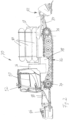
- Fig. 2 shows a side view of a snowcat 70 according to the invention.
- the snowcat 70 is equipped with the Fig.1
- the snowcat 70 has a tracked drive 72, which has drive sides arranged on opposite longitudinal sides.
- Only the left-hand chain of the crawler track can be seen in the direction of travel, whereby the Fig. 2 visible left chain through the drive unit 22 from Fig.1 is powered.
- the chain is guided on each drive side by means of a front tensioning wheel 74 and is driven by means of a rear drive wheel, which is also referred to as a sprocket wheel 76.
- the sprocket wheel 76 is driven by means of the permanently excited synchronous machine 24, see. Fig.1 , driven.
- the design of the permanent magnet synchronous machine 24 as a wheel hub motor in the Turas wheel 76 is possible within the scope of the invention.
- the snowcat 70 has a chassis frame 78. Within this chassis frame 78, which is Fig. 2
- the fuel cell stack 36 is shown partially cut out.
- the other components of the electrical system of the Fig.1 are in Fig. 2 not shown for the sake of clarity.
- the fuel cell stack 36 can be suspended in a gimbal, so that the fuel cells function safely and with high performance even in extreme terrain.
- the fuel cells of the fuel cell stack 36 are operated with hydrogen, which is supplied from hydrogen tanks 80.
- hydrogen tanks 80 In the illustration of the Fig.2 Three cylindrical hydrogen tanks 80 can be seen in which hydrogen is stored under high pressure.
- the hydrogen tanks 80 are arranged in a U-shape around the accumulator 38. This results in a space-saving arrangement of the hydrogen tanks 80 and the accumulator 38.
- the snow groomer 70 further comprises a rear-side slope processing unit 82.
- a milling shaft of the slope processing unit 82 is driven by means of the electric motor 30, see Fig.1 , driven.
- the slope processing unit 82 is pivotally connected to the chassis frame 78 and can be raised and lowered by means of one or more hydraulic cylinders 84 and, if necessary, pivoted and/or pressed by means of further hydraulic cylinders (not shown).
- the hydraulic cylinder 84 is controlled by a Hydraulic system, which is operated by the electric motor 54, see Fig.1 , wherein the electric motor 54 drives, for example, a gear pump.
- the snow groomer 70 is also provided with a clearing blade 86 on the front.
- the clearing blade 86 is hinged to the chassis frame 78 at the front and can be raised, lowered and swivelled by means of several hydraulic cylinders 88.
- the hydraulic cylinders 88 are supplied via the hydraulic system of the snow groomer 70, which is operated by means of the electric motor 54, see Fig.1 , is powered.
- the snowcat 70 has a driver's cab 90 on which, among other things, headlights 92 are mounted. Instruments in the driver's cab and the headlights 92 are part of the low-voltage network 60 of the snowcat 70, see Fig.1 .
- a heater for the driver's cab 90 can either be part of the low-voltage system 60 or directly from the high-voltage power distribution unit 40, see Fig.1 , with a voltage of 700 V. It is also possible to use waste heat generated during operation of the fuel cell stack 36 to heat the driver's cab 90.
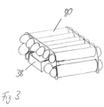
- Fig.3 shows the hydrogen tanks 80 and the accumulator 38 in a view obliquely from above. It can be seen that a total of ten hydrogen tanks 80 are provided, which surround the accumulator in a U-shape. This allows a space-saving arrangement of the accumulator 38 and the hydrogen tanks 80 to be provided.
- the center of gravity of the Fig.3 The arrangement shown is comparatively low, since the accumulator 38 is much heavier than the hydrogen tanks 80.
- the arrangement of the Fig.3 can, as in Fig.2 shown, are arranged on the snowcat 70 so that the hydrogen tanks 80 are parallel to the direction of travel. However, it is easily possible to arrange the Fig.3 also be arranged so that the hydrogen tanks 80 are arranged transversely to the direction of travel.
Landscapes
- Engineering & Computer Science (AREA)
- Life Sciences & Earth Sciences (AREA)
- Sustainable Development (AREA)
- Sustainable Energy (AREA)
- Power Engineering (AREA)
- Transportation (AREA)
- Mechanical Engineering (AREA)
- Fuel Cell (AREA)
Applications Claiming Priority (2)
| Application Number | Priority Date | Filing Date | Title |
|---|---|---|---|
| DE102021202819.5A DE102021202819A1 (de) | 2021-03-23 | 2021-03-23 | Pistenraupe und Verfahren zum Steuern der Stromversorgung einer Pistenraupe |
| EP22159599.4A EP4063184B1 (fr) | 2021-03-23 | 2022-03-02 | Dameuse et procédé de commande de l'alimentation électrique d'une dameuse |
Related Parent Applications (2)
| Application Number | Title | Priority Date | Filing Date |
|---|---|---|---|
| EP22159599.4A Division EP4063184B1 (fr) | 2021-03-23 | 2022-03-02 | Dameuse et procédé de commande de l'alimentation électrique d'une dameuse |
| EP22159599.4A Division-Into EP4063184B1 (fr) | 2021-03-23 | 2022-03-02 | Dameuse et procédé de commande de l'alimentation électrique d'une dameuse |
Publications (3)
| Publication Number | Publication Date |
|---|---|
| EP4424552A2 true EP4424552A2 (fr) | 2024-09-04 |
| EP4424552A3 EP4424552A3 (fr) | 2024-11-20 |
| EP4424552B1 EP4424552B1 (fr) | 2025-11-12 |
Family
ID=80623747
Family Applications (2)
| Application Number | Title | Priority Date | Filing Date |
|---|---|---|---|
| EP22159599.4A Active EP4063184B1 (fr) | 2021-03-23 | 2022-03-02 | Dameuse et procédé de commande de l'alimentation électrique d'une dameuse |
| EP24190273.3A Active EP4424552B1 (fr) | 2021-03-23 | 2022-03-02 | Dameuse et procédé de commande de l'alimentation électrique d'une dameuse |
Family Applications Before (1)
| Application Number | Title | Priority Date | Filing Date |
|---|---|---|---|
| EP22159599.4A Active EP4063184B1 (fr) | 2021-03-23 | 2022-03-02 | Dameuse et procédé de commande de l'alimentation électrique d'une dameuse |
Country Status (2)
| Country | Link |
|---|---|
| EP (2) | EP4063184B1 (fr) |
| DE (1) | DE102021202819A1 (fr) |
Families Citing this family (1)
| Publication number | Priority date | Publication date | Assignee | Title |
|---|---|---|---|---|
| US20250388129A1 (en) * | 2024-06-19 | 2025-12-25 | Prinoth S.P.A. | Fuel cell-powered crawler vehicle and control method thereof |
Citations (9)
| Publication number | Priority date | Publication date | Assignee | Title |
|---|---|---|---|---|
| US5363937A (en) | 1992-10-19 | 1994-11-15 | Lmc Operating Corp. | Battery operated tracked vehicle |
| EP1182722A2 (fr) | 2000-08-22 | 2002-02-27 | DaimlerChrysler AG | Pression équilibrée or regulation de la pression dans un systeme global de piles a combustible |
| KR20110003940A (ko) | 2009-07-07 | 2011-01-13 | 황성조 | 연료전지 굴삭기 |
| DE202013004087U1 (de) | 2012-05-29 | 2013-05-27 | Kässbohrer Geländefahrzeug AG | Pistenraupe |
| EP2684198B1 (fr) | 2011-03-10 | 2014-12-24 | Karlsruher Institut Für Technologie (KIT) | Dispositif de stockage d'hydrogène et d'énergie magnétique, et procédé pour faire fonctionner ledit dispositif |
| EP2726316B1 (fr) | 2011-06-28 | 2016-11-09 | Toyota Jidosha Kabushiki Kaisha | Système de pile à combustible et procédé de commande pour celui-ci |
| DE102018202106A1 (de) | 2018-02-12 | 2019-08-14 | Audi Ag | Energiemanagement eines Brennstoffzellenfahrzeugs |
| EP3608150A1 (fr) | 2018-08-07 | 2020-02-12 | Kässbohrer Geländefahrzeug AG | Engin de damage de pistes doté d'un train de roulement à chenille |
| EP3608151A1 (fr) | 2018-08-07 | 2020-02-12 | Kässbohrer Geländefahrzeug AG | Engin de damage de pistes doté d'un train de roulement à chenille |
Family Cites Families (21)
| Publication number | Priority date | Publication date | Assignee | Title |
|---|---|---|---|---|
| DE19818791A1 (de) | 1998-04-27 | 1999-10-28 | Volkswagen Ag | Scheinwerferbefestigung in einem Kraftfahrzeug |
| JP5007665B2 (ja) | 2007-02-05 | 2012-08-22 | トヨタ自動車株式会社 | 燃料電池システム |
| DE102007024567A1 (de) | 2007-05-25 | 2008-11-27 | Daimler Ag | Hochvolt-Bordnetzarchitektur für ein Brennstoffzellen-Fahrzeug sowie integrierte Leistungselektronik für eine Hochvolt-Bordnetzarchitektur |
| JP5212663B2 (ja) | 2010-10-21 | 2013-06-19 | トヨタ自動車株式会社 | 車両の制駆動力制御装置 |
| JP5456723B2 (ja) | 2011-06-20 | 2014-04-02 | 本田技研工業株式会社 | 燃料電池システム及び該システム搭載車両 |
| JP5474898B2 (ja) | 2011-09-14 | 2014-04-16 | 本田技研工業株式会社 | 燃料電池車両 |
| DE102011083150A1 (de) | 2011-09-21 | 2013-03-21 | Siemens Aktiengesellschaft | Steuerung einer Energie-Rückspeisung von einer Anzahl von Kraftfahrzeug-Akkumulatoren in ein Energienetz |
| DE102012210130A1 (de) | 2012-06-15 | 2013-12-19 | Siemens Aktiengesellschaft | Radantriebseinheit für ein Rad eines elektrisch angetriebenen Fahrzeugs, Fahrzeug und Verfahren zum Betreiben einer Radantriebseinheit eines Fahrzeugs |
| WO2014180489A1 (fr) | 2013-05-08 | 2014-11-13 | Volvo Truck Corporation | Système de propulsion de véhicule comprenant un collecteur d'énergie électrique |
| JP6349384B2 (ja) | 2013-05-15 | 2018-06-27 | ボルボトラックコーポレーション | エネルギー貯蔵システムの充電を制御する方法及び構造 |
| BR112016002592B1 (pt) | 2013-08-06 | 2022-06-14 | Volvo Truck Corporation | Sistema de energia híbrido em um veículo, método para operação de sistema de energia híbrido em um veículo, e veículo compreendendo sistema de energia híbrido |
| US10414283B2 (en) | 2015-07-15 | 2019-09-17 | Honda Motor Co., Ltd. | V2G system and charge/discharge control method based on an estimated power supply-demand state, a minimum trading unit of an amount of power, and a total amount of power secured for selling to a power system |
| DE102015014181A1 (de) | 2015-11-03 | 2016-07-21 | Daimler Ag | Hochvolt-Netz für ein Kraftfahrzeug und Verfahren zum Betreiben eines Hochvolt-Netzes |
| GB2554337B (en) | 2016-05-25 | 2019-10-02 | Jaguar Land Rover Ltd | Apparatus, system and method for braking |
| KR102463694B1 (ko) | 2016-12-09 | 2022-11-07 | 현대자동차주식회사 | 인휠 시스템을 이용한 차량의 주행 제어 방법 |
| US10793157B2 (en) | 2017-05-24 | 2020-10-06 | Toyota Motor Engineering & Manufacturing North America, Inc. | Operating electrified vehicles during traction events |
| DE102017124666B4 (de) | 2017-10-23 | 2023-01-05 | Dr. Ing. H.C. F. Porsche Aktiengesellschaft | Kardanische Lagerung |
| JP7155622B2 (ja) | 2018-06-05 | 2022-10-19 | 日産自動車株式会社 | 電力供給システム |
| DE102019201974A1 (de) | 2019-02-14 | 2020-08-20 | Robert Bosch Gmbh | Elektrische Maschine |
| DE102019104455A1 (de) | 2019-02-21 | 2020-08-27 | Bayerische Motoren Werke Aktiengesellschaft | Vorrichtung und Verfahren zur Befestigung einer Anzeigevorrichtung in einem Fahrzeug |
| IT202000013378A1 (it) | 2020-06-05 | 2021-12-05 | Prinoth Spa | Veicolo cingolato, metodo di controllo e programma per elaboratore elettronico di detto veicolo |
-
2021
- 2021-03-23 DE DE102021202819.5A patent/DE102021202819A1/de active Pending
-
2022
- 2022-03-02 EP EP22159599.4A patent/EP4063184B1/fr active Active
- 2022-03-02 EP EP24190273.3A patent/EP4424552B1/fr active Active
Patent Citations (9)
| Publication number | Priority date | Publication date | Assignee | Title |
|---|---|---|---|---|
| US5363937A (en) | 1992-10-19 | 1994-11-15 | Lmc Operating Corp. | Battery operated tracked vehicle |
| EP1182722A2 (fr) | 2000-08-22 | 2002-02-27 | DaimlerChrysler AG | Pression équilibrée or regulation de la pression dans un systeme global de piles a combustible |
| KR20110003940A (ko) | 2009-07-07 | 2011-01-13 | 황성조 | 연료전지 굴삭기 |
| EP2684198B1 (fr) | 2011-03-10 | 2014-12-24 | Karlsruher Institut Für Technologie (KIT) | Dispositif de stockage d'hydrogène et d'énergie magnétique, et procédé pour faire fonctionner ledit dispositif |
| EP2726316B1 (fr) | 2011-06-28 | 2016-11-09 | Toyota Jidosha Kabushiki Kaisha | Système de pile à combustible et procédé de commande pour celui-ci |
| DE202013004087U1 (de) | 2012-05-29 | 2013-05-27 | Kässbohrer Geländefahrzeug AG | Pistenraupe |
| DE102018202106A1 (de) | 2018-02-12 | 2019-08-14 | Audi Ag | Energiemanagement eines Brennstoffzellenfahrzeugs |
| EP3608150A1 (fr) | 2018-08-07 | 2020-02-12 | Kässbohrer Geländefahrzeug AG | Engin de damage de pistes doté d'un train de roulement à chenille |
| EP3608151A1 (fr) | 2018-08-07 | 2020-02-12 | Kässbohrer Geländefahrzeug AG | Engin de damage de pistes doté d'un train de roulement à chenille |
Also Published As
| Publication number | Publication date |
|---|---|
| EP4424552A3 (fr) | 2024-11-20 |
| EP4063184A1 (fr) | 2022-09-28 |
| DE102021202819A1 (de) | 2022-09-29 |
| EP4424552B1 (fr) | 2025-11-12 |
| EP4063184B1 (fr) | 2025-05-14 |
Similar Documents
| Publication | Publication Date | Title |
|---|---|---|
| EP3049270B1 (fr) | Engin de travail automoteur et procédé de freinage d'un tel engin de travail | |
| WO2022033982A1 (fr) | Pompe à béton montée sur un véhicule | |
| EP3947819A1 (fr) | Machine de compactage de sol avec moteur électrique et procédé de fonctionnement | |
| DE112012005255T5 (de) | Minenlastwagen und regenerative Bremsstrategie dafür | |
| DE102009048828A1 (de) | Hydraulische Vorrichtung und Verfahren zum Betrieb bei einer mobilen Arbeitsmaschine | |
| EP0895495A1 (fr) | Vehicule sur chenilles pour l'entretien de pistes | |
| DE102018210911A1 (de) | Verfahren zum Betreiben eines Antriebssystems für eine Arbeitsmaschine, Antriebssystem und Arbeitsmaschine | |
| WO2013004799A2 (fr) | Véhicule à entraînement électrique pourvu de plusieurs accumulateurs d'énergie électrique | |
| DE102004010988A1 (de) | Hybridantriebssystem für einen Portalhubstapler | |
| DE10244769A1 (de) | Mobile Arbeitsmaschine | |
| DE102021122885A1 (de) | Einsatz- oder Rettungsfahrzeug | |
| EP3990308A1 (fr) | Véhicule présentant une pièce de véhicule électroconductrice pouvant être utilisée comme élément de résistance pour convertir de l'énergie électrique en chaleur | |
| EP4063184B1 (fr) | Dameuse et procédé de commande de l'alimentation électrique d'une dameuse | |
| DE102020210997A1 (de) | Verfahren zum Betreiben eines Antriebsstrangs einer Arbeitsmaschine, Antriebsstrang für eine Arbeitsmaschine und Arbeitsmaschine | |
| DE202007019561U1 (de) | Fahrzeug mit Elektromotor | |
| DE3009772A1 (de) | An kraftfahrzeuge ankuppelbares antriebsaggregat | |
| DE102018213240A1 (de) | Pistenraupe mit einem Kettenlaufwerk | |
| EP4015283B1 (fr) | Unité d'attelage de véhicule doté d'un véhicule tracteur et d'au moins une remorque | |
| DE19831204A1 (de) | Verfahren und Vorrichtung zum Betrieb von elektromotorisch angetriebenen Fahrzeugen | |
| EP3450236A1 (fr) | Véhicule d'intervention ou utilitaire pour une zone d'intervention spatialement limitée | |
| DE102007037690A1 (de) | Flurförderzeug mit einem Fahrmodus und einem Bremsmodus | |
| EP2657058A2 (fr) | Véhicule utilitaire | |
| DE102022203981A1 (de) | Pistenraupe zur Gestaltung und Pflege von Schneegelände | |
| DE202004021457U1 (de) | Hybridantrieb für einen Portalhubstapler | |
| DE29702224U1 (de) | Fahrbarer Geräteträger |
Legal Events
| Date | Code | Title | Description |
|---|---|---|---|
| PUAI | Public reference made under article 153(3) epc to a published international application that has entered the european phase |
Free format text: ORIGINAL CODE: 0009012 |
|
| STAA | Information on the status of an ep patent application or granted ep patent |
Free format text: STATUS: THE APPLICATION HAS BEEN PUBLISHED |
|
| AC | Divisional application: reference to earlier application |
Ref document number: 4063184 Country of ref document: EP Kind code of ref document: P |
|
| AK | Designated contracting states |
Kind code of ref document: A2 Designated state(s): AL AT BE BG CH CY CZ DE DK EE ES FI FR GB GR HR HU IE IS IT LI LT LU LV MC MK MT NL NO PL PT RO RS SE SI SK SM TR |
|
| REG | Reference to a national code |
Ref country code: DE Ref legal event code: R079 Free format text: PREVIOUS MAIN CLASS: B60L0058320000 Ipc: B60L0058400000 Ref country code: DE Ref legal event code: R079 Ref document number: 502022006147 Country of ref document: DE Free format text: PREVIOUS MAIN CLASS: B60L0058320000 Ipc: B60L0058400000 |
|
| PUAL | Search report despatched |
Free format text: ORIGINAL CODE: 0009013 |
|
| AK | Designated contracting states |
Kind code of ref document: A3 Designated state(s): AL AT BE BG CH CY CZ DE DK EE ES FI FR GB GR HR HU IE IS IT LI LT LU LV MC MK MT NL NO PL PT RO RS SE SI SK SM TR |
|
| RIC1 | Information provided on ipc code assigned before grant |
Ipc: B60L 1/00 20060101ALI20241011BHEP Ipc: B60L 58/32 20190101ALI20241011BHEP Ipc: B60L 58/30 20190101ALI20241011BHEP Ipc: B60L 50/72 20190101ALI20241011BHEP Ipc: B60L 50/71 20190101ALI20241011BHEP Ipc: B60L 50/75 20190101ALI20241011BHEP Ipc: B60L 58/40 20190101AFI20241011BHEP |
|
| STAA | Information on the status of an ep patent application or granted ep patent |
Free format text: STATUS: REQUEST FOR EXAMINATION WAS MADE |
|
| 17P | Request for examination filed |
Effective date: 20250507 |
|
| GRAP | Despatch of communication of intention to grant a patent |
Free format text: ORIGINAL CODE: EPIDOSNIGR1 |
|
| STAA | Information on the status of an ep patent application or granted ep patent |
Free format text: STATUS: GRANT OF PATENT IS INTENDED |
|
| RIC1 | Information provided on ipc code assigned before grant |
Ipc: B60L 58/40 20190101AFI20250624BHEP Ipc: B60L 50/75 20190101ALI20250624BHEP Ipc: B60L 50/71 20190101ALI20250624BHEP Ipc: B60L 50/72 20190101ALI20250624BHEP Ipc: B60L 58/30 20190101ALI20250624BHEP Ipc: B60L 58/32 20190101ALI20250624BHEP Ipc: B60L 1/00 20060101ALI20250624BHEP |
|
| INTG | Intention to grant announced |
Effective date: 20250704 |
|
| GRAS | Grant fee paid |
Free format text: ORIGINAL CODE: EPIDOSNIGR3 |
|
| P01 | Opt-out of the competence of the unified patent court (upc) registered |
Free format text: CASE NUMBER: UPC_APP_5409_4424552/2025 Effective date: 20250829 |
|
| GRAA | (expected) grant |
Free format text: ORIGINAL CODE: 0009210 |
|
| STAA | Information on the status of an ep patent application or granted ep patent |
Free format text: STATUS: THE PATENT HAS BEEN GRANTED |
|
| AC | Divisional application: reference to earlier application |
Ref document number: 4063184 Country of ref document: EP Kind code of ref document: P |
|
| AK | Designated contracting states |
Kind code of ref document: B1 Designated state(s): AL AT BE BG CH CY CZ DE DK EE ES FI FR GB GR HR HU IE IS IT LI LT LU LV MC MK MT NL NO PL PT RO RS SE SI SK SM TR |
|
| REG | Reference to a national code |
Ref country code: CH Ref legal event code: F10 Free format text: ST27 STATUS EVENT CODE: U-0-0-F10-F00 (AS PROVIDED BY THE NATIONAL OFFICE) Effective date: 20251112 Ref country code: GB Ref legal event code: FG4D Free format text: NOT ENGLISH Ref country code: CH Ref legal event code: R17 Free format text: ST27 STATUS EVENT CODE: U-0-0-R10-R17 (AS PROVIDED BY THE NATIONAL OFFICE) Effective date: 20251112 |
|
| REG | Reference to a national code |
Ref country code: DE Ref legal event code: R096 Ref document number: 502022006147 Country of ref document: DE |
|
| REG | Reference to a national code |
Ref country code: IE Ref legal event code: FG4D Free format text: LANGUAGE OF EP DOCUMENT: GERMAN |
|
| REG | Reference to a national code |
Ref country code: NL Ref legal event code: MP Effective date: 20251112 |
|
| REG | Reference to a national code |
Ref country code: CH Ref legal event code: U11 Free format text: ST27 STATUS EVENT CODE: U-0-0-U10-U11 (AS PROVIDED BY THE NATIONAL OFFICE) Effective date: 20260401 |
|
| PG25 | Lapsed in a contracting state [announced via postgrant information from national office to epo] |
Ref country code: ES Free format text: LAPSE BECAUSE OF FAILURE TO SUBMIT A TRANSLATION OF THE DESCRIPTION OR TO PAY THE FEE WITHIN THE PRESCRIBED TIME-LIMIT Effective date: 20251112 |
|
| REG | Reference to a national code |
Ref country code: LT Ref legal event code: MG9D |
|
| PG25 | Lapsed in a contracting state [announced via postgrant information from national office to epo] |
Ref country code: NO Free format text: LAPSE BECAUSE OF FAILURE TO SUBMIT A TRANSLATION OF THE DESCRIPTION OR TO PAY THE FEE WITHIN THE PRESCRIBED TIME-LIMIT Effective date: 20260212 |
|
| PGFP | Annual fee paid to national office [announced via postgrant information from national office to epo] |
Ref country code: DE Payment date: 20260324 Year of fee payment: 5 |
|
| PG25 | Lapsed in a contracting state [announced via postgrant information from national office to epo] |
Ref country code: FI Free format text: LAPSE BECAUSE OF FAILURE TO SUBMIT A TRANSLATION OF THE DESCRIPTION OR TO PAY THE FEE WITHIN THE PRESCRIBED TIME-LIMIT Effective date: 20251112 Ref country code: HR Free format text: LAPSE BECAUSE OF FAILURE TO SUBMIT A TRANSLATION OF THE DESCRIPTION OR TO PAY THE FEE WITHIN THE PRESCRIBED TIME-LIMIT Effective date: 20251112 |
|
| PGFP | Annual fee paid to national office [announced via postgrant information from national office to epo] |
Ref country code: AT Payment date: 20260301 Year of fee payment: 5 |
|
| PG25 | Lapsed in a contracting state [announced via postgrant information from national office to epo] |
Ref country code: NL Free format text: LAPSE BECAUSE OF FAILURE TO SUBMIT A TRANSLATION OF THE DESCRIPTION OR TO PAY THE FEE WITHIN THE PRESCRIBED TIME-LIMIT Effective date: 20251112 |
|
| PG25 | Lapsed in a contracting state [announced via postgrant information from national office to epo] |
Ref country code: RS Free format text: LAPSE BECAUSE OF FAILURE TO SUBMIT A TRANSLATION OF THE DESCRIPTION OR TO PAY THE FEE WITHIN THE PRESCRIBED TIME-LIMIT Effective date: 20260212 |
|
| PG25 | Lapsed in a contracting state [announced via postgrant information from national office to epo] |
Ref country code: IS Free format text: LAPSE BECAUSE OF FAILURE TO SUBMIT A TRANSLATION OF THE DESCRIPTION OR TO PAY THE FEE WITHIN THE PRESCRIBED TIME-LIMIT Effective date: 20260312 |
|
| PGFP | Annual fee paid to national office [announced via postgrant information from national office to epo] |
Ref country code: FR Payment date: 20260325 Year of fee payment: 5 |
|
| PG25 | Lapsed in a contracting state [announced via postgrant information from national office to epo] |
Ref country code: PT Free format text: LAPSE BECAUSE OF FAILURE TO SUBMIT A TRANSLATION OF THE DESCRIPTION OR TO PAY THE FEE WITHIN THE PRESCRIBED TIME-LIMIT Effective date: 20260312 |
|
| PG25 | Lapsed in a contracting state [announced via postgrant information from national office to epo] |
Ref country code: PL Free format text: LAPSE BECAUSE OF FAILURE TO SUBMIT A TRANSLATION OF THE DESCRIPTION OR TO PAY THE FEE WITHIN THE PRESCRIBED TIME-LIMIT Effective date: 20251112 |
|
| PG25 | Lapsed in a contracting state [announced via postgrant information from national office to epo] |
Ref country code: LV Free format text: LAPSE BECAUSE OF FAILURE TO SUBMIT A TRANSLATION OF THE DESCRIPTION OR TO PAY THE FEE WITHIN THE PRESCRIBED TIME-LIMIT Effective date: 20251112 |