EP4424561A1 - Befestigungsvorrichtung für ein wischerblatt - Google Patents
Befestigungsvorrichtung für ein wischerblatt Download PDFInfo
- Publication number
- EP4424561A1 EP4424561A1 EP23159206.4A EP23159206A EP4424561A1 EP 4424561 A1 EP4424561 A1 EP 4424561A1 EP 23159206 A EP23159206 A EP 23159206A EP 4424561 A1 EP4424561 A1 EP 4424561A1
- Authority
- EP
- European Patent Office
- Prior art keywords
- attachment device
- wiper
- receiving area
- plane
- lower plane
- Prior art date
- Legal status (The legal status is an assumption and is not a legal conclusion. Google has not performed a legal analysis and makes no representation as to the accuracy of the status listed.)
- Pending
Links
Images

Classifications
-
- B—PERFORMING OPERATIONS; TRANSPORTING
- B60—VEHICLES IN GENERAL
- B60S—SERVICING, CLEANING, REPAIRING, SUPPORTING, LIFTING, OR MANOEUVRING OF VEHICLES, NOT OTHERWISE PROVIDED FOR
- B60S1/00—Cleaning of vehicles
- B60S1/02—Cleaning windscreens, windows or optical devices
- B60S1/04—Wipers or the like, e.g. scrapers
- B60S1/32—Wipers or the like, e.g. scrapers characterised by constructional features of wiper blade arms or blades
- B60S1/38—Wiper blades
- B60S1/3848—Flat-type wiper blade, i.e. without harness
- B60S1/3874—Flat-type wiper blade, i.e. without harness with a reinforcing vertebra
- B60S1/3875—Flat-type wiper blade, i.e. without harness with a reinforcing vertebra rectangular section
-
- B—PERFORMING OPERATIONS; TRANSPORTING
- B60—VEHICLES IN GENERAL
- B60S—SERVICING, CLEANING, REPAIRING, SUPPORTING, LIFTING, OR MANOEUVRING OF VEHICLES, NOT OTHERWISE PROVIDED FOR
- B60S1/00—Cleaning of vehicles
- B60S1/02—Cleaning windscreens, windows or optical devices
- B60S1/04—Wipers or the like, e.g. scrapers
- B60S1/32—Wipers or the like, e.g. scrapers characterised by constructional features of wiper blade arms or blades
- B60S1/38—Wiper blades
-
- B—PERFORMING OPERATIONS; TRANSPORTING
- B60—VEHICLES IN GENERAL
- B60S—SERVICING, CLEANING, REPAIRING, SUPPORTING, LIFTING, OR MANOEUVRING OF VEHICLES, NOT OTHERWISE PROVIDED FOR
- B60S1/00—Cleaning of vehicles
- B60S1/02—Cleaning windscreens, windows or optical devices
- B60S1/04—Wipers or the like, e.g. scrapers
- B60S1/32—Wipers or the like, e.g. scrapers characterised by constructional features of wiper blade arms or blades
- B60S1/38—Wiper blades
- B60S1/3806—Means, or measures taken, for influencing the aerodynamic quality of the wiper blades
- B60S1/381—Spoilers mounted on the squeegee or on the vertebra
-
- B—PERFORMING OPERATIONS; TRANSPORTING
- B60—VEHICLES IN GENERAL
- B60S—SERVICING, CLEANING, REPAIRING, SUPPORTING, LIFTING, OR MANOEUVRING OF VEHICLES, NOT OTHERWISE PROVIDED FOR
- B60S1/00—Cleaning of vehicles
- B60S1/02—Cleaning windscreens, windows or optical devices
- B60S1/04—Wipers or the like, e.g. scrapers
- B60S1/32—Wipers or the like, e.g. scrapers characterised by constructional features of wiper blade arms or blades
- B60S1/38—Wiper blades
- B60S1/3848—Flat-type wiper blade, i.e. without harness
-
- B—PERFORMING OPERATIONS; TRANSPORTING
- B60—VEHICLES IN GENERAL
- B60S—SERVICING, CLEANING, REPAIRING, SUPPORTING, LIFTING, OR MANOEUVRING OF VEHICLES, NOT OTHERWISE PROVIDED FOR
- B60S1/00—Cleaning of vehicles
- B60S1/02—Cleaning windscreens, windows or optical devices
- B60S1/04—Wipers or the like, e.g. scrapers
- B60S1/32—Wipers or the like, e.g. scrapers characterised by constructional features of wiper blade arms or blades
- B60S1/38—Wiper blades
- B60S1/3848—Flat-type wiper blade, i.e. without harness
- B60S1/3886—End caps
- B60S1/3894—End caps having a particular shape
-
- B—PERFORMING OPERATIONS; TRANSPORTING
- B60—VEHICLES IN GENERAL
- B60S—SERVICING, CLEANING, REPAIRING, SUPPORTING, LIFTING, OR MANOEUVRING OF VEHICLES, NOT OTHERWISE PROVIDED FOR
- B60S1/00—Cleaning of vehicles
- B60S1/02—Cleaning windscreens, windows or optical devices
- B60S1/04—Wipers or the like, e.g. scrapers
- B60S1/32—Wipers or the like, e.g. scrapers characterised by constructional features of wiper blade arms or blades
- B60S1/38—Wiper blades
- B60S2001/3827—Wiper blades characterised by the squeegee or blade rubber or wiping element
- B60S2001/3836—Wiper blades characterised by the squeegee or blade rubber or wiping element characterised by cross-sectional shape
- B60S2001/3837—Wiper blades characterised by the squeegee or blade rubber or wiping element characterised by cross-sectional shape with more than one wiping edge or lip
Definitions
- the field of the present invention is that of wipers used on motor vehicles.
- the invention relates particularly to an attachment clip mounted on a wiper.
- the invention also relates to an assemble comprising a wiper and at least one said attachment clip.
- wiper systems for motor vehicles include at least one drive arm and a wiper blade which includes a squeegee blade intended to be brought to bear against a glass surface of the motor vehicle.
- the drive arm is driven in a back-and-forth angular movement against the glass surface of the motor vehicle, during which it drives the wiper blade and its squeegee blade so that it rubs the glass surface and thus removes water, dirt and dust that may impede the motor vehicle driver's view of his surroundings.
- the wiper blade is attached to the drive arm by a connection assembly that comprises a connector integral with the wiper blade and an adapter configured to cooperate with the wiper blade and with an end portion of the drive arm.
- This connection assembly is configured, on the one hand, to allow the reciprocating movements of the wiper blade against the glass surface in question, and, on the other hand, to guarantee an effective flattening of the wiper blade against the glass surface in order to achieve an effective wiping and/or cleaning.
- the wiper blade comprises generally a longitudinal support and a squeegee blade intended to be pressed against the window, the squeegee blade being maintained on the longitudinal support by an attachment device.
- the attachment device is configured so as to be locked on the longitudinal support, and consequently so as to avoid lateral movement between the longitudinal support and the squeegee blade.
- a disadvantage of known automotive systems is that when the glass surface is highly curved, for example on the sides of a windshield, the attachment device may scratch the glass in certain arm positions.
- the invention proposes an attachment device for a wiper blade that is able to avoid scratches on the glass surface during wiping.
- the invention proposes an attachment device for a vehicle window wiper, the attachment device comprising a lower face extending in a lower plane, the attachment device comprising a first part made of a first material, and a second part made of a second material, the second material being more flexible than the first material, the second part being at least in contact with said lower plane.
- the second part of the attachment device is made of a more flexible material than the first part of the attachment device that prevents the attachment device, and more particularly the first part from scratching the window.
- the second part is configured to come between the window and the first part.
- the second part is made of an elastic plastic material, for example ethylene propylene diene monomer (EPDM) Rubber.
- EPDM ethylene propylene diene monomer
- the first part is made of a rigid plastic material, for example acrylonitrile butadiene styrene (ABS).
- ABS acrylonitrile butadiene styrene
- the vehicle window wiper comprises at least one longitudinal support and a squeegee blade intended to be pressed against the window, the second part of the attachment device being made of the same material as a squeegee blade.
- the second part is made of a material which is different from the squeegee blade material.
- the lower face of the attachment device comprises a slot configured to retain the squeegee blade.
- the attachment device on each side of the slot, comprises a notch arranged to tackle the squeegee blade against the longitudinal support.
- the first part is made of a single piece.
- the second part is made of a single piece.
- the second part extends at least partially along the lower plane of which the lower face of the attachment device extends.
- the second part extends totally along the lower plane of which the lower face of the attachment device extends.
- the second part comprises at least a protrusion that protrudes beyond said lower plane in a direction intersecting with said lower plane.
- the second part comprises at least a protrusion that protrudes beyond said lower plane in a direction opposite to said lower plane.
- the protrusion comprises a lip configured to protrude in a direction intersecting with said lower plane.
- the protrusion comprises a lip configured to protrude in a direction opposite to the lower plane.
- the lip is linked to the connecting area by a neck.
- the protrusion has a "pine tree” shape.
- pine tree shape
- the protrusion comprises a lip presenting a triangular shape similar to a squeegee blade, said lip being connected to the connection area by the neck having a thickness lower than the connection area thickness and / or the lip thickness.
- the neck between the connecting area and the lip is flexible.
- the dimensions of the neck are chosen to make it robust and flexible.
- the neck prevents the attachment device to be broken and ensure the second part, more specifically the lip of the second part, to follow the shape of the window against which it is pressed.
- the protrusion has a polygonal or round shape, or a combination of flat and curved surfaces.
- the second part is configured to fit at least partially into the first part.
- the second part is at least partially housed in the first part.
- the first part comprises a receiving area configured to receive a connecting area of the second part, said receiving area and said connecting area being complementary to each other.
- the receiving area comprises a hollow arranged to receive the connecting area of the second part.
- the receiving area of the first part has a shape arranged to maintain the connecting area of the second part in said receiving area.
- the receiving area of the first part comprises at least one holding element, said holding element being arranged to retain the connecting area of the second part in said receiving area.
- At least one holding element comprises a flange, the connecting area of the second part having a shape fitting said flange, the connecting area of the second part being arranged to be retained by said flange.
- At least one holding element comprises a pin, the connecting area of the second part having a shape fitting said pin, the connecting area of the second part being arranged to be retained by said pin.
- the first part is at least partially adjacent to the second part.
- the first part comprises a protuberance, said protuberance comprising the receiving area.
- the attachment device comprises an upper face opposite to the lower face, said upper face extending along an upper plane, the protuberance protruding beyond said upper plane in a direction intersecting with said upper plane.
- the second part comprises at least a border arranged to fit the protuberance of the first part.
- the border is pressed against the protuberance, more particularly against a lower face of the protuberance.
- the lower face is inclined compared to the lower or the upper plane.
- the lower face of the protuberance has a different direction compared to the upper or lower plane.
- the neck is comprised between, the border and the protrusion.
- the first part is configured to be overmolded on the second part.
- the second part is arranged to be mechanically maintained in the first part by the at least one holding element.
- the connecting area of the second part is arranged to be maintained in the receiving rea of the first part by shape complementarity.
- the connecting area of the second part is arranged to be maintained in the receiving rea of the first part by at least one of the holding elements.
- the second part is arranged to be fixed to the first part by at least one fastening means such as glue, clips or welding.
- the second part comprises a hollow.
- the second part is filled with the second material.
- the attachment device comprises a rear longitudinal face configured to be pressed against a window and a front longitudinal face opposite to said rear longitudinal face, said rear and front longitudinal faces extending parallelly to a longitudinal axis.
- the rear longitudinal face is at least partially adjacent to the connecting area of the second part.
- the second part extends all along the rear longitudinal face.
- the rear longitudinal face is part of the second part.
- the rear longitudinal face is made of the first material.
- the first part made of the first material comprises an insertion slot, said insertion slot being at the intersection of the rear longitudinal face and the lower face of the protuberance, said slot being configured to be crossed by the protrusion.
- the second part extends all along the front longitudinal face.
- the front longitudinal face is part of the second part.
- the front longitudinal face is made of the first material.
- the protrusion is intended to be pressed against a window.
- the first part is obtained by extrusion.
- the second part is obtained by extrusion.
- the attachment device comprises at least one retaining element arranged to retain the longitudinal support of the wiper blade.
- the first part comprises said retaining element.
- the retaining elements are for example pins or tips arranged to retain the longitudinal support. This prevents the longitudinal support of the wiper blade from slipping.
- the purpose of the invention is also to propose an assembly comprising:
- the assembly comprises at least one end fitting arranged to be mounted at least one extremity of the wiper.
- the attachment device is arranged to fit the shape of the end fitting.
- the attachment device is arranged to be adjacent to the end fitting.
- the denominations longitudinal or lateral, top, bottom, front, rear refer to the orientation of the wiper or of the attachment device according to the invention.
- the longitudinal direction corresponds to the axis of extension of the blade.
- the lateral direction corresponds to a direction perpendicular to the longitudinal direction and parallel to a windscreen surface upon which the windscreen wiper blade is placed.
- the vertical direction corresponds to a direction perpendicular to the longitudinal direction and normal to said windscreen surface.
- the denominations "upper” and “lower” are relative to said vertical direction.
- the denominations "rear” and "front” are relative to the general orientation of the vehicle on which the blade is mounted, in the same way.
- FIG. 1 shows a perspective view of an attachment device 1 according to the prior art.
- Such an attachment device 1 has a function of mechanically holding the components of a wiper, for example for preventing lateral movements of said components.
- the attachment device 1 has an outside wall 2 complementary to the wiper. Inside an internal volume 3 delimited by the outside wall 2, the attachment device 1 comprises a slot 5, the function of which is to mechanically retain a heel of the squeegee blade of the wiper. Such a slot 5 is formed in the lower face 6 of the attachment device 1. This slot 5 is open towards the outside, this opening being delimited by two hooks notches 7 which extend longitudinally along the attachment device 1.
- the attachment device 1 also comprises a housing arranged to form a volume 8 complementary to the longitudinal support.
- the attachment device 1 of Figure 1 is made of one or more rigid materials.
- an assembly 100 can be seen.
- a wiper 100 is used to wipe a window of a vehicle and to move the water present on this window out of a driver's field of view.
- the assemble 100 is made up of at least one longitudinal support 116, a squeegee blade 117 at least one, or even two, end fittings 118 that are installed on each end part of the longitudinal support 116, and at least one, here four attachment devices 101 are installed on an intermediate section of the wiper.
- the longitudinal support 116 is advantageously flexible.
- the longitudinal support 116 may take the form of a single flat and elastic metal strip.
- the longitudinal support 116 may be formed by two elastic metal strips that are each inserted into a slot formed on either side of the squeegee blade 117.
- the longitudinal support is arranged to retain the squeegee blade.
- such a metal strip in the rest state, is curved in a plane perpendicular to a longitudinal direction of the strip.
- the function of such a metal strip is to distribute along the squeegee blade 117 the bearing forces that are applied by a wiper arm at a connection means 119 attached to the longitudinal support 116 at the center, longitudinally, of the wiper 100.
- connection means 119 is intended to connect the wiper to said wiper arm for driving this wiper in rotation. It may also be one or more air deflectors which are attached to the longitudinal support 116 and the function of which is to convert the air flow passing over the wiper into a bearing force which presses the blade 117 against the window.
- the wiper 100 also comprises two attachment devices 100, here four attachment devices of identical form, as described below with reference to Figures 3 to 5 .
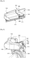
- Figures 3 , 4 and 5 show perspective views of the attachment device 101 according to a first embodiment of the invention.
- the attachment device 101 differs from the attachment device 1 of Fig. 1 in that it comprises a first part 105 made of a rigid plastic material, for example acrylonitrile butadiene styrene (ABS); and a second part 106 made of a more flexible material, for example ethylene propylene diene monomer (EPDM) rubber.
- the attachment device 101 comprises a lower face 107, said lower face 107 extending in a lower plane P and said lower face 107 being provided with a slot 108 open towards the outside.
- the slot 108 is configured to mechanically retain a heel of the squeegee blade of a wiper.
- the second part 106 is made of a material with elastic properties, eliminating the risk of scratching the glass while ensuring effective wiping.
- the second part 106 comprises a protrusion 111, which is here a lip, which protrudes beyond the lower plane P in a direction that intersects with the lower plane P.
- the second part 106 is configured to at least partially make contact with a window 200 ( figure 5 ) to be wiped at certain wiping positions.
- the second part 106 being in contact with the lower plane P on which the lower face 107 of the attachment device 101 extends, the attachment device 101 does not scratch the window during wiping.
- the second part 106 allows to protect the window 200 from the first part 105 of the attachment device which is made of a more rigid material than the second part 106.
- the first part 105 comprises a receiving area 113 configured to receive a connecting area 109 of the second part 106.
- the receiving area 113 of the first part 105 and the connecting area 109 of the second part 106 are complementary to each other.
- the receiving area 113 of the first part 105 is located in a protuberance 120 of the attachment device.
- This protuberance120 extends beyond an upper plan P1 which is parallel to the lower plane P and on which an upper face 121 extends.
- Such a protuberance 120 allows to make easier the mounting of the attachment device 101.
- the attachment device 101 comprises a front longitudinal face 114 which is parallel to a longitudinal axis L and a rear longitudinal face 112, said rear longitudinal face 112 being adjacent to the connecting area 109 of the second part 106.
- the protrusion 111 of the second part 106 extends beyond the lower plane P on which the lower face 107 is extending all along the rear longitudinal face 112.
- the receiving area 109 of the first part 105 and the connecting area 113 of the second part 106 have complementary shapes.
- the shapes of the connecting area 113 and the receiving area 109 comprise at least an angle 115.
- the second part 106 can be overmolded on the first part 105.
- the second part 106 is mechanically retained by the first part 105.
- the receiving area 113 comprises holder elements such as pins 123 and flanges 122 arranged to maintain the connecting area 109 of the second part 106 in the receiving area 113. Hence, the second part is firmly retained in the receiving area 113 of the first part 105.
- first 105 and the second 106 parts could be fixed with at least a clip or glue.
- the second part 106 comprises the connecting area 109, a neck 124, two borders 125 arranged to be pressed against the lower face of the protuberance, and the protrusion 111 arranged to be pressed against a window.
- the neck is arranged between the connecting area 109 and the protrusion 111, more precisely between the borders 125 and the protrusion 111.
- the protrusion 111 has here an "arrow" or "pine tree” shape.
- the second part 106 is configured to make contact with a glass surface, such as a window or a windscreen, at certain wiping positions of a window wiper, and to come between the first part 105 which is made of a rigid material and said window. In consequence, scratches that might otherwise be made by the first part 105 rubbing against the window are avoided.
- a glass surface such as a window or a windscreen
Landscapes
- Engineering & Computer Science (AREA)
- Mechanical Engineering (AREA)
- Physics & Mathematics (AREA)
- Fluid Mechanics (AREA)
- Quality & Reliability (AREA)
- Seal Device For Vehicle (AREA)
Priority Applications (3)
| Application Number | Priority Date | Filing Date | Title |
|---|---|---|---|
| EP23159206.4A EP4424561A1 (de) | 2023-02-28 | 2023-02-28 | Befestigungsvorrichtung für ein wischerblatt |
| CN202480014980.2A CN120769816A (zh) | 2023-02-28 | 2024-02-16 | 用于雨刮片的附接装置 |
| PCT/EP2024/053982 WO2024179857A1 (en) | 2023-02-28 | 2024-02-16 | Attachment device for a wiper blade |
Applications Claiming Priority (1)
| Application Number | Priority Date | Filing Date | Title |
|---|---|---|---|
| EP23159206.4A EP4424561A1 (de) | 2023-02-28 | 2023-02-28 | Befestigungsvorrichtung für ein wischerblatt |
Publications (1)
| Publication Number | Publication Date |
|---|---|
| EP4424561A1 true EP4424561A1 (de) | 2024-09-04 |
Family
ID=85410370
Family Applications (1)
| Application Number | Title | Priority Date | Filing Date |
|---|---|---|---|
| EP23159206.4A Pending EP4424561A1 (de) | 2023-02-28 | 2023-02-28 | Befestigungsvorrichtung für ein wischerblatt |
Country Status (3)
| Country | Link |
|---|---|
| EP (1) | EP4424561A1 (de) |
| CN (1) | CN120769816A (de) |
| WO (1) | WO2024179857A1 (de) |
Citations (4)
| Publication number | Priority date | Publication date | Assignee | Title |
|---|---|---|---|---|
| US2700785A (en) * | 1952-04-15 | 1955-02-01 | Trico Products Corp | Windshield wiper blade |
| US4317251A (en) * | 1979-08-17 | 1982-03-02 | Priesemuth W | Windshield wiper |
| US20130257107A1 (en) * | 2010-11-05 | 2013-10-03 | Daimler Ag | Wiper Blade for a Window Wiper of a Motor Vehicle and Window Arrangement for a Motor Vehicle |
| WO2020136079A1 (de) * | 2018-12-27 | 2020-07-02 | Robert Bosch Gmbh | Wischblattvorrichtung |
-
2023
- 2023-02-28 EP EP23159206.4A patent/EP4424561A1/de active Pending
-
2024
- 2024-02-16 CN CN202480014980.2A patent/CN120769816A/zh active Pending
- 2024-02-16 WO PCT/EP2024/053982 patent/WO2024179857A1/en not_active Ceased
Patent Citations (4)
| Publication number | Priority date | Publication date | Assignee | Title |
|---|---|---|---|---|
| US2700785A (en) * | 1952-04-15 | 1955-02-01 | Trico Products Corp | Windshield wiper blade |
| US4317251A (en) * | 1979-08-17 | 1982-03-02 | Priesemuth W | Windshield wiper |
| US20130257107A1 (en) * | 2010-11-05 | 2013-10-03 | Daimler Ag | Wiper Blade for a Window Wiper of a Motor Vehicle and Window Arrangement for a Motor Vehicle |
| WO2020136079A1 (de) * | 2018-12-27 | 2020-07-02 | Robert Bosch Gmbh | Wischblattvorrichtung |
Also Published As
| Publication number | Publication date |
|---|---|
| WO2024179857A1 (en) | 2024-09-06 |
| CN120769816A (zh) | 2025-10-10 |
Similar Documents
| Publication | Publication Date | Title |
|---|---|---|
| CN1174886C (zh) | 机动车玻璃刮水装置 | |
| US8479350B2 (en) | Automobile wiper-blade | |
| US6295690B1 (en) | Wiper blade for cleaning automobile windscreens | |
| CN102365193B (zh) | 风挡刮雨器装置 | |
| US8701241B2 (en) | Flat wiper blade with spoiler | |
| CN105452069B (zh) | 刮水片以及刮水器 | |
| JP2001500090A (ja) | 自動車のウインドシールドガラスに用いられるワイパ装置 | |
| CN1635964A (zh) | 用于尤其是汽车玻璃的刮水板 | |
| CN1671581A (zh) | 雨刮片 | |
| CN1989032B (zh) | 刮水器臂的连接装置 | |
| US7523523B2 (en) | Windshield wiper with scraper | |
| KR100920169B1 (ko) | 차량용 범용 와이퍼 장치 | |
| EP4424561A1 (de) | Befestigungsvorrichtung für ein wischerblatt | |
| EP4424562A1 (de) | Endstück für ein wischerblatt | |
| US20190248339A1 (en) | Adapter making up a wiper system | |
| JP2019051852A (ja) | ワイパブレード | |
| CN118414272A (zh) | 用于机动车辆的端盖和挡风玻璃雨刮器 | |
| US20250026313A1 (en) | Adapter for a wiping system | |
| KR102461203B1 (ko) | 와이퍼 장치 | |
| CN114945494B (en) | Wiper system for motor vehicle | |
| KR200445232Y1 (ko) | 스포일러 부재 및 이를 구비한 와이퍼 블레이드 | |
| JP2005059630A (ja) | ワイパー装置用取付具及びワイパー装置 | |
| US10246057B2 (en) | Adaptor for connecting a windscreen wiper unit to a driving arm | |
| US11628808B1 (en) | Wiper arm head dual knuckle | |
| US20250360893A1 (en) | Wiper-blade including textured surface |
Legal Events
| Date | Code | Title | Description |
|---|---|---|---|
| PUAI | Public reference made under article 153(3) epc to a published international application that has entered the european phase |
Free format text: ORIGINAL CODE: 0009012 |
|
| STAA | Information on the status of an ep patent application or granted ep patent |
Free format text: STATUS: THE APPLICATION HAS BEEN PUBLISHED |
|
| AK | Designated contracting states |
Kind code of ref document: A1 Designated state(s): AL AT BE BG CH CY CZ DE DK EE ES FI FR GB GR HR HU IE IS IT LI LT LU LV MC ME MK MT NL NO PL PT RO RS SE SI SK SM TR |
|
| STAA | Information on the status of an ep patent application or granted ep patent |
Free format text: STATUS: REQUEST FOR EXAMINATION WAS MADE |
|
| 17P | Request for examination filed |
Effective date: 20250303 |
|
| GRAP | Despatch of communication of intention to grant a patent |
Free format text: ORIGINAL CODE: EPIDOSNIGR1 |
|
| STAA | Information on the status of an ep patent application or granted ep patent |
Free format text: STATUS: GRANT OF PATENT IS INTENDED |
|
| INTG | Intention to grant announced |
Effective date: 20260313 |