EP4424577A1 - Véhicule - Google Patents
Véhicule Download PDFInfo
- Publication number
- EP4424577A1 EP4424577A1 EP21962403.8A EP21962403A EP4424577A1 EP 4424577 A1 EP4424577 A1 EP 4424577A1 EP 21962403 A EP21962403 A EP 21962403A EP 4424577 A1 EP4424577 A1 EP 4424577A1
- Authority
- EP
- European Patent Office
- Prior art keywords
- steering
- vehicle
- swing angle
- steering angle
- driving force
- Prior art date
- Legal status (The legal status is an assumption and is not a legal conclusion. Google has not performed a legal analysis and makes no representation as to the accuracy of the status listed.)
- Pending
Links
Images



Classifications
-
- B—PERFORMING OPERATIONS; TRANSPORTING
- B62—LAND VEHICLES FOR TRAVELLING OTHERWISE THAN ON RAILS
- B62J—CYCLE SADDLES OR SEATS; AUXILIARY DEVICES OR ACCESSORIES SPECIALLY ADAPTED TO CYCLES AND NOT OTHERWISE PROVIDED FOR, e.g. ARTICLE CARRIERS OR CYCLE PROTECTORS
- B62J45/00—Electrical equipment arrangements specially adapted for use as accessories on cycles, not otherwise provided for
- B62J45/40—Sensor arrangements; Mounting thereof
- B62J45/41—Sensor arrangements; Mounting thereof characterised by the type of sensor
- B62J45/415—Inclination sensors
- B62J45/4151—Inclination sensors for sensing lateral inclination of the cycle
-
- B—PERFORMING OPERATIONS; TRANSPORTING
- B60—VEHICLES IN GENERAL
- B60L—PROPULSION OF ELECTRICALLY-PROPELLED VEHICLES; SUPPLYING ELECTRIC POWER FOR AUXILIARY EQUIPMENT OF ELECTRICALLY-PROPELLED VEHICLES; ELECTRODYNAMIC BRAKE SYSTEMS FOR VEHICLES IN GENERAL; MAGNETIC SUSPENSION OR LEVITATION FOR VEHICLES; MONITORING OPERATING VARIABLES OF ELECTRICALLY-PROPELLED VEHICLES; ELECTRIC SAFETY DEVICES FOR ELECTRICALLY-PROPELLED VEHICLES
- B60L15/00—Methods, circuits, or devices for controlling the traction-motor speed of electrically-propelled vehicles
- B60L15/20—Methods, circuits, or devices for controlling the traction-motor speed of electrically-propelled vehicles for control of the vehicle or its driving motor to achieve a desired performance, e.g. speed, torque, programmed variation of speed
- B60L15/2036—Electric differentials, e.g. for supporting steering vehicles
-
- B—PERFORMING OPERATIONS; TRANSPORTING
- B62—LAND VEHICLES FOR TRAVELLING OTHERWISE THAN ON RAILS
- B62J—CYCLE SADDLES OR SEATS; AUXILIARY DEVICES OR ACCESSORIES SPECIALLY ADAPTED TO CYCLES AND NOT OTHERWISE PROVIDED FOR, e.g. ARTICLE CARRIERS OR CYCLE PROTECTORS
- B62J45/00—Electrical equipment arrangements specially adapted for use as accessories on cycles, not otherwise provided for
- B62J45/40—Sensor arrangements; Mounting thereof
- B62J45/41—Sensor arrangements; Mounting thereof characterised by the type of sensor
- B62J45/412—Speed sensors
-
- B—PERFORMING OPERATIONS; TRANSPORTING
- B62—LAND VEHICLES FOR TRAVELLING OTHERWISE THAN ON RAILS
- B62J—CYCLE SADDLES OR SEATS; AUXILIARY DEVICES OR ACCESSORIES SPECIALLY ADAPTED TO CYCLES AND NOT OTHERWISE PROVIDED FOR, e.g. ARTICLE CARRIERS OR CYCLE PROTECTORS
- B62J45/00—Electrical equipment arrangements specially adapted for use as accessories on cycles, not otherwise provided for
- B62J45/40—Sensor arrangements; Mounting thereof
- B62J45/41—Sensor arrangements; Mounting thereof characterised by the type of sensor
- B62J45/413—Rotation sensors
-
- B—PERFORMING OPERATIONS; TRANSPORTING
- B62—LAND VEHICLES FOR TRAVELLING OTHERWISE THAN ON RAILS
- B62K—CYCLES; CYCLE FRAMES; CYCLE STEERING DEVICES; RIDER-OPERATED TERMINAL CONTROLS SPECIALLY ADAPTED FOR CYCLES; CYCLE AXLE SUSPENSIONS; CYCLE SIDECARS, FORECARS, OR THE LIKE
- B62K3/00—Bicycles
- B62K3/002—Bicycles without a seat, i.e. the rider operating the vehicle in a standing position, e.g. non-motorized scooters; non-motorized scooters with skis or runners
-
- B—PERFORMING OPERATIONS; TRANSPORTING
- B62—LAND VEHICLES FOR TRAVELLING OTHERWISE THAN ON RAILS
- B62K—CYCLES; CYCLE FRAMES; CYCLE STEERING DEVICES; RIDER-OPERATED TERMINAL CONTROLS SPECIALLY ADAPTED FOR CYCLES; CYCLE AXLE SUSPENSIONS; CYCLE SIDECARS, FORECARS, OR THE LIKE
- B62K5/00—Cycles with handlebars, equipped with three or more main road wheels
- B62K5/02—Tricycles
- B62K5/027—Motorcycles with three wheels
-
- B—PERFORMING OPERATIONS; TRANSPORTING
- B62—LAND VEHICLES FOR TRAVELLING OTHERWISE THAN ON RAILS
- B62K—CYCLES; CYCLE FRAMES; CYCLE STEERING DEVICES; RIDER-OPERATED TERMINAL CONTROLS SPECIALLY ADAPTED FOR CYCLES; CYCLE AXLE SUSPENSIONS; CYCLE SIDECARS, FORECARS, OR THE LIKE
- B62K5/00—Cycles with handlebars, equipped with three or more main road wheels
- B62K5/02—Tricycles
- B62K5/06—Frames for tricycles
-
- B—PERFORMING OPERATIONS; TRANSPORTING
- B62—LAND VEHICLES FOR TRAVELLING OTHERWISE THAN ON RAILS
- B62K—CYCLES; CYCLE FRAMES; CYCLE STEERING DEVICES; RIDER-OPERATED TERMINAL CONTROLS SPECIALLY ADAPTED FOR CYCLES; CYCLE AXLE SUSPENSIONS; CYCLE SIDECARS, FORECARS, OR THE LIKE
- B62K5/00—Cycles with handlebars, equipped with three or more main road wheels
- B62K5/10—Cycles with handlebars, equipped with three or more main road wheels with means for inwardly inclining the vehicle body on bends
-
- B—PERFORMING OPERATIONS; TRANSPORTING
- B60—VEHICLES IN GENERAL
- B60L—PROPULSION OF ELECTRICALLY-PROPELLED VEHICLES; SUPPLYING ELECTRIC POWER FOR AUXILIARY EQUIPMENT OF ELECTRICALLY-PROPELLED VEHICLES; ELECTRODYNAMIC BRAKE SYSTEMS FOR VEHICLES IN GENERAL; MAGNETIC SUSPENSION OR LEVITATION FOR VEHICLES; MONITORING OPERATING VARIABLES OF ELECTRICALLY-PROPELLED VEHICLES; ELECTRIC SAFETY DEVICES FOR ELECTRICALLY-PROPELLED VEHICLES
- B60L2200/00—Type of vehicles
- B60L2200/20—Vehicles specially adapted for children, e.g. toy vehicles
-
- B—PERFORMING OPERATIONS; TRANSPORTING
- B60—VEHICLES IN GENERAL
- B60L—PROPULSION OF ELECTRICALLY-PROPELLED VEHICLES; SUPPLYING ELECTRIC POWER FOR AUXILIARY EQUIPMENT OF ELECTRICALLY-PROPELLED VEHICLES; ELECTRODYNAMIC BRAKE SYSTEMS FOR VEHICLES IN GENERAL; MAGNETIC SUSPENSION OR LEVITATION FOR VEHICLES; MONITORING OPERATING VARIABLES OF ELECTRICALLY-PROPELLED VEHICLES; ELECTRIC SAFETY DEVICES FOR ELECTRICALLY-PROPELLED VEHICLES
- B60L2240/00—Control parameters of input or output; Target parameters
- B60L2240/10—Vehicle control parameters
- B60L2240/12—Speed
-
- B—PERFORMING OPERATIONS; TRANSPORTING
- B60—VEHICLES IN GENERAL
- B60L—PROPULSION OF ELECTRICALLY-PROPELLED VEHICLES; SUPPLYING ELECTRIC POWER FOR AUXILIARY EQUIPMENT OF ELECTRICALLY-PROPELLED VEHICLES; ELECTRODYNAMIC BRAKE SYSTEMS FOR VEHICLES IN GENERAL; MAGNETIC SUSPENSION OR LEVITATION FOR VEHICLES; MONITORING OPERATING VARIABLES OF ELECTRICALLY-PROPELLED VEHICLES; ELECTRIC SAFETY DEVICES FOR ELECTRICALLY-PROPELLED VEHICLES
- B60L2240/00—Control parameters of input or output; Target parameters
- B60L2240/10—Vehicle control parameters
- B60L2240/14—Acceleration
- B60L2240/20—Acceleration angular
-
- B—PERFORMING OPERATIONS; TRANSPORTING
- B60—VEHICLES IN GENERAL
- B60L—PROPULSION OF ELECTRICALLY-PROPELLED VEHICLES; SUPPLYING ELECTRIC POWER FOR AUXILIARY EQUIPMENT OF ELECTRICALLY-PROPELLED VEHICLES; ELECTRODYNAMIC BRAKE SYSTEMS FOR VEHICLES IN GENERAL; MAGNETIC SUSPENSION OR LEVITATION FOR VEHICLES; MONITORING OPERATING VARIABLES OF ELECTRICALLY-PROPELLED VEHICLES; ELECTRIC SAFETY DEVICES FOR ELECTRICALLY-PROPELLED VEHICLES
- B60L2240/00—Control parameters of input or output; Target parameters
- B60L2240/10—Vehicle control parameters
- B60L2240/24—Steering angle
-
- B—PERFORMING OPERATIONS; TRANSPORTING
- B60—VEHICLES IN GENERAL
- B60L—PROPULSION OF ELECTRICALLY-PROPELLED VEHICLES; SUPPLYING ELECTRIC POWER FOR AUXILIARY EQUIPMENT OF ELECTRICALLY-PROPELLED VEHICLES; ELECTRODYNAMIC BRAKE SYSTEMS FOR VEHICLES IN GENERAL; MAGNETIC SUSPENSION OR LEVITATION FOR VEHICLES; MONITORING OPERATING VARIABLES OF ELECTRICALLY-PROPELLED VEHICLES; ELECTRIC SAFETY DEVICES FOR ELECTRICALLY-PROPELLED VEHICLES
- B60L2240/00—Control parameters of input or output; Target parameters
- B60L2240/40—Drive Train control parameters
- B60L2240/42—Drive Train control parameters related to electric machines
- B60L2240/423—Torque
-
- B—PERFORMING OPERATIONS; TRANSPORTING
- B60—VEHICLES IN GENERAL
- B60L—PROPULSION OF ELECTRICALLY-PROPELLED VEHICLES; SUPPLYING ELECTRIC POWER FOR AUXILIARY EQUIPMENT OF ELECTRICALLY-PROPELLED VEHICLES; ELECTRODYNAMIC BRAKE SYSTEMS FOR VEHICLES IN GENERAL; MAGNETIC SUSPENSION OR LEVITATION FOR VEHICLES; MONITORING OPERATING VARIABLES OF ELECTRICALLY-PROPELLED VEHICLES; ELECTRIC SAFETY DEVICES FOR ELECTRICALLY-PROPELLED VEHICLES
- B60L2260/00—Operating Modes
- B60L2260/20—Drive modes; Transition between modes
- B60L2260/34—Stabilising upright position of vehicles, e.g. of single axle vehicles
-
- B—PERFORMING OPERATIONS; TRANSPORTING
- B62—LAND VEHICLES FOR TRAVELLING OTHERWISE THAN ON RAILS
- B62K—CYCLES; CYCLE FRAMES; CYCLE STEERING DEVICES; RIDER-OPERATED TERMINAL CONTROLS SPECIALLY ADAPTED FOR CYCLES; CYCLE AXLE SUSPENSIONS; CYCLE SIDECARS, FORECARS, OR THE LIKE
- B62K2204/00—Adaptations for driving cycles by electric motor
Definitions
- This invention relates to a vehicle including a front wheel and a rear wheel.
- Patent Literature 1 As this type of vehicle, conventionally, there is a known vehicle configured to be swingable in a left-right direction through a swing mechanism (for example, see Patent Literature 1). The vehicle described in Patent Literature 1 is further configured so that a front wheel is steerable in the left-right direction by an operation of a handlebar.
- Patent Literature 1 Japanese Examined Patent Publication No. 6935610
- an attitude of the vehicle may become unstable when acceleration and deceleration operations are performed in a steered state and in an inappropriate attitude.
- An aspect of the present invention is a vehicle including: a front wheel and a rear wheel; a steering part disposed above the front wheel; a placement part on which feet of the occupant are placed; a first member configured to support the front wheel to be rotatable and steerable by the steering part; a second member disposed behind the first member to support the rear wheel to be rotatable; a connecting part configured to connect the first member with the second member so that the first member is swingable in a left-right direction about an axial line extending in a front-rear direction; a traveling actuator configured to drive at least one of the front wheel and the rear wheel; an input part configured to input a travel command including an acceleration command; a control unit configured to control the traveling actuator so as to generate a driving force in accordance with the travel command input by the input part; a steering angle detection part configured to detect a steering angle in the left-right direction of the steering part; and a swing angle detection part configured to detect a swing angle in the left-right direction of the first member relative to the
- an effect of inappropriate operation can be suppressed in a state where a vehicle is steered and a stability of a vehicle can be improved.
- a vehicle according to the embodiment of the present invention is a three-wheeled vehicle including a single front wheel and a pair of left and right rear wheels, and is formed such that a user can ride in a standing posture.
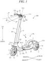
- FIG. 1 is a perspective view illustrating an overall configuration of a vehicle 100 according to the embodiment of the present invention
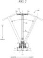
- FIG. 2 is a front view.
- three axial directions orthogonal to each other as illustrated are defined as the front-rear direction (length direction), the left-right direction (width direction), and the up-down direction (height direction) of the vehicle 100, and a configuration of each part will be described according to this definition.
- FIG. 1 is a view of the vehicle 100 viewed from a left obliquely front side
- FIG. 2 is a view of the vehicle 100 viewed from a front side.
- the vehicle 100 includes a front wheel 1 and rear wheels 2, and a frame FL included in a skeleton of the vehicle 100, and is entirely symmetric with respect to a center line CL1 passing through the center of the vehicle 100 in the left-right direction. More specifically, the front wheel 1 is arranged along the center line CL1, and the left and right rear wheels 2 are arranged at symmetrical positions across the center line CL1.
- the front wheel 1 has the same diameter as the rear wheels 2.
- the front wheel 1 may have a larger diameter or a smaller diameter than the rear wheels 2.
- the center line CL1 is a swing center of a connecting part 30, which will be described later, and extends at a downward slope toward a rear side.
- the center line CL1 may extend horizontally toward the rear side, or may extend at an upward slope toward the rear side.
- the frame FL includes a main frame 10 extending from the front wheel 1 to the rear wheel 2, and a vertical frame 20 erected above the front wheel 1.
- the main frame 10 includes a front frame 11 extending rearward from above the front wheel 1, and a rear frame 12 connected to the front frame 11 and extending toward the rear wheel 2.
- the front frame 11 is configured to be inclined at an upward slope (forward ascending) toward a front side.
- the front end portion 11a of the front frame 11 is located above the front wheel 1, and the rear end portion 11b extends substantially horizontally.
- the vertical frame 20 has a substantially columnar or cylindrical shaft 21 extending along an axial line CL2 inclined rearward by a predetermined angle relative to the gravitational direction such that the upper end portion is located rearward of the lower end portion.
- the shaft 21 passes through the front end portion 11a of the front frame 11 and is rotatably supported by the front frame 11 about the axial line CL2.
- a handlebar 22 is provided at an upper end portion of the shaft 21, and a pair of left and right front forks 23 are fixed to a lower end portion thereof.
- the vertical frame 20 may include a vertical pipe extending upward from the front end portion 11a of the front frame 11 and a shaft passing through the inside of the vertical pipe.
- the vertical pipe may be integrally provided in the front frame 11, and the shaft may be rotatably provided in the vertical pipe about the axial line CL2.
- a rotation shaft 1a of the front wheel 1 is rotatably supported by the pair of left and right front forks 23.
- the front wheel 1 is steered by a turning operation (steering) of the handlebar 22 about the axial line CL2.
- the handlebar 22 is a bar handle that extends substantially linearly in the left-right direction.
- a plastic or rubber grips 22a gripped by the user are provided at both left and right ends of the handlebar 22.
- Brake levers 22b are provided in front of the grips 22a.
- a traveling motor 4 in-wheel motor
- a brake unit 5 are housed inside the front wheel 1.
- the traveling motor 4 is arranged on the left side
- the brake unit 5 is arranged on the right side.
- the vehicle 100 is formed as an electric vehicle that travels by driving of the traveling motor 4.
- the handlebar 22 is provided with a throttle lever 24 at or near the grip 22a.
- the throttle lever 24 is configured to be operable by an occupant while gripping the grip 22a, and a travel command including an acceleration command of the vehicle 100 is inputted by operating the throttle lever 24.
- the throttle lever 24 is provided so as to be capable of adjusting an operation amount, and a command value is input so as to increase the driving force of the traveling motor 4 as the operation amount of the throttle lever 24 increases.
- the brake unit 5 is formed as, for example, a drum brake unit included in a drum brake.
- the rear wheels 2 are similarly provided with the brake units. These brake units 5 are operated by an operation of the brake levers 22b, and a braking force is applied to the front wheel 1 and the rear wheels 2.
- the traveling motor 4 as an electric motor may be provided in the rear wheels 2 instead of the front wheel 1, or in both the front wheel 1 and the rear wheels 2. When the traveling motors are provided in both the front wheel 1 and the rear wheels 2, the towing ability and the climbing ability of the vehicle 100 can be improved.
- a longitudinally elongated battery 6 is supported on the rear surface of the vertical frame 20 via a holder.
- the battery 6 is a secondary battery such as a lithium ion battery in which electric power supplied to the traveling motor 4 is stored.
- the battery 6 is connected to the traveling motor 4 via a power line passing through the vertical frame 20. Electric power supplied from the battery 6 to the traveling motor 4 is controlled by a power control unit not illustrated.
- the battery 6 may be disposed inside the vertical frame 20, or may be disposed around other structural members such as the main frame 10.
- the handlebar 22 is provided with a starter switch to instruct on/off of a main power supply, a blinker switch to notify of right/left turning, an accelerator lever to input a traveling command, and the like so as to be operable by the user.
- a display unit that displays vehicle information such as a remaining battery capacity and a set vehicle speed can also be provided.
- a pair of left and right blinker lamps that blink in response to an operation of the blinker switch is provided, and a headlight is provided at the upper end portion of the vertical frame 20.
- the rear frame 12 extends rearward through the inside of the left and right rear wheels 2.
- a support frame for example, a pair of front and rear support frames
- a rear wheel support portion extending in the left-right direction is joined to a rear portion (for example, a rear end portion) of the rear frame 12, and the rotation shaft 2a of the rear wheel 2 is rotatably supported by the rear wheel support portion.
- a step (footrest) 25 which is a plate member having a substantially rectangular shape in a plan view and extending in the front-rear direction from the rear frame 12 to the inner side of the left and right rear wheels 2 and in the left-right direction within the range of the length between the left and right rear wheels 2, is mounted.
- the step 25 is fixed to the support frame by welding or the like, whereby both ends of the step 25 in the front-rear direction are supported from the rear frame 12 via the support frames.
- the step 25 functions as a placement part on which both feet of the user (occupant) in a standing posture are placed, and the upper surface (placement surface) of the step 25 is configured as a horizontal surface parallel to the road surface 101.
- the length in the front-rear direction and the width in the left-right direction of the step 25 are defined so that a predetermined portion of the user's foot, for example, from the heel to the ball of the foot, can be placed.
- the front frame 11 and the rear frame 12 of the main frame 10 are connected to each other via the connecting part 30. That is, the front frame 11 is connected to the rear frame 12 via the connecting part 30 so as to be swingable in the left-right direction around the center line CL1 extending in the front-rear direction.
- the connecting part 30 has a Neidhart rubber spring 31 fixed to the bottom surface of the flat plate portion 112 of the front frame 11.
- FIG. 3 is a cross-sectional view illustrating a schematic configuration of the Neidhart rubber spring 31 provided in the connecting part 30.
- the Neidhart rubber spring 31 is incorporated in a case 311 having a substantially rectangular frame shape in a cross section and fixed to the rear end portion 11b of the front frame 11.
- a shaft 312 having a substantially circular cross section which is fixed to the front end portion of the rear frame 12 and extends in the front-rear direction along the center line CL1, is disposed.
- the front end portion of the rear frame 12 may be configured to have a substantially circular cross section, and may be used as the shaft 312.
- the Neidhart rubber spring 31 includes a substantially diamond-shaped cam block 313 spline-connected to the shaft 312 so as to be rotatable integrally with the shaft 312, and a rubber roller 314 disposed opposite to each surface formed in a concave shape of the cam block 313.
- FIG. 3 shows an initial state in which the front frame 11 is not swung, and at this time, the vertical frame 20 is not inclined in the left-right direction as shown by the solid line in FIG. 2 , and the vehicle 100 is in the reference posture.
- the rubber roller 314 is pressed between the case 311 and the cam block 313 to elastically deform, and the rubber roller 314 becomes an ellipse.
- the front frame 11 swings together with the vertical frame 20, and the vehicle 100 is in an inclined posture as shown by a dashed double-dotted line in FIG. 2 .
- the rotation resistance to the case 311 increases.
- the rubber roller 314 returns to its original shape by the elastic force, and the front frame 11 returns to the reference posture.
- the user riding on the vehicle 100 in a standing posture can easily turn the vehicle 100 in the left-right direction.
- the user slightly bends the knees and the ankles and inclines the upper body to the left or right.
- the vertical frame 20 can be swung together with the front frame 11 in a stable posture with both feet placed on the step 25 while the step 25 integrated with the rear frame 12 is kept horizontal, and the front wheel 1 can be inclined to the left and right.
- the vehicle 100 can be smoothly turned, and the turning performance is improved.
- the Neidhart rubber spring 31 is provided in the connecting part 30, when the front frame 11 is swung to the left and right from the reference posture, a restoring force acts on the front frame 11, and swinging of the front frame 11 can be favorably suppressed.
- the cam block 313 may be formed not in a quadrangular shape but in another polygonal shape (for example, a triangular shape). Instead of forming all surfaces of the cam block 313 in a concave shape, for example, two surfaces may be formed in a concave shape, and the rubber rollers 514 may be disposed to face these concave surfaces. As an example, it may be disposed to face two surfaces formed in a triangular cam block.
- the restoring force may be acted on the front frame 11 by using an elastic member such as a coil spring instead of the Neidhart rubber spring 31. That is, the configuration of a restoring force applying part is not limited to the Neidhart rubber spring 31.
- a load point (a center point of a load acting from a sole of the foot) acting on the step 25 due to the weight of the user in the standing posture is located in a triangular region connecting the ground point of the front wheel 1 and the respective ground points of the pair of left and right rear wheels 2 in a plan view.
- the user can ride on the vehicle 100 in a stable posture both while traveling and while stopping.
- the vertical frame 20 is provided so as to be rotatable rearward (the direction of an arrow "A" in FIG. 1 ) via a rotation mechanism 201 above the front end portion 11a of the front frame 11. Accordingly, the vehicle 100 can be brought into a folded posture from the traveling posture of FIG. 1 . In the folded posture, the vertical frame 20 is disposed between the left and right rear wheels 2 substantially parallel to the rear frame 12. The vehicle 100 can be easily transported by raising the vehicle 100 in the folded posture with the rear wheels 2 as a fulcrum and rolling the rear wheels 2 with the front wheel 1 disposed on the upper side. At a front end portion of the front frame 11, a handle 14 gripped during transportation of the vehicle 100 is provided.
- the handlebar 22 is provided to be steerable in the left-right direction with the axial line CL2 as the center, and the vertical frame 20 is provided to be swingable in the left-right direction with the center line CL1 as the center. Therefore, when the vehicle 100 starts moving or makes a turn, in a state in which the relationship between a steering angle and a swing angle is not appropriate, if the throttle lever 24 is operated (a throttle operation), the stability of the vehicle 100 may be degraded.
- the present embodiment is configured as follows.
- an operation amount of the handlebar 22 from the axial line L1, which extends in the front-rear direction, is defined as a steering angle ⁇ s.
- the steering angle ⁇ s at the time when the handlebar 22 is operated to the left is defined as a positive steering angle
- the steering angle ⁇ s at the time when the handlebar is operated to the right is defined as a negative steering angle.
- a swing amount of the vertical frame 20 from the axial line L2, which extends in the up-down direction is defined as a swing angle ⁇ r.
- the swing angle ⁇ r at the time when the vertical frame 20 is swung to the left is defined as a positive swing angle
- the swing angle ⁇ r at the time when the vertical frame 20 is swung to the right is defined as a negative swing angle
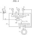
- FIG. 4 is a block diagram schematically illustrating a configuration of a controller 40 provided in a power control unit that controls driving of the traveling motor 4.
- the controller 40 includes a computer including a processing unit such as a CPU, a storage unit such as a ROM or a RAM, and other peripheral circuits. As illustrated in FIG. 4 , signals from a throttle sensor 41, a steering angle sensor 42, a swing angle sensor 43, and a vehicle speed sensor 44 are input to the controller 40.
- the throttle sensor 41 is provided in the throttle lever 24, and detects a command value (a throttle command value Th) corresponding to an operation amount on the throttle lever 24.
- the steering angle sensor 42 is provided on the shaft 21, for example, and detects a rotation amount of the shaft 21 by the operation on the handlebar 22, that is, the steering angle ⁇ s.
- the swing angle sensor 43 is provided in the connecting part 30, and detects the swing angle ⁇ r.
- the vehicle speed sensor 44 is provided on the rotation shaft 1a of the front wheel 1 or the traveling motor 4, and detects a vehicle speed v from the rotation speed of the rotation shaft 1a or the traveling motor 4.
- the controller 40 performs predetermined processing in accordance with input signals from these sensors 41 to 44, and controls driving of the traveling motor 4.
- the traveling motor 4 is, for example, an embedded magnet synchronous motor including a rotor and a stator arranged around the rotor, and is driven by electric power supplied from the battery 6 to a coil of the stator via the controller 40.
- a synchronous reluctance motor, a switched reluctance motor, or the like without a magnet can also be used as the traveling motor 4.
- the controller 40 calculates a correction coefficient ⁇ for correcting a throttle command value Th, based on the steering angle ⁇ s, the swing angle ⁇ r, and the vehicle speed v that have been detected by the sensors 42 to 44.
- a first correction coefficient ⁇ is calculated by a processing unit 40A with use of a function f ( ⁇ s, ⁇ r) with the steering angle ⁇ s and the swing angle ⁇ r as parameters
- a second correction coefficient ⁇ is calculated by a processing unit 40B with use of a function g(v) with the vehicle speed v as a parameter.
- a processing unit 40C calculates ⁇ to the power of ⁇ as the correction coefficient ⁇ .
- the processing unit 40C calculates a corrected throttle command value Th' (referred to as a motor command value) obtained by multiplying the throttle command value Th by the correction coefficient ⁇ , and outputs such a throttle command value Th' to a motor output unit 40D.
- the motor output unit 40D controls the traveling motor 4 so that the traveling motor 4 outputs driving torque in accordance with the motor command value Th'.
- FIGs. 5A and 5B are diagrams illustrating an example of characteristics indicating a relationship between the steering angle ⁇ s, the swing angle ⁇ r, and the first correction coefficient ⁇ .
- FIG. 5A illustrates a characteristic when the steering angle ⁇ s is equal to or larger than 0 degrees (when the vehicle is steered to the left)
- FIG. 5B illustrates a characteristic when the steering angle ⁇ s is equal to or smaller than 0 degrees (when the vehicle is steered to the right).
- characteristics f10 (a solid line), f11 (a dotted line), f12 (a dashed-dotted line), and f13 (a dashed double-dotted line) in FIG.
- FIG. 5A respectively indicate relationships between the swing angle ⁇ r and ⁇ , in cases where the steering angles ⁇ s are 0 degrees, 10 degrees, 20 degrees, and 30 degrees, and characteristics f20 (a solid line), f21 (a dotted line), f22 (a dashed-dotted line), and f23 (a dashed double-dotted line) in FIG. 5B respectively indicate relationships between the swing angle ⁇ r and ⁇ , in cases where the steering angles ⁇ s are 0 degrees, -10 degrees, -20 degrees, and -30 degrees. These characteristics are stored beforehand in a memory.
- the first correction coefficient ⁇ is calculated in a range that is larger than 0 and equal to or smaller than 1, and the correction coefficient ⁇ and the motor command value Th' increase, as the first correction coefficient ⁇ increases.
- ⁇ is equal to 1 or approximately 1 in a region where the swing angle ⁇ r is small, and ⁇ gradually decreases, as the magnitude (an absolute value) of the swing angle ⁇ r increases. Therefore, in a case where the magnitude of the swing angle ⁇ r becomes equal to or larger than a predetermined value, the motor command value Th' decreases, and the motor output is suppressed.
- ⁇ is substantially constant in a region where the swing angle ⁇ r is small in each of the characteristics f11 to f13 and f21 to f23 in a similar manner to the characteristics f10 and f20, and ⁇ gradually decreases as the magnitude of the swing angle ⁇ r increases.
- ⁇ decreases, as the steering angle ⁇ s increases. In other words, a decrease rate of ⁇ increases, as the steering angle ⁇ s increases.
- the correction coefficient ⁇ and the motor command value Th' decrease, as the magnitude of the steering angle ⁇ s increases, and the motor output is suppressed.
- FIG. 6 is a diagram illustrating an example of a characteristic indicating a relationship between the vehicle speed v and the second correction coefficient ⁇ .
- the second correction coefficient ⁇ is set in a range that is equal to or larger than 0 and equal to or smaller than 1.
- the second correction coefficient ⁇ is 1 or approximately 1 in a region where the vehicle speed v is low, and gradually decreases, as the vehicle speed v increases. More specifically, ⁇ is substantially constant in a region where the vehicle speed v is low, and when the vehicle speed v is equal to or higher than a predetermined value, ⁇ rapidly decreases, as the vehicle speed v increases.
- Characteristics h0 (a solid line), h1 (a dotted line), h2 (a dashed-dotted line), and h3 (a dashed double-dotted line) in FIG. 7 respectively indicate relationships between the swing angle and ⁇ , in a case where the vehicle speeds are 0 km/h, 10 km/h, 20 km/h, and 25 km/h.
- Such characteristics are obtained from the characteristics of the first correction coefficient ⁇ ( FIGs.
- the correction coefficient ⁇ increases, as the vehicle speed v increases. Accordingly, the motor command value Th' increases, as the vehicle speed v increases, and the degree of suppression of the motor output decreases.
- the motor command value Th' obtained at the time of operating the throttle lever 24 is smaller than that of a case where the steering direction and the swing direction are identical to each other, and the motor output is suppressed.
- the motor output is suppressed in a state in which the handlebar 22 is steered to the left and the vertical frame 20 is swung to the right. This decreases a change in the centrifugal force of the vehicle 100, and it becomes possible to prevent the stability of the vehicle 100 from being degraded.
- the degree of suppression of the motor output decreases, as the vehicle speed v increases. Therefore, the user is able to accelerate the vehicle 100 without feeling a sense of incongruity. That is, when the vehicle speed v increases, the change in the vehicle speed v with respect to the change in the throttle command value Th decreases. Therefore, if the motor output is suppressed, even though the user performs the throttle operation, the vehicle speed is less likely to increase, and the user is likely to feel a sense of incongruity. In this regard, in the present embodiment, as the vehicle speed v increases, a suppression rate of the motor output decreases, thereby suppressing the user from feeling the sense of incongruity.
- the controller 40 as a control unit calculates the correction coefficient ⁇ of the throttle command value Th, based on the steering angle ⁇ s, the swing angle ⁇ r, and the vehicle speed v. However, it may calculates the correction coefficient ⁇ based on the steering angle ⁇ s and the swing angle ⁇ r without considering the vehicle speed v.
- a swing angle represented by ⁇ rg in consideration of a gravity direction may be used.
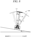
- FIG. 8 is a front view of the vehicle 100, which is located on a sloping ground where ⁇ g is an angle (an inclination angle) formed by a road surface with respect to a horizontal line.
- ⁇ g is an angle (an inclination angle) formed by a road surface with respect to a horizontal line.
- the left-right direction of the vehicle 100 coincides with an inclination direction of the road surface (an inclined surface).
- the angle of the vertical frame 20 from a reference line L3, which extends along the gravity direction is defined as a swing angle ⁇ rg. It is possible to calculate the swing angle ⁇ rg with use of a value of an inclination sensor (not illustrated) that detects the inclination angle ⁇ g of the road surface.
- the swing angle ⁇ rg of the vertical frame 20 with respect to the gravity direction with use of a detection value ( ⁇ g) of the inclination sensor and a detection value ( ⁇ r) of the swing angle sensor 43.
- a detection value ( ⁇ g) of the inclination sensor for example, a pendulum type sensor or a float type sensor provided on the rear frame 12 can be used.
- the swing angle ⁇ rg may be calculated with use of a gyro sensor or a bank angle sensor of gravity type. That is, any configuration may be applicable to a swing angle detection unit that detects the swing angle ⁇ rg from the reference line L3.
- the magnitude of the swing angle ⁇ rg obtained when the vertical frame 20 is swung on an upward inclination side is smaller than the magnitude of the swing angle ⁇ r obtained while the vehicle is traveling on a non-inclined ground, so that the output of the traveling motor 4 can be prevented from being excessively suppressed.
- the handlebar 22 serving as a steering part is configured in a bar shape, but the configuration of the steering part is not limited thereto.
- the step 25 (a placement part) is configured by a single plate member, but the placement part may be divided into left and right portions.
- the front wheel 1 is rotatably supported by the front frame 11 and the vertical frame 20 and is operably supported by the handlebar 22, but the configuration of a first member is not limited to that described above.
- the rear wheel 2 is rotatably supported by the rear frame 12, but the configuration of a second member is not limited thereto.
- the first member (front frame 11) is swingably connected to the second member (rear frame 12) about the center line CL1 (an axial line) through the connecting part 30 provided with the Neidhart rubber spring 31, a biasing part other than the Neidhart rubber spring may be used. Therefore, the configuration of the connecting part is not limited to that described above.
- the traveling motor 4 as a traveling actuator is provided at the front wheel 1, but as long as it is provided so as to drive at least one of the front wheel 1 and the rear wheel 2, the configuration of the traveling actuator is not limited to that described above. Since the brake (brake unit 5) contributes to the traveling operation of the vehicle, the brake is also included in the traveling actuator. Accordingly, the controller 40 may control the brake in addition to the traveling motor 4 or instead of the traveling motor 4. Instead of the traveling motor 4, a prime mover may be used as the traveling actuator.
- the travel command including the acceleration command is input by the operation of the throttle lever 24 provided on the handlebar 22, but the travel command may be input by the pedal depression operation, and the configuration of an input part is not limited to the above configuration.
- the travel command may include not only an acceleration command but also a deceleration command.
- the steering angle ⁇ s is detected by the steering angle sensor 42, but the configuration of a steering angle detection part is not limited to the above configuration.
- the swing angle ⁇ r is detected by the swing angle sensor 43, but the configuration of a swing angle detection part is not limited to the above configuration.
- the vehicle speed v is detected by the vehicle speed sensor 44, but the configuration of a vehicle speed detection part is not limited to the above configuration.
- the first correction coefficient ⁇ is calculated based on the characteristics of FIGs. 5A and 5B using the steering angle ⁇ s and the swing angle ⁇ r as parameters, but ⁇ may be calculated based on other characteristics.
- the second correction coefficient ⁇ is calculated based on the characteristic of FIG. 6 using the vehicle speed v as a parameter, but ⁇ may be calculated based on other characteristic.
- the correction coefficient ⁇ of the throttle command value Th is calculated using the first correction coefficient ⁇ and the second correction coefficient ⁇ , but the calculation formula of a correction coefficient for calculating the motor command value Th' is not limited to the above one.
- the correction coefficient ⁇ may be calculated without being divided into the first correction coefficient ⁇ and the second correction coefficient ⁇ .
- the correction coefficient ⁇ may be calculated using a map or the like without using a calculation formula. Therefore, the configuration of a control unit is not limited to the above configuration.
- the unstable vehicle attitude is caused by an inappropriate state of the steering angle and the swing angle with respect to the increase and decrease of the vehicle speed. Therefore, in order to enhance the stability of the vehicle attitude, torque may be applied to the shaft portion, which is the rotation center of the steering angle, or the shaft portion, which is the rotation center of the swing angle, or both, by an actuator (not shown) so as to assist in preventing the steering angle and the swing angle from becoming an inappropriate state. That is, for example, when the swing angle is insufficient, the torque may be applied in a direction in which the swing angle increases, while when the steering angle is too large, the torque may be applied in a direction in which the steering angle decreases, thereby assisting the steering. Thus, since the steering angle and the swing angle approach an appropriate state, the output suppression amount for the throttle operation by the above control is reduced.
- the vehicle 100 is configured to have a single front wheel 1 and a pair of left and right rear wheels 2.
- the vehicle can be configured to have a single front wheel and a single rear wheel, or a pair of front wheels and a single rear wheel.
- the single front wheel includes, for example, a pair of front wheels included in one position, that is, pair front wheels.
Landscapes
- Engineering & Computer Science (AREA)
- Mechanical Engineering (AREA)
- Power Engineering (AREA)
- Transportation (AREA)
- Automatic Cycles, And Cycles In General (AREA)
Applications Claiming Priority (1)
| Application Number | Priority Date | Filing Date | Title |
|---|---|---|---|
| PCT/JP2021/039774 WO2023073855A1 (fr) | 2021-10-28 | 2021-10-28 | Véhicule |
Publications (2)
| Publication Number | Publication Date |
|---|---|
| EP4424577A1 true EP4424577A1 (fr) | 2024-09-04 |
| EP4424577A4 EP4424577A4 (fr) | 2025-08-20 |
Family
ID=86157546
Family Applications (1)
| Application Number | Title | Priority Date | Filing Date |
|---|---|---|---|
| EP21962403.8A Pending EP4424577A4 (fr) | 2021-10-28 | 2021-10-28 | Véhicule |
Country Status (4)
| Country | Link |
|---|---|
| EP (1) | EP4424577A4 (fr) |
| JP (1) | JP7611418B2 (fr) |
| CN (1) | CN118139779A (fr) |
| WO (1) | WO2023073855A1 (fr) |
Families Citing this family (1)
| Publication number | Priority date | Publication date | Assignee | Title |
|---|---|---|---|---|
| US12509177B1 (en) * | 2024-10-16 | 2025-12-30 | Hyundai Motor Company | Body of vehicle |
Family Cites Families (7)
| Publication number | Priority date | Publication date | Assignee | Title |
|---|---|---|---|---|
| JP2005323431A (ja) * | 2004-05-07 | 2005-11-17 | Atex Co Ltd | 小型電動車の走行制御装置 |
| JP5285421B2 (ja) * | 2008-12-26 | 2013-09-11 | ヤマハ発動機株式会社 | 鞍乗型車両 |
| JP6307695B2 (ja) * | 2015-03-06 | 2018-04-11 | 株式会社エクォス・リサーチ | 車両 |
| JP7056349B2 (ja) | 2018-04-23 | 2022-04-19 | トヨタ自動車株式会社 | 自動傾斜車両 |
| NL2022121B1 (en) * | 2018-12-03 | 2020-06-30 | Carver B V | Self-balancing tilting vehicle with tilting speed and tilting torque controller |
| JP2020104640A (ja) | 2018-12-27 | 2020-07-09 | 株式会社エクォス・リサーチ | 車両 |
| JP6915179B1 (ja) | 2020-05-01 | 2021-08-04 | 本田技研工業株式会社 | 車両 |
-
2021
- 2021-10-28 WO PCT/JP2021/039774 patent/WO2023073855A1/fr not_active Ceased
- 2021-10-28 JP JP2023555973A patent/JP7611418B2/ja active Active
- 2021-10-28 CN CN202180103609.XA patent/CN118139779A/zh active Pending
- 2021-10-28 EP EP21962403.8A patent/EP4424577A4/fr active Pending
Also Published As
| Publication number | Publication date |
|---|---|
| WO2023073855A1 (fr) | 2023-05-04 |
| CN118139779A (zh) | 2024-06-04 |
| JP7611418B2 (ja) | 2025-01-09 |
| JPWO2023073855A1 (fr) | 2023-05-04 |
| EP4424577A4 (fr) | 2025-08-20 |
Similar Documents
| Publication | Publication Date | Title |
|---|---|---|
| EP2319750B1 (fr) | Véhicule à deux roues coaxiales et procédé pour le commander | |
| JP4534944B2 (ja) | 乗り物 | |
| CN101678872B (zh) | 同轴二轮车及其控制方法 | |
| JP6763318B2 (ja) | 自動傾斜車両 | |
| JP5418512B2 (ja) | 二輪車、二輪車用姿勢安定化装置及び二輪車用姿勢安定化方法 | |
| EP3305640A1 (fr) | Véhicule | |
| EP3505434A1 (fr) | Véhicule | |
| EP3812255A1 (fr) | Véhicule | |
| EP1426280A1 (fr) | Cycle à deux roues | |
| TWI735815B (zh) | 車輛 | |
| CN110386216A (zh) | 自动倾斜车辆 | |
| JP2013144513A (ja) | 車両 | |
| EP4424577A1 (fr) | Véhicule | |
| JP2008247149A (ja) | 車両 | |
| TWI684546B (zh) | 車輛 | |
| US20200004271A1 (en) | Method and device for lateral stabilization for a single-tracked motor vehicle at a standstill | |
| JP2014069674A (ja) | 自動車 | |
| JP5617652B2 (ja) | 車両 | |
| JP2010030440A (ja) | 同軸二輪車及びその制御方法 | |
| CN212369532U (zh) | 具有多轴旋转和基于自动平衡的驱动控制的运输装置 | |
| JP7780028B2 (ja) | リーン車両 | |
| JP2018134970A (ja) | リーン機構を備える車両 | |
| JP2018134969A (ja) | リーン機構を備える車両 |
Legal Events
| Date | Code | Title | Description |
|---|---|---|---|
| STAA | Information on the status of an ep patent application or granted ep patent |
Free format text: STATUS: THE INTERNATIONAL PUBLICATION HAS BEEN MADE |
|
| PUAI | Public reference made under article 153(3) epc to a published international application that has entered the european phase |
Free format text: ORIGINAL CODE: 0009012 |
|
| STAA | Information on the status of an ep patent application or granted ep patent |
Free format text: STATUS: REQUEST FOR EXAMINATION WAS MADE |
|
| 17P | Request for examination filed |
Effective date: 20240513 |
|
| AK | Designated contracting states |
Kind code of ref document: A1 Designated state(s): AL AT BE BG CH CY CZ DE DK EE ES FI FR GB GR HR HU IE IS IT LI LT LU LV MC MK MT NL NO PL PT RO RS SE SI SK SM TR |
|
| DAV | Request for validation of the european patent (deleted) | ||
| DAX | Request for extension of the european patent (deleted) | ||
| A4 | Supplementary search report drawn up and despatched |
Effective date: 20250721 |
|
| RIC1 | Information provided on ipc code assigned before grant |
Ipc: B62K 5/10 20130101AFI20250715BHEP Ipc: B62K 5/027 20130101ALI20250715BHEP Ipc: B62K 5/06 20060101ALI20250715BHEP Ipc: B62J 45/415 20200101ALI20250715BHEP Ipc: B62J 45/412 20200101ALI20250715BHEP Ipc: B62J 45/413 20200101ALI20250715BHEP Ipc: B62K 3/00 20060101ALI20250715BHEP |
|
| RIC1 | Information provided on ipc code assigned before grant |
Ipc: B62K 5/10 20130101AFI20260220BHEP Ipc: B62K 5/027 20130101ALI20260220BHEP Ipc: B62K 5/06 20060101ALI20260220BHEP Ipc: B62J 45/415 20200101ALI20260220BHEP Ipc: B62J 45/412 20200101ALI20260220BHEP Ipc: B62J 45/413 20200101ALI20260220BHEP Ipc: B62K 3/00 20060101ALI20260220BHEP Ipc: B60L 15/20 20060101ALI20260220BHEP |
|
| GRAP | Despatch of communication of intention to grant a patent |
Free format text: ORIGINAL CODE: EPIDOSNIGR1 |
|
| STAA | Information on the status of an ep patent application or granted ep patent |
Free format text: STATUS: GRANT OF PATENT IS INTENDED |