EP4424623A1 - Garnwickelmaschine - Google Patents
Garnwickelmaschine Download PDFInfo
- Publication number
- EP4424623A1 EP4424623A1 EP24156302.2A EP24156302A EP4424623A1 EP 4424623 A1 EP4424623 A1 EP 4424623A1 EP 24156302 A EP24156302 A EP 24156302A EP 4424623 A1 EP4424623 A1 EP 4424623A1
- Authority
- EP
- European Patent Office
- Prior art keywords
- yarn
- bobbin
- guide
- winding
- state
- Prior art date
- Legal status (The legal status is an assumption and is not a legal conclusion. Google has not performed a legal analysis and makes no representation as to the accuracy of the status listed.)
- Pending
Links
Images




Classifications
-
- B—PERFORMING OPERATIONS; TRANSPORTING
- B65—CONVEYING; PACKING; STORING; HANDLING THIN OR FILAMENTARY MATERIAL
- B65H—HANDLING THIN OR FILAMENTARY MATERIAL, e.g. SHEETS, WEBS, CABLES
- B65H67/00—Replacing or removing cores, receptacles, or completed packages at paying-out, winding, or depositing stations
- B65H67/04—Arrangements for removing completed take-up packages and or replacing by cores, formers, or empty receptacles at winding or depositing stations; Transferring material between adjacent full and empty take-up elements
- B65H67/044—Continuous winding apparatus for winding on two or more winding heads in succession
- B65H67/048—Continuous winding apparatus for winding on two or more winding heads in succession having winding heads arranged on rotary capstan head
-
- B—PERFORMING OPERATIONS; TRANSPORTING
- B65—CONVEYING; PACKING; STORING; HANDLING THIN OR FILAMENTARY MATERIAL
- B65H—HANDLING THIN OR FILAMENTARY MATERIAL, e.g. SHEETS, WEBS, CABLES
- B65H54/00—Winding, coiling, or depositing filamentary material
- B65H54/02—Winding and traversing material on to reels, bobbins, tubes, or like package cores or formers
- B65H54/28—Traversing devices; Package-shaping arrangements
- B65H54/34—Traversing devices; Package-shaping arrangements for laying subsidiary winding, e.g. transfer tails
- B65H54/343—Traversing devices; Package-shaping arrangements for laying subsidiary winding, e.g. transfer tails when starting winding on an empty bobbin
-
- B—PERFORMING OPERATIONS; TRANSPORTING
- B65—CONVEYING; PACKING; STORING; HANDLING THIN OR FILAMENTARY MATERIAL
- B65H—HANDLING THIN OR FILAMENTARY MATERIAL, e.g. SHEETS, WEBS, CABLES
- B65H57/00—Guides for filamentary materials; Supports therefor
- B65H57/04—Guiding surfaces within slots or grooves
-
- B—PERFORMING OPERATIONS; TRANSPORTING
- B65—CONVEYING; PACKING; STORING; HANDLING THIN OR FILAMENTARY MATERIAL
- B65H—HANDLING THIN OR FILAMENTARY MATERIAL, e.g. SHEETS, WEBS, CABLES
- B65H2701/00—Handled material; Storage means
- B65H2701/30—Handled filamentary material
- B65H2701/31—Textiles threads or artificial strands of filaments
- B65H2701/319—Elastic threads
Definitions
- the present invention mainly relates to a yarn winding machine including a plurality of bobbin holders.
- Patent Document 1 is Korean Patent No. 10-2000-0051263 .
- Patent Document 1 discloses a yarn winding machine that includes a first bobbin holder and a second bobbin holder.
- the yarn winding machine switches the positions of the bobbin holders. Then, the yarn winding machine presses a plate against yarn between the first bobbin holder and the second bobbin holder, and thereby winds the yarn around the bobbin of the second bobbin holder. Then, the rotation speed of the first bobbin holder is decreased to cut the yarn, and winding of the yarn on the bobbin of the second bobbin holder is started.
- the present invention has been made in view of the circumstances described above, and a main object thereof is to provide a yarn winding machine that switches bobbins during winding of yarn, with a configuration for manufacturing packages with excellent unwinding properties.
- a yarn winding machine having the following configuration. That is, the yarn winding machine manufactures a package, by rotating a first bobbin or a second bobbin in a first direction about an axial direction, to wind yarn on the first bobbin or the second bobbin.
- the yarn winding machine includes a first bobbin holder, a second bobbin holder, a bobbin holder moving mechanism, and a switching device.
- the first bobbin holder holds the first bobbin.
- the second bobbin holder holds the second bobbin.
- the bobbin holder moving mechanism rotates in the first direction about a direction parallel to axial directions of the first bobbin holder and the second bobbin holder to change positions of the first bobbin holder and the second bobbin holder to switch between a first state for manufacturing the package by winding the yarn on the first bobbin, and a second state for manufacturing the package by winding the yarn on the second bobbin.
- the switching device acts on the yarn between the first bobbin and the second bobbin during switching from the first state to the second state.
- the switching device includes a winding guide, a restriction guide, and a disengagement prevention guide.
- the winding guide presses, during switching from the first state to the second state, yarn between the first bobbin and the second bobbin to wind the yarn on the second bobbin.
- the restriction guide restricts, in the axial direction of the second bobbin holder, a movement range of the yarn on the second bobbin side, when the yarn between the first bobbin and the second bobbin breaks during switching from the first state to the second state.
- the disengagement prevention guide prevents disengagement of the yarn on the second bobbin side from the restriction guide, when the yarn between the first bobbin and the second bobbin breaks during switching from the first state to the second state.
- the disengagement prevention guide prevents disengagement of the yarn from the winding guide or the restriction guide. This makes disengagement of the yarn from the switching device during switching less frequent. Thus, it is possible to make the movement of the broken yarn small. Furthermore, restriction of the movement range of the broken yarn by the restriction guide makes it possible to make the movement of the broken yarn even smaller. Thus, the broken yarn can be wound at an appropriate position on the second bobbin while being suppressed from tangling. As a result, packages with excellent unwinding properties can be manufactured.
- the restriction guide may be a slit-shaped guide that restricts the movement range of the yarn in the axial direction of the second bobbin holder.
- the restriction guide with such a small width can heighten the effect of restricting the movement range of the broken yarn.
- the disengagement prevention guide may be a guide that interferes with the yarn on the second bobbin side, in a case where the yarn moves away from the winding guide, when the yarn between the first bobbin and the second bobbin breaks.
- the restriction guide may be provided separately from the winding guide.
- the restriction guide may be located closer to the second bobbin than the winding guide.
- the second bobbin may include, along the axial direction of the second bobbin, a yarn layer formation region around which the yarn is wound for manufacturing the package.
- the second bobbin may further include an end region located further outside than the yarn layer formation region in the axial direction of the second bobbin.
- the switching device may be configured to wind a yarn around the yarn layer formation region of the second bobbin.
- the switching device may be configured to wind the yarn in a surface region of the second bobbin having no groove and a constant diameter.
- the yarn winding machine may be configured to wind elastic yarn to manufacture the package.
- the present invention is applied to a type of yarn winding machine that winds elastic yarn to manufacture a package.
- FIG. 1 is a front view of a yarn winding machine 1 according to an embodiment of the present invention.
- FIG. 2 is a side view of the yarn winding machine 1.
- FIG. 3 is a block diagram of the yarn winding machine 1.
- upstream or downstream in a yarn running direction may simply be referred to as "upstream” or "downstream”.
- An unillustrated spinning machine is arranged upstream of the yarn winding machine 1 illustrated in FIG. 1 .
- the spinning machine manufactures yarn 93 and supplies the yarn 93 to the yarn winding machine 1.
- the yarn winding machine 1 winds the yarn 93 on a first bobbin 91 or a second bobbin 92 to manufacture a package 94.
- FIG. 1 illustrates a state where the yarn 93 is wound on the first bobbin 91 to form a yarn layer so that the package 94 is manufactured.
- the second bobbin 92 is in an empty bobbin state where the yarn 93 is not wound yet.
- the yarn 93 includes an elastic yarn such as spandex.
- the yarn 93 may be a synthetic yarn such as nylon or polyester.
- a plurality of the yarns 93 arranged in an axial direction of the first bobbin holder 41 (the second bobbin holder 42) are supplied from a yarn feed roller 100.
- a plurality of the first bobbins 91 are arranged in the axial direction of the first bobbin holder 41 (the second bobbin holder 42).
- the yarn winding machine 1 winds each of the plurality of yarns 93 on a corresponding one of the first bobbins 91 to manufacture a plurality of the packages 94.
- the yarn winding machine 1 will be described in detail below. As illustrated in FIGS. 1 to 3 , the yarn winding machine 1 includes a control device 50, a frame 11, a first housing 20, a second housing 30, and a turret plate (a bobbin holder moving mechanism) 40.
- the control device 50 is configured as a known computer including, for example, a CPU, RAM, and SSD.
- a CPU is a type of processor.
- Programs and data for controlling the yarn winding machine 1 are stored in the SSD in advance.
- the CPU loads the program into the RAM and executes the program.
- the control device 50 controls various devices included in the yarn winding machine 1.
- the control device 50 may include an HDD or a flash memory instead of the SSD.
- the frame 11 is a member that holds each component provided in the yarn winding machine 1.
- the first housing 20 is attached with a traverse device 21.
- the traverse device 21 reciprocating in a winding width direction (the axial direction of the first bobbin holder 41 or the second bobbin holder 42) with a traverse guide 23 being engaged with the yarn 93, each of the yarns 93 fed downstream is traversed.
- a yarn layer is formed on the first bobbin 91 or the second bobbin 92.
- the traverse device 21 includes a traverse cam 22 and the traverse guide 23.
- the traverse cam 22 is a roller-shaped member arranged parallel to the first bobbin 91 or the package 94. A spiral cam groove is formed on an outer peripheral surface of the traverse cam 22.
- the traverse cam 22 is rotationally driven by a traverse motor 51.
- Traverse motor 51 is controlled by the control device 50.
- the traverse guide 23 is a portion that is engaged with the yarn 93.
- a distal end of the traverse guide 23 includes, for example, a substantially U-shaped guide part that engages with the yarn 93 while sandwiching the yarn 93 in the winding width direction.
- a proximal end of the traverse guide 23 is positioned in a cam groove of the traverse cam 22. In this configuration, when the traverse cam 22 is rotationally driven, it is possible to reciprocate the traverse guide 23 in the winding width direction.
- the second housing 30 is rotatably attached with a contact roller 31.
- the contact roller 31 is driven to rotate with a contact with the yarn layer of the package 94 with a predetermined pressure to forward the yarn 93 from the traverse guide 23 to the yarn layer of the package 94 and form a yarn layer shape of the package 94 into a shape.
- the contact roller 31 may be rotationally driven by using a drive unit such as a motor.
- the yarn winding machine 1 includes a lifting and lowering device 60.
- the lifting and lowering device 60 lifts and lowers the first housing 20 and the second housing 30 all together.
- the first housing 20 and the second housing 30 are attached to a lifting and lowering member 65.
- a ball nut 61 is attached to the lifting and lowering member 65.
- a screw rod 62 is attached to the frame 11.
- the lifting and lowering motor 63 is controlled by the control device 50. It is noted that the lifting and lowering device 60 may be realized by using a cylinder instead of the ball screw.
- An operation panel 32 is provided on the second housing 30.
- the operation panel 32 is a device operated by an operator.
- the operator applies an instruction to the yarn winding machine 1 by operating the operation panel 32. Examples of the instruction applied by the operator include starting winding, stopping winding, and changing a winding condition.
- the turret plate 40 is a disk-shaped member.
- the turret plate 40 is rotatably attached to the frame 11.
- the turret plate 40 is rotatable about a rotation axis which is a normal line passing through the center of the disk.
- the turret plate 40 is rotationally driven by a turret motor 53 illustrated in FIG. 3 .
- the turret motor 53 is controlled by the control device 50.
- the first bobbin holder 41 and the second bobbin holder 42 are provided at two locations facing each other across the center of the disk, respectively.
- a plurality of the first bobbins 91 can be attached on the first bobbin holder 41 by being arranged in the axial direction of the first bobbin holder 41.
- a plurality of the second bobbins 92 can be attached on the second bobbin holder 42 by being arranged in the axial direction of the second bobbin holder 42.
- the direction of the rotational axis of the turret plate 40 is parallel to the axial direction of the first bobbin holder 41 or the second bobbin holder 42. Further, the rotation direction of the turret plate 40 upon changing the positions of the first bobbin holder 41 and the second bobbin holder 42 (upon switching from a first state to a second state, which will be described later) is a first direction (counterclockwise in FIG. 4 , which will be described later). It is noted that as long as the positions of the first bobbin holder 41 and the second bobbin holder 42 can be changed, another device may be used instead of the turret plate 40.
- the first bobbin holder 41 can rotate about the axial position of the first bobbin holder 41 with respect to the turret plate 40.
- the first bobbin holder 41 is rotationally driven by a first bobbin holder motor 54 illustrated in FIG. 3 .
- the second bobbin holder 42 can rotate about the axial position of the second bobbin holder 42 with respect to the turret plate 40.
- the second bobbin holder 42 is rotationally driven by a second bobbin holder motor 55 illustrated in FIG. 3 .
- the first bobbin holder motor 54 and the second bobbin holder motor 55 are controlled by the control device 50.
- the first bobbin holder 41 and the first bobbin 91 rotate in the first direction about the axial direction (the axial direction of the first bobbin 91, the axial direction of the first bobbin holder 41).
- the second bobbin holder 42 and the second bobbin 92 rotate in the first direction about the axial direction (the axial direction of the second bobbin 92, the axial direction of the second bobbin holder 42).
- the rotation directions of the first bobbin 91 and the second bobbin 92 when the package 94 is manufactured are the same as the rotation direction of the turret plate 40 when changing the positions of the first bobbin holder 41 and the second bobbin holder 42.
- the first bobbin holder 41 and the second bobbin holder 42 are in a state of being arranged vertically. In this state, a higher position at which the first bobbin holder 41 is located is a winding position, and a lower position at which the second bobbin holder 42is located is a standby position.
- the yarn winding machine 1 winds the yarn 93 on the first bobbin holder 41 at the winding position to manufacture the package 94.
- the upper diagram in FIG. 4 illustrates the first state for manufacturing the package 94 by winding the yarn 93 on the first bobbin 91 of the first bobbin holder 41.
- the traverse device 21 traverses the yarn 93 being wound around the first bobbin 91.
- the contact roller 31 contacts the first bobbin 91 (the package 94) and sends the yarn 93 being traversed by the traverse device 21 to the first bobbin 91 (the package 94). In this way, the yarn 93 is wound around the first bobbin 91 for manufacturing the package 94.
- the lifting and lowering device 60 moves the first housing 20 and the second housing 30 upward (the lower diagram in FIG. 4 ). Further, the turret plate 40 driven by the turret motor 53 switches the positions of the first bobbin holder 41 and the second bobbin holder 42 (the lower diagram in FIG. 4 ). As a result, the second bobbin holder 42 is located at the winding position, and the first bobbin holder 41 is located at the standby position. At this time, a part of the yarn 93 is stretched between the first bobbin 91 (the package 94) and the second bobbin 92.
- connecting yarn 93a the part of the yarn 93 will be referred to as connecting yarn 93a.
- the connecting yarn 93a when viewed in the axial direction of the first bobbin holder 41 or the second bobbin holder 42 (for example, the lower diagram in FIG. 4 ), the connecting yarn 93a is located on a first side (the left side in FIG. 4 ) in the horizontal direction with respect to the axial position of the second bobbin holder 42, and the connecting yarn 93a is wound around the package 94 from the first side (the left side in FIG. 4 ) in the horizontal direction with respect to the axial position of the first bobbin holder 41.
- the lifting and lowering device 60 moves the first housing 20 and the second housing 30 downward (the upper view of FIG. 5 ). Furthermore, the second bobbin holder motor 55 rotationally drives the second bobbin holder 42 (the upper diagram in FIG. 5 ). In this state, the switching device 70 acts on the connecting yarn 93a (the upper diagram in FIG. 5 ).
- the switching device 70 presses the connecting yarn 93a in such a manner that the connecting yarn 93a is pressed against the second bobbin 92.
- the winding angle of the yarn 93 with respect to the second bobbin 92 becomes larger than before being pressed by the switching device 70.
- the winding angle is the angle of a part of the yarn 93 that has been wound on the second bobbin 92, when viewed in the axial direction of the second bobbin holder 42.
- the yarn 93 is wound in a yarn layer formation region of the second bobbin 92 provided along the axial direction of the second bobbin 92.
- the yarn layer formation region is a region along the axial direction of the second bobbin 92 in which the yarn 93 is wound for manufacturing the package 94. Further, a region located further outside than the yarn layer formation region in the axial direction of the second bobbin 92 is referred to as an end region. Some bobbins have a groove (slit) formed in the end region, and the yarn may be guided to the groove to be fixed to the bobbin. In contrast, in the second bobbin 92 of the present embodiment, both of the yarn layer formation region and the end region do not include any groove.
- the second bobbin 92 has a cylindrical shape and has a constant diameter in a region where there is no groove.
- the switching device 70 includes an unillustrated actuator (a cylinder, a solenoid, a motor, or the like) that realizes pressing of the connecting yarn 93a.
- the actuator of the switching device 70 is controlled by the control device 50. While the switching device 70 presses the connecting yarn 93a, the first bobbin holder motor 54 decreases the rotational speed of the first bobbin holder 41. Thereby, the yarn 93 can be wound around the second bobbin 92. Furthermore, winding the yarn 93 around the second bobbin 92 increases the tension applied to the connecting yarn 93a, and as a result, the connecting yarn 93a breaks.
- the connecting yarn 93a Since the connecting yarn 93a is bent by the switching device 70, the connecting yarn 93a basically breaks between the contact point with the switching device 70 and the first bobbin 91. Of the broken yarns 93, the yarn 93 on the second bobbin holder 42 side is wound around the second bobbin 92. Further, the broken yarns 93 on the first bobbin holder 41 side are wound around the package 94. In this way, switching from the first state to the second state is achieved.
- the yarn winding machine 1 winds the yarn 93 on the second bobbin 92 to manufacture the package 94 (the lower diagram in FIG. 5 ). Further, the fully wound package 94 of the first bobbin holder 41 at the standby position is removed, and a new first bobbin 91 around which the yarn 93 is not yet wound is attached to the first bobbin holder 41.
- FIG. 6 illustrates a yarn winding machine 1 according to a comparative example.
- the yarn winding machine 1 according to the comparative example includes a switching device 170.
- the upper diagram of FIG. 6 illustrates a situation in which the switching device 170 is not in contact with the connecting yarn 93a at a time of breakage of the connecting yarn 93a as a result of winding the yarn 93 around the second bobbin 92 and then decreasing the rotational speed of the first bobbin holder 41.
- the yarn 93 on the second bobbin 92 side may be wound at an inappropriate position in the second bobbin 92 (a position outside the winding width of the yarn 93), or the yarn 93 may be wound around the second bobbin 92 in a tangled state.
- the package 94 is manufactured by winding the yarn 93 around the second bobbin 92 in such a state, the risk of tangling between the yarn 93 wound at the inappropriate position or the tangled yarn 93 and the yarn 93 wound thereon may increase. The tangling of the yarn 93 results in the manufactured package 94 with low unwinding properties.
- the switching device 70 of the present embodiment includes a plurality of yarn guides which decrease the risk of occurrence of such a situation.
- the detailed configuration of the switching device 70 will be described below.
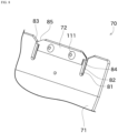
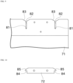
- the switching device 70 includes a first guide member 71 and a second guide member 72.
- a winding guide 81, a restriction guide 82, and a tapered portion 83 are formed in the first guide member 71.
- a disengagement prevention guide 84 and a slope portion 85 are formed in the second guide member 72.
- the first guide member 71 is a member that serves as a base of the switching device 70.
- the first guide member 71 is a member that moves by being driven by the actuator described above.
- the second guide member 72 is fixed to the first guide member 71 by a fastener 111.
- the first guide member 71 has a tapped hole
- the second guide member 72 has a through hole.
- the fixing method is not limited to this, and the first guide member 71 and the second guide member 72 may be fixed to each other with a bolt and a nut, or a rivet, or may be welded to each other. Fixing the first guide member 71 to the second guide member 72 makes it possible for the first guide member 71 and the second guide member 72 (i.e., the winding guide 81, the restriction guide 82, and the disengagement prevention guide 84) to move together.
- the first guide member 71 and the second guide member 72 are members formed from a plate material.
- the first guide member 71 and the second guide member 72 are arranged on top of each other in the thickness direction.
- the second guide member 72 is arranged upstream of the first guide member 71 in the running direction of the yarn 93.
- the winding guide 81 and the disengagement prevention guide 84 are arranged on top of each other in the thickness direction (in particular, the disengagement prevention guide 84 is arranged on the upstream side).
- the restriction guide 82 and the disengagement prevention guide 84 are arranged on top of each other in the thickness direction (in particular, the disengagement prevention guide 84 is arranged on the upstream side).
- the second guide member 72 may be arranged downstream of the first guide member 71.
- the plurality of second bobbins 92 are arranged along the axial direction of the second bobbin holder 42.
- a combination of the winding guide 81, the restriction guide 82, and the disengagement prevention guide 84 is provided for each of the second bobbins 92.
- the switching device 70 of the present embodiment includes a plurality of combinations of the winding guide 81, the restriction guide 82, and the disengagement prevention guide 84.
- a plurality of combinations of the winding guide 81 and the restriction guide 82 may be formed together in one first guide member 71, or each of the combinations may be formed in a corresponding one of separate first guide members 71.
- a plurality of disengagement prevention guides 84 may be formed together in one second guide member 72 or each of the disengagement prevention guides 84 may be formed in a corresponding one of separate second guide members 72.
- a slit-shaped recess is formed in the first guide member 71.
- the slit-shaped recess is formed at a position aligned with the center of the yarn layer formation region in the axial direction of the second bobbin 92.
- the winding guide 81 is a portion of the contour of the slit-shaped recess that is closest to the base (a portion opposite to the distal end).
- the winding guide 81 formed in the first guide member 71 comes into contact with and presses the connecting yarn 93a during switching from the first state to the second state. Thereby, the connecting yarn 93a can be wound around the second bobbin 92.
- the portion other than the winding guide 81 of the slit-shaped recesses formed in the first guide member 71 is the restriction guide 82.
- the winding guide 81 presses the connecting yarn 93a. That is, the connecting yarn 93a is located in a region formed by the winding guide 81 and the restriction guide 82.
- the connecting yarn 93a breaks at a location between the winding guide 81 and the first bobbin 91.
- the restriction guide 82 restricts, in the winding width direction (the axial direction of the second bobbin holder 42), movement of the broken yarn 93 on the second bobbin 92 side.
- the yarn 93 is wound around the second bobbin 92 at an appropriate position (in a range included in the winding width of the yarn 93), and the risk of tangling of the yarn 93 when the yarn 93 is wound around the second bobbin 92 is reduced.
- the connecting yarn 93a breaks at a location closer to the first bobbin 91 than the switching device 70, the broken yarn 93 on the second bobbin 92 side tends to move largely.
- the above-mentioned effect of the restriction guide 82 is even more beneficial.
- the tapered portion 83 is formed to be more to the distal end side than the restriction guide 82.
- the tapered portion 83 has a tapered shape that widens towards the distal end of the switching device 70. In other words, the width of the tapered portion 83 increases towards the distal end of the switching device 70.
- the restriction guide 82 is connected to the base of the tapered portion 83.
- the width of the tapered portion 83 includes a portion wider than the slit width of the tapered portion 83. Since the restriction guide 82 is provided at the center of the yarn layer formation region in the axial direction of the second bobbin 92, during switching from the first state to the second state, the traverse operation of the traverse device 21 guides the yarn 93 into the tapered portion 83.
- the yarn 93 is guided to the tapered portion 83 by its own tension.
- the connecting yarn 93a is guided by the tapered portion 83, passes through the restriction guide 82, and comes into contact with the winding guide 81. That is, the tapered portion 83 has a function of guiding the connecting yarn 93a toward the winding guide 81.
- the shape of the winding guide 81, the restriction guide 82, or the tapered portion 83 may be different from that of the present embodiment. Further, the first guide member 71 may not include the tapered portion 83.
- the disengagement prevention guide 84 formed in the second guide member 72 has a portion facing the winding guide 81.
- the disengagement prevention guide 84 closes a part of the open side of the slit-shaped recess formed by the winding guide 81 and the restriction guide 82.
- the disengagement prevention guide 84 suppresses disengagement of the yarn 93 on the second bobbin 92 side from the winding guide 81 and the restriction guide 82 when the connecting yarn 93a breaks during switching from the first state to the second state.
- the yarn 93 on the second bobbin 92 side is wound around the second bobbin 92 at an appropriate position (in a range included in the winding width of the yarn 93), and the risk of tangling of the yarn 93 on the second bobbin 92 side when the yarn 93 on the second bobbin 92 side is wound around the second bobbin 92 is reduced.
- the connecting yarn 93a breaks at a location closer to the first bobbin 91 than the switching device 70, the broken yarn 93 on the second bobbin 92 side tends to move largely and disengage from the restriction guide 82.
- the above-mentioned effect of the disengagement prevention guide 84 is even more beneficial.
- the centrifugal force of the rotation of the second bobbin holder 42 may largely move the broken yarn 93 on the second bobbin 92 side in such a manner that the broken yarn 93 swings radially outward.
- the disengagement prevention guide 84 interferes with the yarn 93 on the second bobbin side that swings radially outward.
- the slope portion 85 is formed on the distal end side of the disengagement prevention guide 84.
- the slope portion 85 has a shape that slopes so as to widen towards the base.
- the slope portion 85 guides the connecting yarn 93a toward the winding guide 81 and the restriction guide 82 along the slope.
- the switching device 70 (the first guide member 71) of the present embodiment has a portion having an arc shape when viewed in the axial direction of the second bobbin holder 42.
- the arc-shaped portion helps the distal end of the switching device 70 to be placed closer to the second bobbin holder 42.
- the location where movement in the winding width direction is restricted by the first guide member 71 is close to the location where the broken yarn 93 is wound.
- the yarn 93 can be wound around the second bobbin 92 while being prevented from largely moving.
- the yarn winding machine 1 differs from the above embodiment in that the winding guide 81 is provided separately from the restriction guide 82.
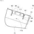
- the switching device 70 of the variation further includes a third guide member 73.
- the restriction guide 82 is formed in the first guide member 71
- the disengagement prevention guide 84 is formed in the second guide member 72
- the winding guide 81 is formed in the third guide member 73.
- the third guide member 73 (the winding guide 81) is arranged downstream of the first guide member 71 (the restriction guide 82) in the running direction of the yarn 93 before breakage.
- the distance from the restriction guide 82 to the second bobbin 92 is shorter than the distance from the winding guide 81 to the second bobbin 92.
- the restriction guide 82 is located closer to the second bobbin 92 than the winding guide 81.
- the third guide member 73 is fixed to the first guide member 71 by a fastener 112.
- a fixing structure between the first guide member 71 and the third guide member 73 is similar to the fixing structure between the first guide member 71 and the second guide member 72.
- the third guide member 73 has a bent portion.
- the base side of the third guide member 73 is in contact with the first guide member 71, and the distal end side of the third guide member 73 is spaced from the first guide member 71.
- the first guide member 71, the second guide member 72, and the third guide member 73 move together.
- the winding guide 81 of the variation is formed at the distal end of the third guide member 73, and has a V-shape that has a width increasing towards the distal end side.
- This configuration makes it possible to guide the connecting yarn 93a toward the inside of the V-shaped groove, when the switching device 70 presses the connecting yarn 93a.
- the winding guide 81 is formed at a position aligned with the center of the yarn layer formation region in the axial direction of the bobbin. This makes it difficult for the connecting yarn 93a to move to a position outside the winding width when the yarn breaks.
- the first guide member 71 moves toward the connecting yarn 93a to cause the winding guide 81 of the third guide member 73 to press the connecting yarn 93a and wind the yarn 93 around the second bobbin 92 by a predetermined angle. Then, the rotational speed of the first bobbin holder 41 is decreased to change the yarn path. The yarn path is bent by the winding guide 81. Thus, a strong force is applied to the connecting yarn 93a at the point of contact with the winding guide 81, and thus the connecting yarn 93a breaks at a location between the winding guide 81 and the first bobbin 91.
- the movement of the broken yarn 93 in the winding width direction is restricted by the restriction guide 82 of the first guide member 71, as in the above embodiment. Furthermore, the disengagement prevention guide 84 of the second guide member 72 suppresses the broken yarn 93 from disengaging from the switching device 70, and from swinging outward in the radial direction. Thus, the yarn 93 can be wound around the second bobbin 92 while being prevented from largely moving.
- the shape of the winding guide 81 is merely an example, and the winding guide 81 may be a rectangular groove instead of the V-shaped groove, or a groove may not be formed.
- the yarn winding machine 1 manufactures the package 94, by rotating the first bobbin 91 or the second bobbin 92 in the first direction about the axial direction, to wind yarn 93 on the first bobbin 91 or the second bobbin 92.
- the yarn winding machine 1 includes the first bobbin holder 41, the second bobbin holder 42, the turret plate 40, and the switching device 70.
- the first bobbin holder 41 holds the first bobbin 91.
- the second bobbin holder 42 holds the second bobbin 92.
- the turret plate 40 rotates in the first direction about a direction parallel to axial directions of the first bobbin holder 41 and the second bobbin holder 42 to change positions of the first bobbin holder 41 and the second bobbin holder 42 to switch between a first state for manufacturing the package 94 by winding the yarn 93 on the first bobbin 91, and a second state for manufacturing the package 94 by winding the yarn 93 on the second bobbin 92.
- the switching device 70 acts on the yarn 93 between the first bobbin 91 and the second bobbin 92 during switching from the first state to the second state.
- the switching device 70 includes the winding guide 81, the restriction guide 82, and the disengagement prevention guide 84.
- the winding guide 81 presses, during switching from the first state to the second state, the connecting yarn 93a between the first bobbin 91 and the second bobbin 92 to wind the yarn 93 on the second bobbin 92.
- the restriction guide 82 restricts, in the axial direction of the second bobbin holder 42, a movement range of the yarn 93 on the second bobbin 92 side, when the connecting yarn 93a between the first bobbin 91 and the second bobbin 92 breaks during switching from the first state to the second state.
- the disengagement prevention guide 84 prevents disengagement of the yarn 93 on the second bobbin 92 side from the restriction guide 82, when the connecting yarn 93a between the first bobbin 91 and the second bobbin 92 breaks during switching from the first state to the second state.
- the disengagement prevention guide 84 prevents disengagement of the yarn from the winding guide 81 or the restriction guide 82. This makes disengagement of the connecting yarn 93a from the switching device 70 during switching less frequent. Thus, it is possible to make the movement of the broken yarn 93 small. Furthermore, restriction of the movement range of the broken yarn 93 by the restriction guide 82 makes it possible to make the movement of the broken yarn 93 even smaller. Thus, the broken yarn 93 can be wound at an appropriate position on the second bobbin 92 while being suppressed from tangling. As a result, packages 94 with excellent unwinding properties can be manufactured.
- the restriction guide 82 is a slit-shaped guide restricts the movement range of the yarn 93 in the axial direction of the second bobbin holder 42.
- the restriction guide 82 with such a small width can heighten the effect of restricting the movement range of the broken yarn 93.
- the disengagement prevention guide 84 is a guide that interferes with the connecting yarn 93a on the second bobbin 92 side guided by the winding guide 81, in a case where the yarn 93a moves away from the winding guide 81, when the connecting yarn 93a between the first bobbin 91 and the second bobbin 92 breaks.
- the restriction guide 82 is provided separately from the winding guide 81.
- the restriction guide 82 is located closer to the second bobbin 92 than the winding guide 81.
- the second bobbin 92 includes, along the axial direction of the second bobbin 92, the yarn layer formation region around which the yarn 93 is wound for manufacturing the package 94, and the end region located further outside than the yarn layer formation region in the axial direction of the second bobbin 92.
- the switching device 70 winds the yarn 93 around the yarn layer formation region of the second bobbin 92.
- the switching device 70 winds the yarn 93 in a region of the second bobbin 92 having no groove and a constant diameter.
- the yarn winding machine 1 winds elastic yarn 93 to manufacture the package 94.
- the present technique is applied to a type of yarn winding machine 1 that winds elastic yarn to manufacture a package 94.
- switching the bobbin holder subjected to winding the yarn 93 from the first bobbin holder 41 to the second bobbin holder 42 is performed, in a state where the first bobbin holder 41 holding a fully wound package 94 is at the standby position and the second bobbin holder 42 to be used for producing a new package 94 is at the winding position.
- the positions of the first bobbin holder 41 and the second bobbin holder 42 when switching the bobbin holder subjected to winding the yarn 93 is performed are not limited to those.
- the traverse device 21 of the above embodiment is of cam drum type, the traverse device 21 may have a different configuration as long as it is possible to reciprocate the traverse guide 23 in the winding width direction.
- a belt-type traverse device instead of the traverse device 21, may be used.
Landscapes
- Replacing, Conveying, And Pick-Finding For Filamentary Materials (AREA)
Applications Claiming Priority (2)
| Application Number | Priority Date | Filing Date | Title |
|---|---|---|---|
| JP2023030385 | 2023-02-28 | ||
| JP2023194085A JP2024122851A (ja) | 2023-02-28 | 2023-11-15 | 糸巻取機 |
Publications (1)
| Publication Number | Publication Date |
|---|---|
| EP4424623A1 true EP4424623A1 (de) | 2024-09-04 |
Family
ID=89854688
Family Applications (1)
| Application Number | Title | Priority Date | Filing Date |
|---|---|---|---|
| EP24156302.2A Pending EP4424623A1 (de) | 2023-02-28 | 2024-02-07 | Garnwickelmaschine |
Country Status (2)
| Country | Link |
|---|---|
| EP (1) | EP4424623A1 (de) |
| KR (1) | KR20240133587A (de) |
Cited By (1)
| Publication number | Priority date | Publication date | Assignee | Title |
|---|---|---|---|---|
| CN119976532A (zh) * | 2025-04-17 | 2025-05-13 | 江苏恒力化纤股份有限公司 | 一种卷绕机纸管尾丝的切丝装置及其切丝方法 |
Citations (4)
| Publication number | Priority date | Publication date | Assignee | Title |
|---|---|---|---|---|
| KR20000051263A (ko) | 1999-01-20 | 2000-08-16 | 전영도 | 탄성사의 권취장치 및 권취방법 |
| EP1065163A2 (de) * | 1999-07-01 | 2001-01-03 | Murata Kikai Kabushiki Kaisha | Aufwickelmaschine und Verfahren dafür zum Bilden einer Fadenreserve |
| KR20030042587A (ko) * | 2001-11-23 | 2003-06-02 | 주식회사 효성 | 탄성사의 방사 권취기 및 그 권취 방법과 이를 통해감겨진 탄성사 권사체 |
| KR100478654B1 (ko) * | 2002-10-16 | 2005-03-28 | 일진에이테크 주식회사 | 탄성사의 권취 장치 |
-
2024
- 2024-02-06 KR KR1020240018095A patent/KR20240133587A/ko active Pending
- 2024-02-07 EP EP24156302.2A patent/EP4424623A1/de active Pending
Patent Citations (4)
| Publication number | Priority date | Publication date | Assignee | Title |
|---|---|---|---|---|
| KR20000051263A (ko) | 1999-01-20 | 2000-08-16 | 전영도 | 탄성사의 권취장치 및 권취방법 |
| EP1065163A2 (de) * | 1999-07-01 | 2001-01-03 | Murata Kikai Kabushiki Kaisha | Aufwickelmaschine und Verfahren dafür zum Bilden einer Fadenreserve |
| KR20030042587A (ko) * | 2001-11-23 | 2003-06-02 | 주식회사 효성 | 탄성사의 방사 권취기 및 그 권취 방법과 이를 통해감겨진 탄성사 권사체 |
| KR100478654B1 (ko) * | 2002-10-16 | 2005-03-28 | 일진에이테크 주식회사 | 탄성사의 권취 장치 |
Cited By (1)
| Publication number | Priority date | Publication date | Assignee | Title |
|---|---|---|---|---|
| CN119976532A (zh) * | 2025-04-17 | 2025-05-13 | 江苏恒力化纤股份有限公司 | 一种卷绕机纸管尾丝的切丝装置及其切丝方法 |
Also Published As
| Publication number | Publication date |
|---|---|
| KR20240133587A (ko) | 2024-09-04 |
Similar Documents
| Publication | Publication Date | Title |
|---|---|---|
| WO2012096040A1 (ja) | 紡糸巻取装置及び紡糸巻取設備 | |
| CN101061048B (zh) | 用于操作生产交叉卷绕筒子的纺织机的工作站的方法和装置 | |
| EP4424623A1 (de) | Garnwickelmaschine | |
| JP2013023787A (ja) | 紡糸巻取機 | |
| EP2105399B1 (de) | Garnwicklungsvorrichtung und Garnwicklungsverfahren | |
| EP1717182B1 (de) | Vorrichtung zur Beseitigung von Fadenlockerungen in einer Textilmaschine | |
| WO2004018340A1 (ja) | レボルビング型糸条巻取機 | |
| JP2024122851A (ja) | 糸巻取機 | |
| EP1995201A2 (de) | Garnaufwickler | |
| US5566904A (en) | Method for sequentially winding elastic yarn on a plurality of bobbin holders | |
| EP3363756B1 (de) | Garnwickler | |
| KR101213126B1 (ko) | 실 권취 장치 | |
| CN102530640A (zh) | 丝线卷取机 | |
| JP2024038600A (ja) | 糸巻取機 | |
| JP7733594B2 (ja) | 糸巻取機 | |
| US20090134263A1 (en) | Method for Avoiding Ribbon Windings | |
| JP2010030704A (ja) | 糸状態検知装置、及び、これを備えた繊維機械 | |
| EP4249414B1 (de) | Garnwickelmaschine | |
| CN118561090A (zh) | 纱线卷取机 | |
| CN116730105A (zh) | 丝线卷绕机 | |
| EP2910507B1 (de) | Garnsammelvorrichtung, Garnwickeleinheit damit und Garnwickelmaschine damit | |
| EP4245705A1 (de) | Garnwickelmaschine | |
| JP3275189B2 (ja) | 高伸度糸条の巻取方法ならびに装置 | |
| EP3988488B1 (de) | Garnwickler | |
| JP2024175536A (ja) | 糸巻取装置 |
Legal Events
| Date | Code | Title | Description |
|---|---|---|---|
| PUAI | Public reference made under article 153(3) epc to a published international application that has entered the european phase |
Free format text: ORIGINAL CODE: 0009012 |
|
| STAA | Information on the status of an ep patent application or granted ep patent |
Free format text: STATUS: THE APPLICATION HAS BEEN PUBLISHED |
|
| AK | Designated contracting states |
Kind code of ref document: A1 Designated state(s): AL AT BE BG CH CY CZ DE DK EE ES FI FR GB GR HR HU IE IS IT LI LT LU LV MC ME MK MT NL NO PL PT RO RS SE SI SK SM TR |
|
| STAA | Information on the status of an ep patent application or granted ep patent |
Free format text: STATUS: REQUEST FOR EXAMINATION WAS MADE |
|
| 17P | Request for examination filed |
Effective date: 20250225 |
|
| GRAP | Despatch of communication of intention to grant a patent |
Free format text: ORIGINAL CODE: EPIDOSNIGR1 |
|
| STAA | Information on the status of an ep patent application or granted ep patent |
Free format text: STATUS: GRANT OF PATENT IS INTENDED |
|
| INTG | Intention to grant announced |
Effective date: 20260212 |
|
| RIN1 | Information on inventor provided before grant (corrected) |
Inventor name: YOSHINO, KYOHEI Inventor name: KAWAI, MASASHI |