EP4424931A1 - Engin de chantier - Google Patents
Engin de chantier Download PDFInfo
- Publication number
- EP4424931A1 EP4424931A1 EP22893138.2A EP22893138A EP4424931A1 EP 4424931 A1 EP4424931 A1 EP 4424931A1 EP 22893138 A EP22893138 A EP 22893138A EP 4424931 A1 EP4424931 A1 EP 4424931A1
- Authority
- EP
- European Patent Office
- Prior art keywords
- construction machine
- brake light
- auxiliary brake
- work
- multifunctional auxiliary
- Prior art date
- Legal status (The legal status is an assumption and is not a legal conclusion. Google has not performed a legal analysis and makes no representation as to the accuracy of the status listed.)
- Pending
Links
Images


Classifications
-
- B—PERFORMING OPERATIONS; TRANSPORTING
- B60—VEHICLES IN GENERAL
- B60Q—ARRANGEMENT OF SIGNALLING OR LIGHTING DEVICES, THE MOUNTING OR SUPPORTING THEREOF OR CIRCUITS THEREFOR, FOR VEHICLES IN GENERAL
- B60Q1/00—Arrangement of optical signalling or lighting devices, the mounting or supporting thereof or circuits therefor
- B60Q1/26—Arrangement of optical signalling or lighting devices, the mounting or supporting thereof or circuits therefor the devices being primarily intended to indicate the vehicle, or parts thereof, or to give signals, to other traffic
- B60Q1/44—Arrangement of optical signalling or lighting devices, the mounting or supporting thereof or circuits therefor the devices being primarily intended to indicate the vehicle, or parts thereof, or to give signals, to other traffic for indicating braking action or preparation for braking, e.g. by detection of the foot approaching the brake pedal
-
- E—FIXED CONSTRUCTIONS
- E02—HYDRAULIC ENGINEERING; FOUNDATIONS; SOIL SHIFTING
- E02F—DREDGING; SOIL-SHIFTING
- E02F9/00—Component parts of dredgers or soil-shifting machines, not restricted to one of the kinds covered by groups E02F3/00 - E02F7/00
- E02F9/08—Superstructures; Supports for superstructures
- E02F9/0858—Arrangement of component parts installed on superstructures not otherwise provided for, e.g. electric components, fenders, air-conditioning units
-
- E—FIXED CONSTRUCTIONS
- E02—HYDRAULIC ENGINEERING; FOUNDATIONS; SOIL SHIFTING
- E02F—DREDGING; SOIL-SHIFTING
- E02F9/00—Component parts of dredgers or soil-shifting machines, not restricted to one of the kinds covered by groups E02F3/00 - E02F7/00
- E02F9/08—Superstructures; Supports for superstructures
- E02F9/0858—Arrangement of component parts installed on superstructures not otherwise provided for, e.g. electric components, fenders, air-conditioning units
- E02F9/0866—Engine compartment, e.g. heat exchangers, exhaust filters, cooling devices, silencers, mufflers, position of hydraulic pumps in the engine compartment
-
- E—FIXED CONSTRUCTIONS
- E02—HYDRAULIC ENGINEERING; FOUNDATIONS; SOIL SHIFTING
- E02F—DREDGING; SOIL-SHIFTING
- E02F9/00—Component parts of dredgers or soil-shifting machines, not restricted to one of the kinds covered by groups E02F3/00 - E02F7/00
- E02F9/08—Superstructures; Supports for superstructures
- E02F9/0858—Arrangement of component parts installed on superstructures not otherwise provided for, e.g. electric components, fenders, air-conditioning units
- E02F9/0891—Lids or bonnets or doors or details thereof
-
- E—FIXED CONSTRUCTIONS
- E02—HYDRAULIC ENGINEERING; FOUNDATIONS; SOIL SHIFTING
- E02F—DREDGING; SOIL-SHIFTING
- E02F9/00—Component parts of dredgers or soil-shifting machines, not restricted to one of the kinds covered by groups E02F3/00 - E02F7/00
- E02F9/08—Superstructures; Supports for superstructures
- E02F9/10—Supports for movable superstructures mounted on travelling or walking gears or on other superstructures
- E02F9/12—Slewing or traversing gears
- E02F9/121—Turntables, i.e. structure rotatable about 360°
-
- E—FIXED CONSTRUCTIONS
- E02—HYDRAULIC ENGINEERING; FOUNDATIONS; SOIL SHIFTING
- E02F—DREDGING; SOIL-SHIFTING
- E02F9/00—Component parts of dredgers or soil-shifting machines, not restricted to one of the kinds covered by groups E02F3/00 - E02F7/00
- E02F9/18—Counterweights
-
- E—FIXED CONSTRUCTIONS
- E02—HYDRAULIC ENGINEERING; FOUNDATIONS; SOIL SHIFTING
- E02F—DREDGING; SOIL-SHIFTING
- E02F9/00—Component parts of dredgers or soil-shifting machines, not restricted to one of the kinds covered by groups E02F3/00 - E02F7/00
- E02F9/20—Drives; Control devices
- E02F9/22—Hydraulic or pneumatic drives
- E02F9/226—Safety arrangements, e.g. hydraulic driven fans, preventing cavitation, leakage, overheating
-
- E—FIXED CONSTRUCTIONS
- E02—HYDRAULIC ENGINEERING; FOUNDATIONS; SOIL SHIFTING
- E02F—DREDGING; SOIL-SHIFTING
- E02F9/00—Component parts of dredgers or soil-shifting machines, not restricted to one of the kinds covered by groups E02F3/00 - E02F7/00
- E02F9/20—Drives; Control devices
- E02F9/22—Hydraulic or pneumatic drives
- E02F9/2264—Arrangements or adaptations of elements for hydraulic drives
- E02F9/2267—Valves or distributors
-
- E—FIXED CONSTRUCTIONS
- E02—HYDRAULIC ENGINEERING; FOUNDATIONS; SOIL SHIFTING
- E02F—DREDGING; SOIL-SHIFTING
- E02F9/00—Component parts of dredgers or soil-shifting machines, not restricted to one of the kinds covered by groups E02F3/00 - E02F7/00
- E02F9/24—Safety devices, e.g. for preventing overload
-
- E—FIXED CONSTRUCTIONS
- E02—HYDRAULIC ENGINEERING; FOUNDATIONS; SOIL SHIFTING
- E02F—DREDGING; SOIL-SHIFTING
- E02F9/00—Component parts of dredgers or soil-shifting machines, not restricted to one of the kinds covered by groups E02F3/00 - E02F7/00
- E02F9/26—Indicating devices
- E02F9/264—Sensors and their calibration for indicating the position of the work tool
-
- G—PHYSICS
- G08—SIGNALLING
- G08B—SIGNALLING SYSTEMS, e.g. PERSONAL CALLING SYSTEMS; ORDER TELEGRAPHS; ALARM SYSTEMS
- G08B3/00—Audible signalling systems, e.g. audible personal calling systems
- G08B3/10—Audible signalling systems, e.g. audible personal calling systems using electric transmission; using electromagnetic transmission
-
- B—PERFORMING OPERATIONS; TRANSPORTING
- B60—VEHICLES IN GENERAL
- B60Y—INDEXING SCHEME RELATING TO ASPECTS CROSS-CUTTING VEHICLE TECHNOLOGY
- B60Y2200/00—Type of vehicle
- B60Y2200/40—Special vehicles
- B60Y2200/41—Construction vehicles, e.g. graders, excavators
Definitions
- the present disclosure relates to a construction machine, and more particularly, to a construction machine including an auxiliary brake light.
- Construction machines broadly refer to all machines used in civil engineering or building construction.
- construction machines have an engine and a hydraulic pump that operates with power of the engine and travels with hydraulic oil discharged by the hydraulic pump or drives various work devices.
- construction machines are equipped with various attachments depending on the type of work to be performed.
- an excavator a type of construction machine, is selectively equipped with various attachments, such as an excavating bucket, a breaker, a vibrator, and a hammer at one end of an arm thereof.
- construction machines not only drive for movement, but also perform work at various work sites.
- beacons are configured so that workers may select ON/OFF through switches. Therefore, in a workplace, the construction machine that works with the beacon on and a construction machine that works with the beacon off coexist, making it difficult for other workers working around the construction machines to recognize a working state of a current construction machine at a glance. In addition, there is a problem in that it is difficult to clearly distinguish between the type of work the construction machine is working on, a state in which the construction machine is ready for work, or a state in which the construction machine is working.
- the present disclosure provides a construction machine capable of giving a warning to surroundings by classifying various work states through a multifunctional auxiliary brake light.
- a construction machine includes: a rear member provided at the rear of an engine room and having a through-hole communicating with the engine room; a support plate attached to the other surface of the rear member opposite to one surface facing the engine room; a multifunctional auxiliary brake light coupled to the support plate and extending in a left-right direction to express a selected one of a plurality of lighting or flashing patterns; a cable connected to the multifunctional auxiliary brake light through the through-hole of the rear member; and a control device connected to the cable to control the multifunctional auxiliary brake light.
- the support plate may be formed in a structure that seals the engine room.
- the rear member may be a counterweight.
- the counterweight may include a curved shape
- the multifunctional auxiliary brake light may have a shape corresponding to the curved shape of the counterweight and is coupled to the counterweight.
- the construction machine may further include: a protective plate coupled to the support plate and surrounding an edge of the multifunctional auxiliary brake light to protect the multifunctional auxiliary brake light.
- the protective plate may be buried in the counterweight to be coupled to the counterweight.
- the rear member may be an engine room cover.
- the support plate may be formed to surround the entire multifunctional auxiliary brake light.
- the multifunctional auxiliary brake light may include: a lamp portion; and a coupling portion fastened to the support plate by a bolt to couple the lamp portion to the support plate.
- the coupling portion may include a bolt fastening hole and a plurality of reinforcing ribs formed radially around the bolt fastening hole.
- the construction machine may further include: a traveling body; and a rotating body rotatably installed above the traveling body and including the engine room, the rear member, and various work devices.
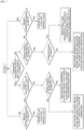
- the construction machine may further include: an operating device configured to perform various operations of the traveling body and the rotating body; a swing sensor configured to detect a turning operation of the rotating body; and a safety shut-off valve configured to cut off pilot pressure to control the operation of the work device, wherein the control device selects one of the plurality of lighting or flashing patterns to be expressed by the multifunctional auxiliary brake light according to an information signal provided by one or more of the operating device, the swing sensor, and the safety shut-off valve and operation information of the work device.
- the control device may turn on the multifunctional auxiliary brake light as an auxiliary brake light.
- the control device may recognize as a work ready state and turn on the multifunctional auxiliary brake light to warn that work starts.
- the control device may recognize as a working state and cause the multifunctional auxiliary brake light to be flashed to warn that work is in progress.
- control device may turn on the multifunctional auxiliary brake light as an auxiliary brake light.
- the control device may recognize as a working state and flash the multifunctional auxiliary brake light to worn that work is in progress.
- the control device may repeatedly and sequentially turn on the multifunctional auxiliary brake light in a turning direction to indicate the turning direction.
- the construction machine may give a warning to surroundings by classifying various work states through a multifunctional auxiliary brake light.
- Embodiments of the present disclosure are presented as idealized embodiments of the present disclosure. As a result, various modifications of the drawings are expected. The disclosed embodiments are not limited to the specific forms in certain regions illustrated in the drawings, and for example, include modifications of such forms by manufacturing.
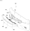
- FIGS. 1 to 6 a construction machine 101 according to a first embodiment of the present disclosure is described with reference to FIGS. 1 to 6 .
- the construction machine 101 may be an excavator.
- the construction machine 101 may include a traveling body for traveling and a rotating body rotatably installed in an upper portion of the traveling body.
- the traveling body may support the rotating body and causes the construction machine 101 to travel through the traveling device using power generated by an engine.
- the traveling body may be a wheel-type traveling body including a plurality of driving wheels.
- the rotating body may rotate on the traveling body to set a working direction.
- the rotating body may include a frame, a driving room installed in the frame, and various work devices 300 (shown in FIG. 6 ).
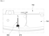
- the rotating body may include an engine room 750 (shown in FIG. 2 ).
- the work device 300 may include a boom, an arm, and a bucket. Also, the work device may include a boom cylinder for controlling movement of the boom, an arm cylinder for controlling movement of the arm, and a bucket cylinder for controlling movement of the bucket.
- a plurality of attachments including a tilt rotator, a shovel, a breaker, a vibrator, and a hammer, instead of a bucket, may be selectively mounted depending on the type of work.
- the construction machine 101 may include a rear member 700, a support plate 600, a multifunctional auxiliary brake light 800, a cable 850, and a control device 500.
- the construction machine 101 may further include an insulating stopper 870 and a protective plate 900.
- the construction machine 101 may further include an operating device 400, a swing sensor 450, a safety shut-off valve 470, and a control device 500.
- the rear member 700 is installed at the rear of the engine room 750 provided in the rotating body. Also, in the first embodiment of the present disclosure, the rear member 700 may be a counterweight. These counterweight may be installed to increase a workable critical load of the construction machine 101.
- the counterweight may have a curved shape
- the multifunctional auxiliary brake light 800 to be described below may have a shape corresponding to the curved shape of the counterweight and may be coupled to the counterweight.
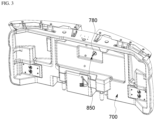
- the rear member 700 may be formed with a through-hole 780 communicating with the engine room 750.
- the through-hole 780 penetrates through one side of the rear member 700 facing the engine room 750 and the other side opposite the one side.
- the support plate 600 may be attached to one side of the rear member 700 opposite to the other side of the engine room 750.
- the support plate 600 detachably couples the multifunctional auxiliary brake light 800 to be described below to the rear member 700.
- the support plate 600 may include a plurality of fastening holes.
- a hole corresponding to the through-hole 780 of the rear member 700 may be formed in the support plate 600.
- the support plate 600 may be formed in a structure that seals the engine room 750.
- the support plate 600 may be used together with the insulating stopper 870.
- the insulating stopper 870 may block the through-hole 780 while the cable 850 penetrates through the through-hole 780.
- the insulating stopper 870 may prevent heat from the engine room 750 from being transmitted to the multifunctional auxiliary brake light 800 through the through-hole 780 of the rear member 700 and causing thermal damage to the multifunctional auxiliary brake light 800.
- the insulating stopper 870 may be formed of rubber.
- the multifunctional auxiliary brake light 800 may be coupled to the support plate 600 and may extend in a left-right direction to express a selected one of a plurality of lighting or flashing patterns.
- the multifunctional auxiliary brake light 800 may be turned on or flash or turn on repeatedly and sequentially in one direction.
- the left-right direction refers to a horizontal direction when the construction machine 101 is viewed from the rear.
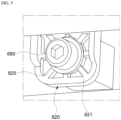
- the multifunctional auxiliary brake light 800 may include a lamp portion 810 and a coupling portion 820 fastened to the support plate 600 by a bolt 680 to couple the lamp portion 810 to the support plate 600.
- the coupling portion 820 may include a bolt fastening hole 821 through which the bolt 680 is fastened and a plurality of reinforcing ribs 825 formed radially around the bolt fastening hole 821.
- the coupling portion 820 may be provided in plurality along the circumference of the lamp portion 80.
- the coupling portion 820 prepared in this manner improves the vibration resistance characteristics and strength to protect the lamp portion 810 from vibrations since vibrations are severe in terms of the construction machine 101 and is designed to distribute stress by increasing a contact area with the support plate 600.
- the cable 850 may be connected to the multifunctional auxiliary brake light 800 through the through-hole 780 of the rear member 700.
- the cable 850 may supply a control signal and electricity to the multifunctional auxiliary brake light 800.
- the control device 500 may be connected to the cable 850 and may control the multifunctional auxiliary brake light 800. At this time, as shown in FIG. 6 , the control device 500 may selectively control one of the plurality of lighting or flashing patterns to be expressed by the multifunctional auxiliary brake light 800 depending on an information signal provided by one or more of the operating device 400, the swing sensor 450, and the safety shut-off valve 470 and work information of the work device 300.
- control device 500 may be installed in the engine room 750 or on one side of the rear member 700 facing the engine room 750.
- the installation location of the control device 500 is not limited to the above.
- the protective plate 900 may be coupled to the support plate 600 and surround the edge of the multifunctional auxiliary brake light 800 to protect the multifunctional auxiliary brake light 800.
- the protective plate 900 may be buried in the counterweight, which is the rear member 700, to be coupled to the counterweight.
- the operating device 400 may be installed in a driving compartment of the rotating body to perform various operations of the traveling body and the rotating body.
- the operating device 400 may include a joystick, a control panel, a pedal, as well as various operating levers and switches.
- the swing sensor 450 may detect a rotating operation of the rotating body.
- the safety shut-off valve 470 may block pilot pressure for controlling the operation of the work device 500 according to a user's operation.
- control device 500 selects one of the plurality of lighting or flashing patterns to be expressed by the multifunctional auxiliary brake light 800 according to the information signal provided by one or more of the operating device 400, the swing sensor 450, and the safety shut-off valve 450 described above and the work information of the work device 300.
- the control device 500 may receive an additional information signal from one or more of a key box, a gear box, and a brake device and use the same to control the multifunctional auxiliary brake light 800.
- the safety shut-off valve 470 may operate, and a brake operation signal is input, the control device 500 may turn on the multifunctional auxiliary brake light 800 as an auxiliary brake light. That is, when the brake device operates, the multifunctional auxiliary brake light 800 may be turned on.
- the control device 500 may recognize it as a work ready state and turn on the multifunctional auxiliary brake light 800 to warn that work starts. That is, the control device 500 may turn on the multifunctional auxiliary brake light 800 to alert workers who work around the construction machine 101 to warn that the construction machine 101 will soon start to work.
- the control device 500 recognizes it as a working state and causes the multifunctional auxiliary brake light 800 to be flashed to warn that work is in progress. That is, the multifunctional auxiliary brake light 800 may be flashed to warn workers who work around the construction machine 101 that the construction machine 101 is currently working.
- the control device 500 may turn on the multifunctional auxiliary brake light 800 as an auxiliary brake light. That is, when the brake device operates, the multifunctional auxiliary brake light 800 may be turned on.
- the control device 500 may recognize it as a working state and may flash the multifunctional auxiliary brake light 800 to worn that work is in progress. That is, the control device 500 may flash the multifunctional auxiliary brake light 800 to warn workers who work around the construction machine 101 that the construction machine 101 is currently working. In this case, the control device 500 may recognize a work state during traveling and warn that work is in progress.
- the control device 500 may repeatedly and sequentially turn on the multifunctional auxiliary brake light 800 in a turning direction to indicate the turning direction. For example, when the rotating body of the construction machine 101 turns left, the multifunctional auxiliary brake light 800 may be turned on sequentially from left to right in a longitudinal direction. Conversely, when the rotating body of the construction machine 101 turns right, the multifunctional auxiliary brake light 800 may be turned on sequentially from right to left in the longitudinal direction.
- the construction machine 101 may effectively give a warning to surroundings by classifying various work states through the multifunctional auxiliary brake light 800.
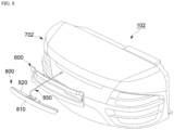
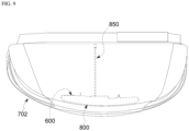
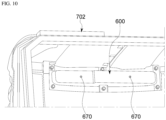
- FIGS. 8 to 10 a second embodiment of the present disclosure will be described with reference to FIGS. 8 to 10 .
- the rear member 700 may be an engine room cover.
- the support plate 600 may be formed to surround the entire multifunctional auxiliary brake light 800.
- the protective plate 900 used in the first embodiment may be omitted.
- the support plate 600 when the support plate 600 is coupled to the engine cover, which is the rear member 700, the support plate 600 may be guided to be coupled to the rear member 700 in a correct position by using a guide pin 670 to ensure positional alignment of the multifunctional auxiliary brake light 800 surrounded by the support plate 600.
- the method of controlling the multifunctional auxiliary brake light 800 is the same as the first embodiment described above.
- a construction machine 102 according to the second embodiment of the present disclosure may also effectively give a warning to surroundings by classifying various work states through the multifunctional auxiliary brake light 800.
- Embodiments of the present disclosure may be used to provide a construction machine capable of giving a warning to surroundings by classifying various work states through a multifunctional auxiliary brake light.
Landscapes
- Engineering & Computer Science (AREA)
- Mining & Mineral Resources (AREA)
- Civil Engineering (AREA)
- General Engineering & Computer Science (AREA)
- Structural Engineering (AREA)
- Mechanical Engineering (AREA)
- Physics & Mathematics (AREA)
- Electromagnetism (AREA)
- General Physics & Mathematics (AREA)
- Lighting Device Outwards From Vehicle And Optical Signal (AREA)
- Component Parts Of Construction Machinery (AREA)
Applications Claiming Priority (2)
| Application Number | Priority Date | Filing Date | Title |
|---|---|---|---|
| KR1020210153165A KR20230067262A (ko) | 2021-11-09 | 2021-11-09 | 건설 기계 |
| PCT/KR2022/017412 WO2023085718A1 (fr) | 2021-11-09 | 2022-11-08 | Engin de chantier |
Publications (2)
| Publication Number | Publication Date |
|---|---|
| EP4424931A1 true EP4424931A1 (fr) | 2024-09-04 |
| EP4424931A4 EP4424931A4 (fr) | 2025-11-12 |
Family
ID=86336062
Family Applications (1)
| Application Number | Title | Priority Date | Filing Date |
|---|---|---|---|
| EP22893138.2A Pending EP4424931A4 (fr) | 2021-11-09 | 2022-11-08 | Engin de chantier |
Country Status (5)
| Country | Link |
|---|---|
| US (1) | US20240416828A1 (fr) |
| EP (1) | EP4424931A4 (fr) |
| KR (1) | KR20230067262A (fr) |
| CN (1) | CN118215771A (fr) |
| WO (1) | WO2023085718A1 (fr) |
Family Cites Families (7)
| Publication number | Priority date | Publication date | Assignee | Title |
|---|---|---|---|---|
| JP2777534B2 (ja) * | 1993-10-01 | 1998-07-16 | 建設省関東地方建設局長 | 建設機械の監視装置 |
| JPH10183687A (ja) * | 1996-12-25 | 1998-07-14 | Kanzaki Kokyukoki Mfg Co Ltd | 建設機械のカウンターウエイト |
| JP3939874B2 (ja) * | 1999-02-19 | 2007-07-04 | 日立建機株式会社 | 作業車両のリア部品の取付構造 |
| JP2002227252A (ja) * | 2001-02-02 | 2002-08-14 | Hitachi Constr Mach Co Ltd | 建設機械の走行警告装置 |
| JP2002327469A (ja) * | 2001-05-02 | 2002-11-15 | Komatsu Ltd | 建設機械における周囲安全装置 |
| JP2006161306A (ja) * | 2004-12-03 | 2006-06-22 | Hitachi Constr Mach Co Ltd | 建設機械の配線引き回し構造 |
| KR20110072071A (ko) * | 2009-12-22 | 2011-06-29 | 볼보 컨스트럭션 이큅먼트 에이비 | 건설기계의 비콘램프 제어장치 및 그 방법 |
-
2021
- 2021-11-09 KR KR1020210153165A patent/KR20230067262A/ko active Pending
-
2022
- 2022-11-08 US US18/708,647 patent/US20240416828A1/en active Pending
- 2022-11-08 WO PCT/KR2022/017412 patent/WO2023085718A1/fr not_active Ceased
- 2022-11-08 EP EP22893138.2A patent/EP4424931A4/fr active Pending
- 2022-11-08 CN CN202280074718.8A patent/CN118215771A/zh active Pending
Also Published As
| Publication number | Publication date |
|---|---|
| EP4424931A4 (fr) | 2025-11-12 |
| WO2023085718A1 (fr) | 2023-05-19 |
| US20240416828A1 (en) | 2024-12-19 |
| KR20230067262A (ko) | 2023-05-16 |
| CN118215771A (zh) | 2024-06-18 |
Similar Documents
| Publication | Publication Date | Title |
|---|---|---|
| JP5004834B2 (ja) | 作業機械 | |
| CN104271847B (zh) | 建筑机械的显示装置以及建筑机械 | |
| US11518318B2 (en) | Shovel | |
| CN112638696A (zh) | 电动式作业机械 | |
| EP4502302A1 (fr) | Engin de chantier | |
| KR102841525B1 (ko) | 건설 기계 | |
| WO2021101214A1 (fr) | Procédé et système de commande pour machine de construction | |
| EP4424931A1 (fr) | Engin de chantier | |
| JP2020159045A (ja) | 建設機械 | |
| CN116917582B (zh) | 工程机械 | |
| KR20170024295A (ko) | 작업기계 | |
| JPH0533359A (ja) | 全旋回型の小型バツクホウ | |
| KR101735107B1 (ko) | 틸팅캐빈의 제어 시스템 | |
| JPH09217383A (ja) | 遠隔操作式建設機械 | |
| EP4512965A1 (fr) | Engin de chantier | |
| KR102898015B1 (ko) | 건설 기계 및 이의 구동 방법 | |
| JP7157091B2 (ja) | 作業用車両 | |
| JP2024143378A (ja) | 建設機械の運転支援システム | |
| EP0955415A1 (fr) | Pelle hydraulique | |
| KR100193943B1 (ko) | 슬래그 제거장치 | |
| JP2025044550A (ja) | 建設機械 | |
| JP3415598B2 (ja) | 圧気発生手段と溶接装置を備えた油圧ショベル | |
| EP3974585A1 (fr) | Engin de chantier | |
| JP2024060135A (ja) | 作業機械 | |
| CN116981815A (zh) | 电动式作业机械 |
Legal Events
| Date | Code | Title | Description |
|---|---|---|---|
| STAA | Information on the status of an ep patent application or granted ep patent |
Free format text: STATUS: THE INTERNATIONAL PUBLICATION HAS BEEN MADE |
|
| PUAI | Public reference made under article 153(3) epc to a published international application that has entered the european phase |
Free format text: ORIGINAL CODE: 0009012 |
|
| STAA | Information on the status of an ep patent application or granted ep patent |
Free format text: STATUS: REQUEST FOR EXAMINATION WAS MADE |
|
| 17P | Request for examination filed |
Effective date: 20240529 |
|
| AK | Designated contracting states |
Kind code of ref document: A1 Designated state(s): AL AT BE BG CH CY CZ DE DK EE ES FI FR GB GR HR HU IE IS IT LI LT LU LV MC ME MK MT NL NO PL PT RO RS SE SI SK SM TR |
|
| P01 | Opt-out of the competence of the unified patent court (upc) registered |
Free format text: CASE NUMBER: APP_50591/2024 Effective date: 20240906 |
|
| DAV | Request for validation of the european patent (deleted) | ||
| DAX | Request for extension of the european patent (deleted) | ||
| A4 | Supplementary search report drawn up and despatched |
Effective date: 20251013 |
|
| RIC1 | Information provided on ipc code assigned before grant |
Ipc: E02F 9/24 20060101AFI20251007BHEP Ipc: E02F 9/08 20060101ALI20251007BHEP Ipc: E02F 9/12 20060101ALI20251007BHEP Ipc: E02F 9/22 20060101ALI20251007BHEP Ipc: G08B 3/10 20060101ALI20251007BHEP Ipc: B60Q 1/44 20060101ALI20251007BHEP |