EP4424955A1 - Verriegelungsvorrichtung für eine schliessanlage einer gebäudeöffnung - Google Patents
Verriegelungsvorrichtung für eine schliessanlage einer gebäudeöffnung Download PDFInfo
- Publication number
- EP4424955A1 EP4424955A1 EP24157436.7A EP24157436A EP4424955A1 EP 4424955 A1 EP4424955 A1 EP 4424955A1 EP 24157436 A EP24157436 A EP 24157436A EP 4424955 A1 EP4424955 A1 EP 4424955A1
- Authority
- EP
- European Patent Office
- Prior art keywords
- locking
- hooking
- hand
- locking device
- attachment
- Prior art date
- Legal status (The legal status is an assumption and is not a legal conclusion. Google has not performed a legal analysis and makes no representation as to the accuracy of the status listed.)
- Pending
Links
Images






Classifications
-
- E—FIXED CONSTRUCTIONS
- E05—LOCKS; KEYS; WINDOW OR DOOR FITTINGS; SAFES
- E05B—LOCKS; ACCESSORIES THEREFOR; HANDCUFFS
- E05B65/00—Locks or fastenings for special use
- E05B65/08—Locks or fastenings for special use for sliding wings
- E05B65/087—Locks or fastenings for special use for sliding wings the bolts sliding parallel to the wings
-
- E—FIXED CONSTRUCTIONS
- E05—LOCKS; KEYS; WINDOW OR DOOR FITTINGS; SAFES
- E05C—BOLTS OR FASTENING DEVICES FOR WINGS, SPECIALLY FOR DOORS OR WINDOWS
- E05C9/00—Arrangements of simultaneously actuated bolts or other securing devices at well-separated positions on the same wing
- E05C9/02—Arrangements of simultaneously actuated bolts or other securing devices at well-separated positions on the same wing with one sliding bar for fastening when moved in one direction and unfastening when moved in opposite direction; with two sliding bars moved in the same direction when fastening or unfastening
-
- E—FIXED CONSTRUCTIONS
- E05—LOCKS; KEYS; WINDOW OR DOOR FITTINGS; SAFES
- E05C—BOLTS OR FASTENING DEVICES FOR WINGS, SPECIALLY FOR DOORS OR WINDOWS
- E05C9/00—Arrangements of simultaneously actuated bolts or other securing devices at well-separated positions on the same wing
- E05C9/18—Details of fastening means or of fixed retaining means for the ends of bars
- E05C9/1808—Keepers
-
- E—FIXED CONSTRUCTIONS
- E05—LOCKS; KEYS; WINDOW OR DOOR FITTINGS; SAFES
- E05C—BOLTS OR FASTENING DEVICES FOR WINGS, SPECIALLY FOR DOORS OR WINDOWS
- E05C9/00—Arrangements of simultaneously actuated bolts or other securing devices at well-separated positions on the same wing
- E05C9/18—Details of fastening means or of fixed retaining means for the ends of bars
- E05C9/1825—Fastening means
- E05C9/1833—Fastening means performing sliding movements
- E05C9/185—Fastening means performing sliding movements parallel with actuating bar
-
- E—FIXED CONSTRUCTIONS
- E05—LOCKS; KEYS; WINDOW OR DOOR FITTINGS; SAFES
- E05B—LOCKS; ACCESSORIES THEREFOR; HANDCUFFS
- E05B65/00—Locks or fastenings for special use
- E05B65/08—Locks or fastenings for special use for sliding wings
- E05B65/0811—Locks or fastenings for special use for sliding wings the bolts pivoting about an axis perpendicular to the wings
-
- E—FIXED CONSTRUCTIONS
- E05—LOCKS; KEYS; WINDOW OR DOOR FITTINGS; SAFES
- E05B—LOCKS; ACCESSORIES THEREFOR; HANDCUFFS
- E05B65/00—Locks or fastenings for special use
- E05B65/08—Locks or fastenings for special use for sliding wings
- E05B65/0858—Locks or fastenings for special use for sliding wings comprising simultaneously pivoting double hook-like locking members
-
- E—FIXED CONSTRUCTIONS
- E05—LOCKS; KEYS; WINDOW OR DOOR FITTINGS; SAFES
- E05C—BOLTS OR FASTENING DEVICES FOR WINGS, SPECIALLY FOR DOORS OR WINDOWS
- E05C9/00—Arrangements of simultaneously actuated bolts or other securing devices at well-separated positions on the same wing
- E05C9/18—Details of fastening means or of fixed retaining means for the ends of bars
- E05C9/1825—Fastening means
- E05C9/1875—Fastening means performing pivoting movements
Definitions
- the invention relates to a locking device which is intended to equip a closing installation which is configured to close an opening which a construction comprises.
- This invention relates to the field of building hardware, more particularly to the field of locking devices which are configured to ensure the locking, in the closed position, of an installation for closing an opening that a construction has.
- These locking devices are, more particularly, configured to equip such a closing installation, more particularly an opening and a fixed frame that such a closing installation comprises.
- Locking devices which comprise, on the one hand, a strike plate which equips the frame with a closing installation and, on the other hand, a locking system, which equips the opening with this closing installation, and which is actuated by a locking rod usually controlled by a handle or the like.
- a locking system usually comprises a locking member which adopts the form of a roller or a hook, and which is movable between, on the one hand, an inactive locking position in which this locking member does not cooperate with the strike plate and, on the other hand, an active locking position in which this locking member cooperates with the strike plate.
- a locking member has a reduced contact surface with the strike plate which limits the mechanical strength of the locking device, in particular in the event of an attempted break-in.
- a break-in force exerted on the closing installation and/or on the locking device may result in the locking member moving from an active locking position to an inactive locking position. As a result, these locking devices cannot guarantee a high level of security against break-in.
- the present invention aims to remedy the drawbacks of the locking devices of the state of the art.
- the invention relates to a locking device for a system for closing an opening in a building.
- a locking device comprises a locking strike which is configured to equip a frame, respectively an opening frame, of the closing installation.
- a locking device also comprises a locking system, which is configured to equip the opening frame, respectively the frame, of the closing installation, and which is configured to cooperate with the locking strike.
- This locking system comprises, on the one hand, a housing which is configured to equip the opening, respectively the frame, on the other hand, at least one locking rod, which is configured to equip the opening, respectively the frame, and which is movable relative to the housing, on the other hand also, at least two hooking means, which are movable relative to the housing, and which are configured to adopt an inactive position of hooking of said at least two hooking means with the locking striker and an active position of hooking of said at least two hooking means with the locking striker, on the other hand again, displacement mounting means which are configured to mount said at least two hooking means in displacement relative to the housing, this between the inactive hooking position and the active position of hooking of said at least two hooking means with the locking striker and, on the other hand also, displacement drive means which are configured to drive in displacement said at least two hooking means, as the case may be, in the direction of the inactive hooking position or in the direction of the active hooking position, this under the impulse of the movement of the locking rod.
- This locking device is characterized in that the means for driving said at least two attachment means in movement comprise, on the one hand, means for driving said at least two attachment means in translation, on the other hand, primary means for driving said at least two attachment means in translation, which comprise primary means for driving said at least one of said at least two attachment means in translation in a first translation direction, and, on the other hand, secondary means for driving said at least one other of said at least two attachment means in translation in a second translation direction, which is the opposite of the first translation direction.
- said at least two attachment means each adopt the shape of a attachment hook and each comprise a attachment member while the attachment members of said at least two attachment means are oriented towards each other and/or face each other.
- moving mounting means are configured to mount said at least two means of translational attachment relative to the housing, this in the same direction which is parallel to the direction of movement of the locking rod.
- the movement drive means are configured to drive said at least two attachment means in movement towards and away from at least one of said at least two attachment means from at least one other of said at least two attachment means.
- the locking device comprises reinforcing means which are configured to reinforce the attachment of at least one of said at least two attachment means on the locking strike, this in the active attachment position and in the event of break-in stress exerted on the locking device and/or on the closing installation.
- the locking device comprises means for holding at least one of said at least two attachment means in the inactive attachment position of said at least two attachment means.
- the locking device comprises means for fixing the locking system on the opening leaf, respectively on the frame.
- These fixing means comprise, on the one hand, at least one plate which is configured to bear on the rear of an internal wall that the opening leaf, respectively the frame, comprises, and/or to come to be positioned inside a rebate that the opening leaf, respectively the frame, comprises, and, on the other hand, at least one fixing member which is configured to cooperate with said at least one plate as well as with a headplate that the locking system and/or the closing installation comprises.
- the locking device of the invention comprises at least two hooking means which can adopt an active hooking position with the locking striker.
- the presence of these at least two hooking means makes it possible to multiply the points of contact between the locking striker and the locking system in the active hooking position, which advantageously makes it possible to increase the mechanical strength of the locking device, in particular in the event of an attempted break-in, and thus to improve the locking.
- the improvement of this locking then allows the locking device of the invention to access high-level anti-break-in security categories, in particular level RC2.
- the movement drive means are configured to drive said at least two hooking means in movement towards and away from at least one of said at least two hooking means from at least one other of said at least two hooking means.
- These hooking means then operate in opposition of movement so that, when at least one of these attachment means is requested to be unhooked from the latch (in particular in the context of an attempted break-in), at least one other of these attachment means reinforces its attachment to the latch. This results in an improvement in locking.
- the locking device comprises reinforcing means that are configured to reinforce the attachment of said at least two attachment means to the locking striker.
- Such reinforcing means advantageously allow, in the event of a break-in stress exerted on the locking device, to bring at least one of said at least two attachment means into an active reinforced attachment position (going beyond the active attachment position).
- Such reinforcing means are configured so that only an action on the locking rod allows said at least two attachment means to be brought into their inactive attachment position.
- the locking device comprises means for fixing the locking system to the opening leaf, respectively to the frame.
- Such fixing means advantageously make it possible to reinforce the connection between the locking system and the opening leaf, respectively the frame, of the closing installation.
- the present invention relates to the field of building hardware, more particularly the field of locking devices which are configured to ensure the locking, in the closed position, of an installation for closing an opening of a construction.
- Such a closing installation can consist of a window, a French window, a bay window or other.
- Such a closing installation I comprises, on the one hand, at least one frame D which is made integral with the masonry, which delimits said opening, and which the construction comprises and, on the other hand, at least one opening O which is movable relative to the frame D, this between an opening position ( figure 1 ) and a closing position.
- Such an opening O may be of the hinged or (and preferably) sliding type.
- Such an opening O comprises, on the one hand, a glazing and, on the other hand, a plurality of profiles, which are assembled to define a frame intended to internally receive the glazing, and at least some (or even all) of which have at least one internal wall as well as a rebate (more particularly a glass rebate) for receiving said glazing.
- the invention then relates to a locking device 1 for such an installation for closing an opening in a building.
- Such a locking device 1 comprises a locking strike 2 which is configured to equip the frame D, respectively the opening O, which the closing installation I comprises.
- Such a locking device 1 also comprises a locking system 3 which is configured to equip the opening O, respectively the frame D, with the closing installation I.
- a locking system 3 is, more particularly, configured to be installed, at least in part, inside a housing that this opening O, respectively this frame D comprises, more particularly inside a housing that one of the profiles that this opening O, respectively this frame D comprises.
- Such a locking system 3 is also configured to cooperate with the locking striker 2.
- Said locking system 3 comprises a housing 4 which is configured to equip the opening O, respectively the frame D.
- this housing 4 is, more particularly, configured to be installed, at least in part, inside the aforementioned housing that this opening O, respectively this frame D comprises, more particularly inside the aforementioned housing that one of the profiles that this opening O, respectively this frame D comprises.
- Said locking system 3 also comprises at least one locking rod 5, which is configured to equip the opening O, respectively the frame D, and which is movable (more particularly in translation) relative to the housing 4 as well as relative to the opening O, respectively to the frame D.
- This locking rod 5 is configured to cooperate (directly or indirectly) with a control member, more particularly in the form of a handle or the like, which equips the opening O, respectively the frame D.
- Said locking system 3 also comprises at least two attachment means (6; 6'), each of which adopts the shape of an attachment hook, and each of which comprises an attachment member (60; 60').
- the attachment members (60; 60') of said at least two attachment means (6; 6') are oriented towards one (60; 60') of the other (60'; 60) and/or face each other.
- said at least two attachment means (6; 6') each comprise, on the one hand, an internal part which extends inside the housing 4 and, on the other hand, an external part, which extends outside the housing 4, and which comprises said attachment member (60'; 60).
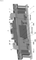
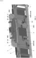
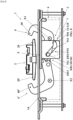
- Said at least two hooking means (6; 6') are movable relative to the housing 4 and are configured to adopt, on the one hand, an inactive position of hooking of said at least two hooking means (6; 6') with the locking latch 2 ( figures 3 , 5 And 8 ) in which said at least two hooking members (6; 6') (more particularly the hooking members 60; 60') are not hooked to the locking latch 2.
- said at least two hooking means (6; 6') are configured to adopt an active position of hooking of said at least two hooking means (6; 6') with the locking latch 2 ( figures 2 , 4 , 6 And 9 ) in which said at least two hooking members (6; 6') (more particularly the hooking members 60; 60') are hooked to the locking latch 2.
- this locking strike 2 then comprises at least two complementary attachment means (20; 20), on the one hand, which are configured to be fixed relative to the frame D, respectively relative to the opening O, and, on the other hand, which are each configured to cooperate with one (6; 6') of said at least two attachment means (6; 6'), plus particularly with one (60; 60') of the hooking members (60; 60') comprised in said at least two hooking means (6; 6'), this in the active hooking position.
- Said locking system 3 further comprises displacement mounting means 7 which are configured to mount said at least two attachment means (6; 6') in displacement relative to the housing 4, this between the inactive attachment position and the active attachment position of said at least two attachment means (6; 6') with the locking striker 2.
- the displacement mounting means 7 are configured to mount said at least two attachment means (6; 6') in translation relative to the housing 4, each in a direction (more particularly in the same direction) which is parallel to the direction of displacement (more particularly to the direction of translation) of the locking rod 5.
- the displacement mounting means 7 are configured to mount, relative to the housing 4, on the one hand, at least one 6 of said at least two attachment means (6; 6') in rotation about a first axis of rotation X1 and, on the other hand, at least one other 6' of said at least two attachment means (6; 6') in rotation about a second axis of rotation X2 which is parallel to the first axis of rotation X1.
- first axis of rotation X1 and the second axis of rotation X2 are perpendicular to the direction of movement of the locking rod 5.
- said locking system 3 also comprises movement drive means 8 which are configured to drive said at least two hooking means (6; 6') in movement, as the case may be, in the direction of the inactive hooking position (more particularly from the active hooking position) or in the direction of the active hooking position (more particularly from the inactive hooking position), this under the impulse of the movement of the locking rod 5.
- Such movement drive means 8 are configured to drive said at least two attachment means (6; 6') in movement relative to the housing 4, each in a direction (more particularly in the same direction) which is parallel to the direction of movement of the locking rod 5.
- the movement drive means 8 are configured to drive said at least two attachment means (6; 6') in movement towards and away from at least one (6; 6') of said at least two attachment means (6; 6') from at least one other (6'; 6) of said at least two attachment means (6; 6').
- displacement drive means 8 are configured to drive said at least two attachment means (6; 6'), this simultaneously.
- the movement drive means 8 of said at least two attachment means (6; 6') comprise, on the one hand, primary movement drive means 9 which are configured to move at least one 6 of said at least two attachment means (6; 6') in a first direction of movement and, on the other hand, secondary movement drive means 10 which are configured to move at least one other 6' of said at least two attachment means (6; 6') in a second direction of movement which is the opposite of the first direction of movement.
- the displacement drive means 8 of said at least two attachment means (6; 6') comprise (or are constituted by) translation drive means 80 of said at least two attachment means (6; 6').
- Such translation drive means 80 are, then, more particularly, configured to drive said at least two attachment means (6; 6') in translation relative to the housing 4, each in a direction (more particularly in the same direction) which is parallel to the translation direction of the locking rod 5.
- the primary displacement drive means 9 comprise (or are constituted by) primary translation drive means 90 which are configured to drive in translation (more particularly in a translation direction at least parallel to the direction of displacement/translation of the locking rod 5) at least one 6 of said at least two attachment means (6; 6') in a first translation direction and, on the other hand, the secondary displacement drive means 10 comprise (or are constituted by) secondary translation drive means 100 which are configured to drive in translation (more particularly in a translation direction at least parallel to the direction of displacement/translation of the locking rod 5) at least another 6' of said at least two attachment means (6; 6') in a second translation direction which is opposite to the first translation direction.
- the primary translational drive means 90 comprise (or are constituted by) the locking rod 5, which is integral in movement with at least one 6 of said at least two attachment means (6; 6'), and which is configured to drive said at least one 6 of said at least two attachment means (6; 6') in the first direction of translation.
- these comprise a transmission member 1000, which is mounted in rotation relative to the housing 4 and around an axis of rotation X3 (more particularly perpendicular to the direction of movement of the locking rod 5), which comprises a first part 1001 which cooperates with the locking rod 5 as well as a second part 1002, which is opposite the first part 1001 relative to the axis of rotation X3, and which cooperates with said at least one other 6' of said at least two attachment means (6'; 6).
- a transmission member 1000 which is mounted in rotation relative to the housing 4 and around an axis of rotation X3 (more particularly perpendicular to the direction of movement of the locking rod 5), which comprises a first part 1001 which cooperates with the locking rod 5 as well as a second part 1002, which is opposite the first part 1001 relative to the axis of rotation X3, and which cooperates with said at least one other 6' of said at least two attachment means (6'; 6).
- said transmission member 1000 can adopt the form of a toothed wheel
- the first part 1001 of this toothed wheel comprises teeth which cooperate with the locking rod 5 (more particularly with notches, openings or a rack that this locking rod 5 comprises)
- the second part 1002 of this toothed wheel comprises teeth which cooperate with said at least one other 6' of said at least two attachment means (6; 6'), more particularly with notches, openings or a rack that said at least one other 6' of said at least two attachment means (6; 6') comprises.
- said transmission member 1000 can adopt the form of a lever
- the first part 1001 of this lever comprises a first free end which cooperates with the locking rod 5 (more particularly which is integral in movement with this locking rod 5 and/or which passes through a slot which this locking rod 5 comprises)
- the second part 1002 of this lever comprises a second free end which cooperates with said (more particularly which is integral in movement with said) at least one other 6' of said at least two attachment means (6'; 6).
- the second free end may comprise means for securing in movement (more particularly at least one relief, in particular in the form of a stud or a pin secured to - or even attached to - the second free end of the lever) and, on the other hand, said at least one other 6' of said at least two attachment means (6; 6') comprises complementary means for securing in movement (more particularly at least one relief, in particular in the form of a housing, a ramp or a cutout) which cooperate with the means for securing in movement.
- the displacement drive means 8 of said at least two attachment means (6; 6') comprise (or are constituted by) rotation drive means 81 of said at least two attachment means (6; 6').
- the primary movement drive means 9 comprise (or are constituted by) primary rotation drive means 91 which are configured to drive in rotation (more particularly around the first axis of rotation X1) at least one 6 of said at least two attachment means (6; 6') in a first direction (more particularly clockwise, respectively counterclockwise) of rotation and, on the other hand, the secondary movement drive means 10 comprise (or are constituted by) secondary rotation drive means 101 which are configured to drive in rotation (more particularly around the second axis of rotation X2) at least another 6' of said at least two attachment means (6; 6') in a second direction (more particularly counterclockwise, respectively clockwise) of rotation which is the opposite of the first direction (more particularly clockwise, respectively counterclockwise) of rotation.
- the primary rotation drive means 91 comprise, on the one hand, at least one easel 910, which is mounted so as to be movable in movement (more particularly in translation) in a determined direction (more particularly parallel to the direction of translational movement of the locking rod 5) inside the housing 4 and relative to the housing 4, which is integral in movement (more particularly in translation) with the locking rod 5 (more particularly which is driven by this locking rod 5), and which comprises at least one guide light 911 which extends in a direction making an acute angle with the direction of movement (more particularly in translation) of the easel 910 and, on the other hand, at least one guide member 912 (more particularly in the form of a stud), which comprises said at least one 6 of said at least two attachment means (6; 6'), and which is guided inside said at least one guide light 911.
- easel 910 which is mounted so as to be movable in movement (more particularly in translation) in a determined direction (more particularly parallel to the direction of translational movement of the locking rod 5) inside the housing 4 and relative to the housing 4, which is integral
- these can, according to a first illustrated embodiment Figures 5 to 7 , comprising, on the one hand, at least one easel 1010 (more particularly constituted by said easel 910 described above) which is mounted in a movably movable manner in displacement (more particularly in translation) in a determined direction (more particularly parallel to the direction of displacement in translation of the locking rod 5) inside the housing 4 and relative to the housing 4, which is integral in displacement (more particularly in translation) of the locking rod 5, and which comprises at least one guide light 1011 (more particularly distinct from the guide light 911 described above) which extends in a direction making an acute angle with the direction of movement (more particularly in translation) of the easel 1010 and, on the other hand, at least one guide member 1012 (more particularly in the form of a stud and/or distinct from the guide member 912 mentioned above), which comprises said at least one other 6' of said at least two attachment means (6; 6'), and which is guided inside said at least one guide light 1011.
- easel 1010 more particularly constituted by said easel 910 described
- the secondary rotation drive means 101 may comprise transmission means 1013 which are configured to transmit a rotational movement between said at least one 6 of said at least two attachment means (6; 6') and said at least one other 6' of said at least two attachment means (6; 6').
- such transmission means 1013 may comprise, on the one hand, a first gear which comprises said at least one 6 of said at least two attachment means (6; 6') and, on the other hand, a second gear, which comprises said at least one other 6' of said at least two attachment means (6; 6'), and which cooperates with said first gear.
- the locking device 1 comprises reinforcing means 11 which are configured to reinforce the attachment of at least one (6; 6') of said at least two attachment means (6; 6') on the locking strike 2, this in the active attachment position of said at least two attachment means (6; 6') and in the event of break-in stress exerted on the locking device 1 and/or on the closing installation I.
- the reinforcing means 11 comprise at least one housing 110, which the easel 910 comprises (more particularly which the primary rotation drive means 91 comprise), which extends from (more particularly in the extension) of said at least one guide light 911 (which the easel 910 comprises) as well as in a direction which forms a non-zero angle (preferably open or obtuse) with the direction in which said at least one guide light 911 extends (direction which then also forms a non-zero angle with the direction of movement of the locking rod 5), and inside which said guide member 912 is housed, this in the active position of attachment of said at least two attachment means (6; 6') and in the event of break-in stress exerted on the locking device 1 and/or on the closing installation I, more particularly of a traction exerted perpendicular to the direction of movement of the locking rod 5 on at least one (6; 6') of said at least two attachment means (6; 6').
- such reinforcing means 11 may also comprise at least one other housing (not shown), which the easel 1010 comprises (more particularly which the secondary rotation drive means 101 comprise), which extends from (more particularly in the extension) of said at least one guide light 1011 (which the easel 1010 comprises) as well as in a direction which forms a non-zero angle (preferably open or obtuse) with the direction in which said at least one guide light 1011 extends (direction which then also forms a non-zero angle with the direction of movement of the locking rod 5), and inside which said guide member 1012 is housed, this in the active position of attachment of said at least two attachment means (6; 6') and in the event of break-in stress exerted on the locking device 1 and/or on the closing installation I, plus particularly of a traction exerted perpendicular to the direction of movement of the locking rod 5 on at least one (6; 6') of said at least two attachment means (6; 6').
- the locking device 1 comprises holding means 12 which are configured to hold at least one (6; 6') of said at least two hooking means (6; 6') in the inactive hooking position of said at least two hooking means (6; 6').
- these holding means 12 comprise at least one housing 120, which the easel 910 comprises (more particularly which the primary rotation drive means 91 comprise), which extends from (more particularly in the extension) of said at least one guide light 911 (which the easel 910 comprises) as well as in a direction which forms a non-zero angle (preferably open or obtuse) with the direction in which said at least one guide light 911 extends (direction which then also forms a non-zero angle with the direction of movement of the locking rod 5), and inside which said guide member 912 is housed, this in the inactive position of attachment of said at least two attachment means (6; 6').
- these holding means 12 may also comprise at least one other housing 121, which the easel 1010 comprises (more particularly which the secondary rotation drive means 101 comprise), which extends from (more particularly in the extension) of said at least one guide light 1011 (which the easel 1010 comprises) as well as in a direction which forms a non-zero angle (preferably open or obtuse) with the direction in which said at least one guide light 1011 extends (direction which then also forms a non-zero angle with the direction of movement of the locking rod 5), and inside which said guide member 1012 is housed, this in the inactive position of attachment of said at least two attachment means (6; 6').
- said at least one housing 110 of the reinforcement means 11 extends from (more particularly in the extension) of one end presented by said at least one guide light 911 (which the primary rotation drive means 91 comprise) while said at least one housing 120 of the holding means 12 extends from (more particularly in the extension) of another end (more particularly from an opposite end) presented by said at least one guide light 911 (which the primary rotation drive means 91 comprise).
- said at least one other housing of the reinforcement means 11 extends from (more particularly in the extension) of one end that said at least one guide light 1011 has (that the secondary rotation drive means 101 comprise) while said at least one housing 121 of the holding means 12 extends from (more particularly in the extension) of another end (more particularly from an opposite end) that said at least one guide light 1011 has (that the secondary rotation drive means 101 comprise).
- the locking device 1 comprises fixing means 13 which are configured to fix the locking system 3 on the opening O, respectively on the frame D.
- These fixing means 13 comprise, on the one hand, at least one plate 130 which is configured to be positioned inside a rebate (more particularly a glass rebate) that the opening O (respectively the frame D) comprises and/or to rest on the rear of an internal wall, that the opening O (respectively the frame D) comprises, and which is, then, interposed between the housing 4 of the locking system 3 and the plate 130.
- a rebate more particularly a glass rebate
- these fixing means 13 comprise at least one fixing member 131 (more particularly in the form of a screw, a tie rod or the like) which is configured to cooperate with said at least one plate 130 (more particularly by being screwed through this plate 130) as well as with a head 14 (more particularly by passing through this head 14) which the locking device 1 (more particularly the locking system 3) and/or the closing installation I comprise.
- fixing means 13 may be of an additional type and be configured to supplement fixing means of the prior art which comprise a screw (or the like), which passes through the head 14, and which cooperates directly with an internal wall comprised by the opening O (respectively the frame D).
- such fixing means 13 can also be envisaged to integrate locking devices 1 which have characteristics different from those described above, or even only part of these characteristics.
- such fixing means 13 can integrate a locking device (not shown) which comprises, on the one hand, a locking strike which is configured to equip a frame (respectively an opening) with a closing installation and, on the other hand, a locking system, which is configured to equip the opening (respectively the frame) with the closing installation, and which is configured to cooperate with the locking strike.
- This locking system can then also comprise a housing which is configured to equip the opening (respectively the frame), as well as at least one attachment means, which is movable relative to the housing, and which is configured to adopt an inactive position for attachment of said at least one attachment means with the locking strike and an active position for attachment of said at least one attachment means with the locking strike.
- This locking system may also comprise displacement mounting means (which may be different from those described above) which are configured to mount said at least one attachment means in displacement relative to the housing, this between the inactive attachment position and the active attachment position of said at least one attachment means with the locking striker, or even also displacement drive means (which may be different from those described above) which are configured to drive said at least one attachment means in displacement, as the case may be, in the direction of the inactive attachment position or in the direction of the active attachment position, or even also a locking rod.
- displacement mounting means which may be different from those described above
- displacement drive means which are configured to drive said at least one attachment means in displacement relative to the housing, this between the inactive attachment position and the active attachment position of said at least one attachment means with the locking striker
- displacement drive means which may be different from those described above
Landscapes
- Engineering & Computer Science (AREA)
- Mechanical Engineering (AREA)
- Lock And Its Accessories (AREA)
- Clamps And Clips (AREA)
Applications Claiming Priority (1)
| Application Number | Priority Date | Filing Date | Title |
|---|---|---|---|
| FR2301848A FR3146157B1 (fr) | 2023-02-28 | 2023-02-28 | Dispositif de verrouillage pour une installation de fermeture d’une ouverture d’une construction |
Publications (1)
| Publication Number | Publication Date |
|---|---|
| EP4424955A1 true EP4424955A1 (de) | 2024-09-04 |
Family
ID=86469248
Family Applications (1)
| Application Number | Title | Priority Date | Filing Date |
|---|---|---|---|
| EP24157436.7A Pending EP4424955A1 (de) | 2023-02-28 | 2024-02-13 | Verriegelungsvorrichtung für eine schliessanlage einer gebäudeöffnung |
Country Status (2)
| Country | Link |
|---|---|
| EP (1) | EP4424955A1 (de) |
| FR (1) | FR3146157B1 (de) |
Citations (3)
| Publication number | Priority date | Publication date | Assignee | Title |
|---|---|---|---|---|
| GB2298451A (en) | 1995-03-03 | 1996-09-04 | Securistyle Ltd | Multiple bolt actuating mechanism |
| EP1243729A2 (de) | 2001-03-20 | 2002-09-25 | Roto Frank Eisenwarenfabrik Aktiengesellschaft | Schubstangenbetätigbarer Verschluss für Fenster, Türen oder dergleichen |
| GB2503954A (en) * | 2012-07-14 | 2014-01-15 | Vita Corp Co Ltd | Driving device for simultaneously moving locking bolts |
Family Cites Families (4)
| Publication number | Priority date | Publication date | Assignee | Title |
|---|---|---|---|---|
| GB8727627D0 (en) * | 1987-11-25 | 1987-12-31 | Goodwin W J & Son Ltd | Improvements in or relating to locks |
| GB2298449B (en) * | 1995-03-03 | 1998-09-16 | Securistyle Ltd | A vent locking assembly |
| IT201800006134A1 (it) * | 2018-06-08 | 2019-12-08 | Serratura | |
| FR3102496B1 (fr) * | 2019-10-29 | 2021-11-12 | La Croisee D S | Dispositif de verrouillage d’un ouvrant coulissant |
-
2023
- 2023-02-28 FR FR2301848A patent/FR3146157B1/fr active Active
-
2024
- 2024-02-13 EP EP24157436.7A patent/EP4424955A1/de active Pending
Patent Citations (3)
| Publication number | Priority date | Publication date | Assignee | Title |
|---|---|---|---|---|
| GB2298451A (en) | 1995-03-03 | 1996-09-04 | Securistyle Ltd | Multiple bolt actuating mechanism |
| EP1243729A2 (de) | 2001-03-20 | 2002-09-25 | Roto Frank Eisenwarenfabrik Aktiengesellschaft | Schubstangenbetätigbarer Verschluss für Fenster, Türen oder dergleichen |
| GB2503954A (en) * | 2012-07-14 | 2014-01-15 | Vita Corp Co Ltd | Driving device for simultaneously moving locking bolts |
Also Published As
| Publication number | Publication date |
|---|---|
| FR3146157B1 (fr) | 2025-06-13 |
| FR3146157A1 (fr) | 2024-08-30 |
Similar Documents
| Publication | Publication Date | Title |
|---|---|---|
| EP0943768B1 (de) | Rückstellvorrichtung des Betätigungsorgans für ein Schlossgehäuse, Treibstangenschloss oder dergleichen | |
| BE1020832A3 (fr) | Dispositif de commande de verrouillage pour vantail. | |
| EP0207869B1 (de) | Einlassespagnolette mit zwei Treibstangen und Zentralriegel | |
| FR3146157A1 (fr) | Dispositif de verrouillage pour une installation de fermeture d’une ouverture d’une construction | |
| EP0882861B1 (de) | Verriegelungsvorrichtung für einen Schiebeflügel | |
| EP0246989B1 (de) | Sicherheitstür, insbesondere für Kästen, Fächer und Geldschränke | |
| EP1564354B1 (de) | Steuerungs- und Verriegelungssystem, insbesondere für Treibstangenverschluss, zum Öffnen und Schliessen einer Tür | |
| EP0891465B1 (de) | Treibstange oder treibstangenschloss, insbesondere mit mehrpunktverriegelung | |
| FR2529937A1 (fr) | Dispositif de fermeture a pene profile enveloppant rotatif et a gache rentrante | |
| FR2765261A1 (fr) | Ferrure de verrouillage pour ouvrant coulissant et dispositif anti-effraction pour une telle ferrure | |
| EP0837208B1 (de) | Treibstangenbremsevorrichtung und Schiebeflügel mit einer solchen Vorrichtung | |
| EP1241307B1 (de) | Feststeller für Tür, Fenster dgl. mit treibstangenverschlussartigen Beschlag | |
| EP4050182B1 (de) | Vorrichtung zur steuerung eines verriegelungs-/entriegelungsmechanismus eines öffnungsflügels | |
| EP2253787B1 (de) | Schließvorrichtung mit Basküleverschluss | |
| EP3098370B1 (de) | Motorisierte schliessvorrichtung, die ein automatisches ver- und entriegelungssystem eines klappladens umfasst | |
| EP1878862B1 (de) | Verriegelungseinrichtung für einen Flügel | |
| EP2317046A1 (de) | Treibstangengetriebe oder Treibstangenverschluss | |
| EP1245767A1 (de) | Schliessblech für eine Tür oder ein Fenster oder dergleichen | |
| EP0391750A1 (de) | Türschloss mit mehreren Riegeln, welches in einem aus zwei ineinandergreifenden Profilen geformten Gehäuse eingebettet ist | |
| FR3159621A1 (fr) | Dispositif de commande d’une crémone d’un vantail oscillo-battant | |
| FR2821876A1 (fr) | Entrebailleur pour porte, fenetre ou similaire equipe d'une ferrure de verrouillage du type cremone | |
| EP1273745A2 (de) | Antihebungsvorrichtung für einen verschiebbaren Flügel einer Tür, eines Fensters od. dgl | |
| FR2757558A1 (fr) | Dispositif de blocage pour une portiere de vehicule automobile, et vehicule automobile comportant un tel dispositif | |
| FR2883022A1 (fr) | Dispositif empechant la fermeture inopinee d'une porte | |
| FR2928398A1 (fr) | Dispositif de verrouillage pour cremone ou cremone-serrure |
Legal Events
| Date | Code | Title | Description |
|---|---|---|---|
| PUAI | Public reference made under article 153(3) epc to a published international application that has entered the european phase |
Free format text: ORIGINAL CODE: 0009012 |
|
| STAA | Information on the status of an ep patent application or granted ep patent |
Free format text: STATUS: THE APPLICATION HAS BEEN PUBLISHED |
|
| AK | Designated contracting states |
Kind code of ref document: A1 Designated state(s): AL AT BE BG CH CY CZ DE DK EE ES FI FR GB GR HR HU IE IS IT LI LT LU LV MC ME MK MT NL NO PL PT RO RS SE SI SK SM TR |
|
| STAA | Information on the status of an ep patent application or granted ep patent |
Free format text: STATUS: REQUEST FOR EXAMINATION WAS MADE |
|
| 17P | Request for examination filed |
Effective date: 20250303 |
|
| P01 | Opt-out of the competence of the unified patent court (upc) registered |
Free format text: CASE NUMBER: APP_30809/2025 Effective date: 20250626 |