EP4424965A1 - Gebäudeöffnungsabdeckung mit einem griff mit einer benutzerinteraktionssensoranordnung - Google Patents
Gebäudeöffnungsabdeckung mit einem griff mit einer benutzerinteraktionssensoranordnung Download PDFInfo
- Publication number
- EP4424965A1 EP4424965A1 EP23159064.7A EP23159064A EP4424965A1 EP 4424965 A1 EP4424965 A1 EP 4424965A1 EP 23159064 A EP23159064 A EP 23159064A EP 4424965 A1 EP4424965 A1 EP 4424965A1
- Authority
- EP
- European Patent Office
- Prior art keywords
- gripping part
- movable unit
- force
- handle
- user interaction
- Prior art date
- Legal status (The legal status is an assumption and is not a legal conclusion. Google has not performed a legal analysis and makes no representation as to the accuracy of the status listed.)
- Withdrawn
Links
Images




Classifications
-
- E—FIXED CONSTRUCTIONS
- E05—LOCKS; KEYS; WINDOW OR DOOR FITTINGS; SAFES
- E05F—DEVICES FOR MOVING WINGS INTO OPEN OR CLOSED POSITION; CHECKS FOR WINGS; WING FITTINGS NOT OTHERWISE PROVIDED FOR, CONCERNED WITH THE FUNCTIONING OF THE WING
- E05F15/00—Power-operated mechanisms for wings
- E05F15/60—Power-operated mechanisms for wings using electrical actuators
- E05F15/603—Power-operated mechanisms for wings using electrical actuators using rotary electromotors
- E05F15/611—Power-operated mechanisms for wings using electrical actuators using rotary electromotors for swinging wings
- E05F15/616—Power-operated mechanisms for wings using electrical actuators using rotary electromotors for swinging wings operated by push-pull mechanisms
- E05F15/619—Power-operated mechanisms for wings using electrical actuators using rotary electromotors for swinging wings operated by push-pull mechanisms using flexible or rigid rack-and-pinion arrangements
-
- E—FIXED CONSTRUCTIONS
- E05—LOCKS; KEYS; WINDOW OR DOOR FITTINGS; SAFES
- E05Y—INDEXING SCHEME ASSOCIATED WITH SUBCLASSES E05D AND E05F, RELATING TO CONSTRUCTION ELEMENTS, ELECTRIC CONTROL, POWER SUPPLY, POWER SIGNAL OR TRANSMISSION, USER INTERFACES, MOUNTING OR COUPLING, DETAILS, ACCESSORIES, AUXILIARY OPERATIONS NOT OTHERWISE PROVIDED FOR, APPLICATION THEREOF
- E05Y2201/00—Constructional elements; Accessories therefor
- E05Y2201/20—Brakes; Disengaging means; Holders; Stops; Valves; Accessories therefor
- E05Y2201/214—Disengaging means
-
- E—FIXED CONSTRUCTIONS
- E05—LOCKS; KEYS; WINDOW OR DOOR FITTINGS; SAFES
- E05Y—INDEXING SCHEME ASSOCIATED WITH SUBCLASSES E05D AND E05F, RELATING TO CONSTRUCTION ELEMENTS, ELECTRIC CONTROL, POWER SUPPLY, POWER SIGNAL OR TRANSMISSION, USER INTERFACES, MOUNTING OR COUPLING, DETAILS, ACCESSORIES, AUXILIARY OPERATIONS NOT OTHERWISE PROVIDED FOR, APPLICATION THEREOF
- E05Y2201/00—Constructional elements; Accessories therefor
- E05Y2201/20—Brakes; Disengaging means; Holders; Stops; Valves; Accessories therefor
- E05Y2201/218—Holders
- E05Y2201/22—Locks
-
- E—FIXED CONSTRUCTIONS
- E05—LOCKS; KEYS; WINDOW OR DOOR FITTINGS; SAFES
- E05Y—INDEXING SCHEME ASSOCIATED WITH SUBCLASSES E05D AND E05F, RELATING TO CONSTRUCTION ELEMENTS, ELECTRIC CONTROL, POWER SUPPLY, POWER SIGNAL OR TRANSMISSION, USER INTERFACES, MOUNTING OR COUPLING, DETAILS, ACCESSORIES, AUXILIARY OPERATIONS NOT OTHERWISE PROVIDED FOR, APPLICATION THEREOF
- E05Y2201/00—Constructional elements; Accessories therefor
- E05Y2201/20—Brakes; Disengaging means; Holders; Stops; Valves; Accessories therefor
- E05Y2201/23—Actuation thereof
- E05Y2201/232—Actuation thereof by automatically acting means
- E05Y2201/234—Actuation thereof by automatically acting means direction dependent
-
- E—FIXED CONSTRUCTIONS
- E05—LOCKS; KEYS; WINDOW OR DOOR FITTINGS; SAFES
- E05Y—INDEXING SCHEME ASSOCIATED WITH SUBCLASSES E05D AND E05F, RELATING TO CONSTRUCTION ELEMENTS, ELECTRIC CONTROL, POWER SUPPLY, POWER SIGNAL OR TRANSMISSION, USER INTERFACES, MOUNTING OR COUPLING, DETAILS, ACCESSORIES, AUXILIARY OPERATIONS NOT OTHERWISE PROVIDED FOR, APPLICATION THEREOF
- E05Y2201/00—Constructional elements; Accessories therefor
- E05Y2201/20—Brakes; Disengaging means; Holders; Stops; Valves; Accessories therefor
- E05Y2201/23—Actuation thereof
- E05Y2201/244—Actuation thereof by manual operation
-
- E—FIXED CONSTRUCTIONS
- E05—LOCKS; KEYS; WINDOW OR DOOR FITTINGS; SAFES
- E05Y—INDEXING SCHEME ASSOCIATED WITH SUBCLASSES E05D AND E05F, RELATING TO CONSTRUCTION ELEMENTS, ELECTRIC CONTROL, POWER SUPPLY, POWER SIGNAL OR TRANSMISSION, USER INTERFACES, MOUNTING OR COUPLING, DETAILS, ACCESSORIES, AUXILIARY OPERATIONS NOT OTHERWISE PROVIDED FOR, APPLICATION THEREOF
- E05Y2201/00—Constructional elements; Accessories therefor
- E05Y2201/60—Suspension or transmission members; Accessories therefor
- E05Y2201/622—Suspension or transmission members elements
- E05Y2201/676—Transmission of human force
- E05Y2201/68—Handles, cranks
-
- E—FIXED CONSTRUCTIONS
- E05—LOCKS; KEYS; WINDOW OR DOOR FITTINGS; SAFES
- E05Y—INDEXING SCHEME ASSOCIATED WITH SUBCLASSES E05D AND E05F, RELATING TO CONSTRUCTION ELEMENTS, ELECTRIC CONTROL, POWER SUPPLY, POWER SIGNAL OR TRANSMISSION, USER INTERFACES, MOUNTING OR COUPLING, DETAILS, ACCESSORIES, AUXILIARY OPERATIONS NOT OTHERWISE PROVIDED FOR, APPLICATION THEREOF
- E05Y2400/00—Electronic control; Electrical power; Power supply; Power or signal transmission; User interfaces
- E05Y2400/10—Electronic control
- E05Y2400/30—Electronic control of motors
- E05Y2400/3013—Electronic control of motors during manual wing operation
-
- E—FIXED CONSTRUCTIONS
- E05—LOCKS; KEYS; WINDOW OR DOOR FITTINGS; SAFES
- E05Y—INDEXING SCHEME ASSOCIATED WITH SUBCLASSES E05D AND E05F, RELATING TO CONSTRUCTION ELEMENTS, ELECTRIC CONTROL, POWER SUPPLY, POWER SIGNAL OR TRANSMISSION, USER INTERFACES, MOUNTING OR COUPLING, DETAILS, ACCESSORIES, AUXILIARY OPERATIONS NOT OTHERWISE PROVIDED FOR, APPLICATION THEREOF
- E05Y2400/00—Electronic control; Electrical power; Power supply; Power or signal transmission; User interfaces
- E05Y2400/10—Electronic control
- E05Y2400/30—Electronic control of motors
- E05Y2400/3013—Electronic control of motors during manual wing operation
- E05Y2400/3015—Power assistance
-
- E—FIXED CONSTRUCTIONS
- E05—LOCKS; KEYS; WINDOW OR DOOR FITTINGS; SAFES
- E05Y—INDEXING SCHEME ASSOCIATED WITH SUBCLASSES E05D AND E05F, RELATING TO CONSTRUCTION ELEMENTS, ELECTRIC CONTROL, POWER SUPPLY, POWER SIGNAL OR TRANSMISSION, USER INTERFACES, MOUNTING OR COUPLING, DETAILS, ACCESSORIES, AUXILIARY OPERATIONS NOT OTHERWISE PROVIDED FOR, APPLICATION THEREOF
- E05Y2400/00—Electronic control; Electrical power; Power supply; Power or signal transmission; User interfaces
- E05Y2400/10—Electronic control
- E05Y2400/44—Sensors not directly associated with the wing movement
-
- E—FIXED CONSTRUCTIONS
- E05—LOCKS; KEYS; WINDOW OR DOOR FITTINGS; SAFES
- E05Y—INDEXING SCHEME ASSOCIATED WITH SUBCLASSES E05D AND E05F, RELATING TO CONSTRUCTION ELEMENTS, ELECTRIC CONTROL, POWER SUPPLY, POWER SIGNAL OR TRANSMISSION, USER INTERFACES, MOUNTING OR COUPLING, DETAILS, ACCESSORIES, AUXILIARY OPERATIONS NOT OTHERWISE PROVIDED FOR, APPLICATION THEREOF
- E05Y2400/00—Electronic control; Electrical power; Power supply; Power or signal transmission; User interfaces
- E05Y2400/80—User interfaces
- E05Y2400/85—User input means
- E05Y2400/856—Actuation thereof
- E05Y2400/858—Actuation thereof by body parts, e.g. by feet
- E05Y2400/86—Actuation thereof by body parts, e.g. by feet by hand
-
- E—FIXED CONSTRUCTIONS
- E05—LOCKS; KEYS; WINDOW OR DOOR FITTINGS; SAFES
- E05Y—INDEXING SCHEME ASSOCIATED WITH SUBCLASSES E05D AND E05F, RELATING TO CONSTRUCTION ELEMENTS, ELECTRIC CONTROL, POWER SUPPLY, POWER SIGNAL OR TRANSMISSION, USER INTERFACES, MOUNTING OR COUPLING, DETAILS, ACCESSORIES, AUXILIARY OPERATIONS NOT OTHERWISE PROVIDED FOR, APPLICATION THEREOF
- E05Y2900/00—Application of doors, windows, wings or fittings thereof
- E05Y2900/10—Application of doors, windows, wings or fittings thereof for buildings or parts thereof
- E05Y2900/13—Type of wing
- E05Y2900/148—Windows
-
- E—FIXED CONSTRUCTIONS
- E05—LOCKS; KEYS; WINDOW OR DOOR FITTINGS; SAFES
- E05Y—INDEXING SCHEME ASSOCIATED WITH SUBCLASSES E05D AND E05F, RELATING TO CONSTRUCTION ELEMENTS, ELECTRIC CONTROL, POWER SUPPLY, POWER SIGNAL OR TRANSMISSION, USER INTERFACES, MOUNTING OR COUPLING, DETAILS, ACCESSORIES, AUXILIARY OPERATIONS NOT OTHERWISE PROVIDED FOR, APPLICATION THEREOF
- E05Y2900/00—Application of doors, windows, wings or fittings thereof
- E05Y2900/10—Application of doors, windows, wings or fittings thereof for buildings or parts thereof
- E05Y2900/13—Type of wing
- E05Y2900/148—Windows
- E05Y2900/152—Roof windows
Definitions
- the present disclosure relates to a building aperture cover. Moreover, the present disclosure relates to a method of controlling an actuator arrangement of a building aperture cover.
- Various building aperture cover types such as e.g. windows, comprise a glass unit that enable sunlight passing into the building when the building aperture cover is installed to cover a building aperture in an outer wall or in a roof structure of the building.
- These windows may comprise a handle that is configured to operated by human hand in order to open or close a movable unit, such as a sash, of the window, to provide ventilation, where the movable unit comprises the glass unit.
- the window may also comprise an actuator arrangement comprising an actuator configured to move the movable unit between an open or closed position.
- An actuator arrangement configured to open and close the movable unit of a building aperture cover may e.g. be remote controlled and/or controlled by a central controller.
- US 2007/0170729 discloses a handle.
- the handle comprises control elements and/or sensors and a handle part which can be displaced into various positions of the handle which correspond to different operational positions.
- the handle is connected to electromagnetic or electromechanical locking elements. This solution may e.g. be considered less user friendly.
- the present disclosure relates to a building aperture cover comprising a fixation frame and a movable unit.
- the movable unit is connected to the fixation frame by means of a hinge arrangement so that the movable unit is configured to be moved relative to the fixation frame between a closed unit position and an open unit position.
- the movable unit comprises an insulated glass unit.
- the building aperture cover comprises an electric actuator arrangement configured to provide the movement of the movable unit between the closed unit position and the open unit position.
- the building aperture cover comprises a handle.
- the handle is attached to a part of the movable unit, and the handle comprises a gripping part configured to be grasped by human hand.
- the building aperture cover comprises a control system comprising one or more hardware processors.
- the handle comprises a user interaction sensor arrangement configured to detect physical user interactions applied at the gripping part, and provide sensor data based thereon.
- the control system is configured to receive and process the sensor data.
- the control system is configured to provide first control output based on the processing of the sensor data, if the sensor data comprises information indicating that a first user interaction comprising a first activation force in a first force direction is applied to the gripping part.
- the control system is configured to provide second control output based on said processing of the sensor data if the sensor data comprises information indicating that a second user interaction comprising a second activation force in a second force direction is applied to the gripping part.
- the electric actuator arrangement is configured to apply an opening force to the movable unit if the first control output is provided, and the actuator arrangement is configured to apply a closing force to the movable unit if the second control output is provided.
- the above solution may e.g. provide an opening/closing solution for a building aperture cover that may be intuitive to use by a human user, and may hence help to provide a solution where user operation mistakes are reduced. For example guests may often struggle with windows because most window control solutions are un-intuitive.
- the solution may provide that human users may be relieved from needing to manually providing a substantial lifting force onto the movable unit in order to open or close the window as the actuator arrangement provides the opening force and/or closing force dependent on the detected activation force.
- the present solution may provide advantages when compared to wireless, separate, hand held remote controls as these may e.g. be displaced and lost or be less intuitive because it is not clear which remote control opens which window or the remote control existence may be unknown to a human user (e.g. a visitor in the building).
- Physical user interactions may enable an intuitive and user friendly control.
- Providing that the user interaction sensor arrangement is arranged in the handle, and that forces are detected directly in/at the handle arrangement may e.g. help to provide a solution that is easy to install. Additionally or alternatively, it may help to reduce the risk of erroneously registering forces that should not induce the actuator to move the movable unit. Additionally or alternatively, it may enable an intuitive and user friendly control.
- a building aperture such as a building aperture cover according to embodiments of the present disclosure, such as a door or a window, may comprise a movable unit that is configured to be opened and closed.
- air can travel through the building aperture, for example between a fixation frame and the movable unit.
- closed unit position air may be prevented from traveling through the building aperture, or the amount of air that may be allowed to travel through the building aperture may be significantly reduced when compared to the open unit position.
- a door or a window may comprise a ventilation solution that may allow a reduced amount of air to travel through the ventilation solution of the aperture cover although the movable unit is arranged in the closed position.
- the building aperture cover comprises a locking system.
- This locking system is configured to be arranged in a locked state and an unlocked state, respectively.
- the movable unit is configured to be movable towards the open position from the closed position when the locking system is in the unlocked state.
- the movable unit is configured to be in a locked unit state in the closed unit position by means of the locking system when the locking system is in the locked state.
- the handle such as the gripping part, is configured to be operated by human hand so as to control in which of said states the locking system is arranged.
- the locking system may e.g. help to provide a more burglary safe solution and/or a solution that may be safe during extreme weather conditions.
- Said control/manipulation of the locking system may comprise e.g. comprise controlling the gripping part, such as moving the gripping part relative to the movable unit, e.g. by rotation of the gripping part around a rotation axis, so as to shift the state of the locking system between the locked state and an unlocked state.
- the movable unit In the locked unit state, the movable unit is directly or indirectly prevented by the locking system from moving towards the open position, this is the case when the movable unit is in the closed position and the locking system is in the locked state.
- the handle such as the gripping part may be configured to be moved relative to the movable unit, such as by means of the actuator system and/or human hand so as to control the in which state the locking system is arranged.
- the gripping part is configured to be moved, such as by displacement and/or rotation, relative to the movable unit between a first gripping part position and a second gripping part position, respectively.
- the locking system is configured to be arranged in the locked state when the gripping part is arranged in the first gripping part position.
- the locking system is configured to be arranged in the unlocked state when the gripping part is arranged in the second gripping part position.
- This may e.g. help to provide a user friendly and/or intuitive solution. Additionally or alternatively, it may enable providing a mechanically simple and/or cost efficient solution.
- the handle such as the gripping part, may in embodiments of the present disclosure be directly or indirectly coupled to the locking system so as to be configured to switch the locking system between the locked state and the unlocked state in response to a movement of the gripping part relative to the movable unit.
- the gripping part may be configured to be moved, such as by displacement and/or rotation, relative to the movable unit between a first gripping part position and a second gripping part position by human hand, so that a disengagement of a lock between the fixation frame and the movable unit is provided and/or so that a disengagement of an electric actuator arrangement lock connection between the fixation frame and the movable unit is provided.
- This may e.g. help to provide a safe and/or user friendly, such as intuitive, solution.
- the gripping part may be configured to be moved, such as by displacement and/or rotation, relative to the movable unit between a first gripping part position and a second gripping part position by human hand, so that a disengagement of a lock between the fixation frame and the movable unit is provided.
- the gripping part is configured to be moved, such as by displacement and/or rotation, relative to the movable unit between a first gripping part position and a second gripping part position by human hand, so that a disengagement of an electric actuator arrangement lock connection between the fixation frame and the movable unit is provided.
- the gripping part may be configured to be moved, such as by displacement and/or rotation, relative to the movable unit between a first gripping part position and a second gripping part position by human hand, so that a disengagement of a lock between the fixation frame and the movable unit is provided, and so that a disengagement of an electric actuator arrangement connection between the fixation frame and the movable unit is provided.
- the gripping part is configured to be placed in two positions relative to the movable unit, when the movable unit is in the closed unit position. These two positions may comprise a first gripping part position where the electric actuator arrangement is engaged so as to move the movable unit during closing and/or opening, and a second gripping part position where the actuator is disengaged so as to not move, such as unable to close and/or open, the movable unit.
- the handle may be configured to have two gripping part positions comprising a first gripping part position where a lock is engaged and the movable unit is therefore unable to move, and a second gripping part position where a lock is released/disengaged and the movable unit is therefore configured to move.
- the handle such as the gripping part
- the handle may be directly or indirectly mechanically coupled to the locking system so as to be configured to mechanically switch the locking system between the locked state and the unlocked state by movement of the gripping part relative to the movable unit.
- This may e.g. help to provide a reliable and/or cost efficient control of the locking system. It may additionally or alternatively help to provide a mechanically simple locking system solution.
- the handle such as the gripping part
- the handle may be electrically, such as wirelessly, coupled to the locking system so as to switch the locking system between the locked state and the unlocked state.
- the gripping part may be substantially unmovable relative to the handle, and alone the forces provided at the handle may control the opening and closing of the movable unit.
- a locking system may be provided, and in that case, the locking system may be e.g. magnetically, electrically, and/or wirelessly controlled and/or the like, e.g. in response to detecting the forces.
- operation of the actuator arrangement may be configured to be omitted despite the first and/or second activation force being provided onto the gripping part, when the gripping part is arranged in a first gripping part position or when the gripping part in a second gripping part position.
- This may e.g. be relevant in situations where the actuator is decoupled from the movable unit when the handle is arranged in the second gripping part position. For example in response to moving the gripping part from the first gripping part position to the second gripping part position. In this case it may not be desired that the actuator arrangement will be activated by pulling or pushing forces provided by human hand on the gripping part, as the hand may here be used for manually opening and closing the movable unit independently of the actuator.
- a handle state sensor may be arranged at the handle in order to detect/determine the handle position, for example by detecting directly or indirectly whether the gripping part is in the first or second gripping part position (relative to the movable unit).
- the handle/gripping part is detected by the handle state sensor to be in the second gripping part position, said omission of operating the actuator arrangement may be provided.
- actuator operation may be accepted when an activation force is provided at the gripping part.
- the first and/or second control output may be provided in response to an activation force.
- a unit position sensor may in embodiments of the present disclosure be provided in order to determine the position of the movable unit. For example, said omission of operation of the actuator arrangement may occur if the gripping part is detected to be in the first gripping part position and if the movable unit is detected to be in a closed position. If, on the other hand, the movable unit is detected to be in an open position, the closing force and/or opening force provided by the actuator arrangement may still be allowed to be provided.
- operation of the actuator arrangement may be configured to be omitted despite the first and/or second activation force being provided onto the gripping part, when the gripping part is arranged in the first gripping part position.
- This may e.g. be relevant in a solution where the handle is of a configuration where a latch or the like of the locking system mechanically connected/coupled to the position of the gripping part in a way so that that the gripping part needs to be arranged in the second gripping part position to enable a movement of the movable unit from a closed position to an open position.
- the actuator system provides the opening force when the gripping part is in the first position, as the locking system will here be in the locked position, and the locking system will hence will prevent opening of the movable unit.
- the actuator arrangement may be configured to provide the opening force in response to the first activation force being provided onto the gripping part while the gripping part is arranged in the first gripping part position.
- This may e.g. enable automatic control of the movable unit, for example without first needing manual control of the handle.
- the actuator may be able to control/switch the locking system state. In further embodiments of the present disclosure, this may be enabled even though the gripping part is arranged in the first gripping part position. Hence, when the handle is in a first gripping part position, the locking system may be arranged in the locked state, but may still be switched to the unlocked state by means of the actuator arrangement. Hence, for example, the actuator arrangement may, when the first activation force is applied at the handle, in response to the activation force unlock the locking system, i.e. control, such as move, it to the unlocked state. In some embodiments, this may be obtained by the actuator being configured to directly or indirectly move the gripping part relative to the movable unit.
- the user interaction sensor arrangement is configured to detect an opening first user interaction, such as an activation force, applied at a first surface of the gripping part, and is moreover configured to detect a closing second user interaction, such as an activation force, applied at a second opposite surface of the gripping part. This may e.g. provide an intuitive control solution.
- the user interaction sensor arrangement comprises two or more sensors provided to detect user interactions at two opposite surfaces of the handle.
- a first of the sensors may here, in embodiments, be configured to detect an opening first user interaction, such as an activation force, applied at a first surface of the gripping part.
- a second opposite sensor may be configured to detect a closing second user interaction, such as an activation force, applied at a second opposite surface of the gripping part. This may e.g. help provide a reliable and/or cost efficient sensor solution for detection of user interactions at the gripping part.
- said control system may be configured to refrain from providing said control output if the user interaction sensor arrangement detects an opening first user interaction, such as an activation force, applied at a first surface of the gripping part, and moreover detects a closing second user interaction, such as an activation force, applied at a second opposite surface of the gripping part. If both user interactions related to both opening and closing of the movable unit are detected simultaneously (e.g. in some embodiments, if a human hand grasps around the gripping part), this may indicate a manual control of the handle and/or movable unit, and hence, the actuator may refrain from activating the actuator.
- an opening first user interaction such as an activation force
- a closing second user interaction such as an activation force
- said control system may be configured to refrain from providing said control output if the first sensor detects a opening first user interaction and the second opposite sensor simultaneously detects a closing second user interaction. If the first and second sensors are actiavated simultaneously (e.g. in some embodiments, if a human hand grasps around the gripping part), this may indicate a manual control of the handle and/or movable unit, and hence, the actuator may refrain from activating the actuator.
- the locking system may be configured to be switched from a locked state to an unlocked state in response to the first control output. In some further embodiments, this may be provided by means of the opening force provided by the actuator arrangement. For example, it may be provided by means of an actuator of the actuator arrangement moving the gripping part from the first gripping part position to the second gripping part position.
- the actuator and lock may be sequential hereby understood such that part of the actuator displacement controls the lock state between locked or unlocked while another part of the actuator displacement moves the movable unit e.g. the window.
- two separate actuators may be used to control the lock state and movement of the movable unit.
- the first activation force may be a force comprising a force vector component in a handle movement direction, where said handle movement direction is the movement direction of the handle that will occur when a movement of the movable unit from the closed unit position towards the open unit position is initiated by the actuator arrangement.
- the second activation force may be a force comprising a force vector component in a handle movement direction, where said handle movement direction is the movement direction of the handle that will occur when a movement of the movable unit from the open unit position towards the closed unit position is initiated by the actuator arrangement.
- This may e.g. provide a "natural mapping" solution which is intuitive to the user.
- the first activation force is designed to be in the direction of the handle movement when the movable unit initially starts to move towards an open position from the closed position, this may represent an intuitive and inherently expected force direction to be applied in order to obtain opening of the movable unit.
- the second activation force is a force in the movement direction of the handle when the movable unit moves to the closed position.
- the first and second activation forces may in embodiments of the present disclosure be forces that are configured to initiate opening and closing, respectively, of the movable unit.
- the force vector component is the major force vector component.
- the majority of the opening and closing force direction must match the actual movement of the movable unit.
- the first and second activation forces may in embodiments of the present disclosure be substantially oppositely directed.
- control system may be configured to provide a control output configured to induce the actuator unit to stop providing the opening force if the second activation force is provided by a human user at the gripping part while the actuator arrangement provides the opening force.
- control system may be configured to provide a control signal so as to induce the actuator arrangement to provide the closing force if a consecutive second activation force provided by a human user at the gripping part is detected.
- the building aperture cover may comprise comprises a locking system configured to be wirelessly controlled in response to the first user interaction, so as to enter an unlocked state.
- the locking system may be wirelessly controlled, such as electrically and/or magnetically controlled, by means of a lock controller, wherein the lock controller is configured to switch the locking system from a locked state to an unlocked state, for example prior to the opening force being applied by the actuator arrangement.
- the locking system may in some embodiments, e.g. be or comprise an electrically controlled, such as an electromechanically and/or electromagnetically controlled, locking system.
- the first control output may be configured to induce the lock controller to switch the locking system from the locked state to an unlocked state while the gripping part is arranged in the first gripping part position.
- This may e.g. enable a user friendly and intuitive solution.
- the first control output may be configured to induce the lock controller to switch the locking system from the locked state to an unlocked state while the gripping part is arranged in the first gripping part position.
- the switching of the locking system may be configured to be provided prior to the actuator arrangement provide the opening force, and/or by means of the opening force.
- the actuator arrangement may be configured to move the movable unit from the closed unit position towards the open unit position by means of said opening force and/or
- the actuator arrangement may be configured to move the movable unit from the open unit position towards the closed unit position by means of the closing force.
- the locking system comprises a latch and an engagement part, such as a notch, wherein the handle is connected to the locking system so as to operate the locking system in response to a movement of the gripping part relative to the movable unit.
- the handle may be mechanically, electrically and/or wirelessly connected, to the locking system so as to operate the locking system in response to a movement of the gripping part relative to the movable unit.
- the locking system may be configured to mechanically interlock the movable unit and the fixation frame.
- the locking system may be configured to mechanically interlock the movable unit and the actuator arrangement.
- the building aperture cover such as the handle, may comprise the control system, such as one or more hardware processors of the control system.
- the handle may comprise transmissions means, such as transmission means for transmitting wireless signals, wherein the transmission means are configured to transmit the first and second control output and/or the sensor data.
- the first control output and/or the second control output may comprise an electric signal, a wirelessly transmitted signal and/or a software parameter stored in a data storage, for example as part of a software control code.
- the electric actuator arrangement may comprise an actuator and an electric motor configured to drive the actuator in response to a control signal, such as in response to said control output or a signal based on said control output.
- the electric actuator may in some embodiments comprise a gear (8c), such as a reduction gear, that transfers rotary forces from the electric motor to the actuator.
- the actuator arrangement may additionally or alternatively comprise an actuator controller configured to receive the control output (OP 1 OP2) or a signal based thereon , wherein the actuator controller is configured to control the electric motor.
- the one or more actuators may e.g. comprise one or more of one or more chain actuator, one or more spindle actuators and/or one or more piston actuators. Another/other type(s) of actuator may also be used in other embodiments.
- control system comprises a user interaction detection system comprising one or more predefined user interaction criteria represented in a data storage,
- control system may be configured to refrain from providing said control output if the user interaction criteria is determined to not be complied with.
- said predefined user interaction criteria may comprise one or more of:
- said predefined user interaction criteria comprises a predefined time demand such as a maximum time limit, wherein the control system is configured to refrain from providing said control output if the physical user interactions have been provided for more than said predefined time demand such for more than said maximum time limit.
- the user interaction sensor arrangement comprises one or more of
- the handle comprises a base part, wherein the gripping part is fixed to, such as movably fixed to, to said base part, wherein said base part is fixed to the movable unit.
- This may e.g. provide a mechanically and/or aesthetically advantageous handle solution.
- said user interaction sensor arrangement is arranged in or at the base part and/or in or at the gripping part.
- the gripping part may be elongated and be arranged with a distance to the movable unit so that a human hand is able to extend around the elongated gripping member and in between the movable unit and the gripping part so as to grasp around the gripping member to provide the first and/or second activation force.
- the glass unit comprises a major outer surface comprised in a first plane, wherein the first activation force is configured to be in a direction towards said plane, and wherein said second activation force is configured to be in a direction away from said plane.
- the handle may in embodiments be placed at the interior side of the building aperture cover configured to face the interior of the building when the building aperture cover is installed in a building.
- the glass unit comprises a major outer surface comprised in a first plane, wherein the first and/or second activation force is/are configured to be in a direction parallel to said plane, such as wherein said first and second activation force are oppositely directed.
- This may e.g. be relevant for a sliding door or sliding window solution where the movable unit moves in a direction parallel to the first plane during opening and/or closing.
- the building aperture cover is a window, such as a roof window.
- Roof windows may require substantial opening force dependent on roof slope and additional devices such as roller shutter etc.
- an actuator arrangement with a user interaction handle is advantageous.
- the building aperture cover is a door, such as a sliding door, such as a sliding door configured to move towards the open position in a direction substantially parallel to a plane defined by a major outer surface of the glass unit, such as by being displaced along a longitudinal rail.
- Sliding doors and windows may require substantial opening force and present difficulty for the inhabitants.
- complex hardware also results in operation errors.
- an actuator arrangement with a user interaction handle is advantageous.
- the insulated glass unit comprises at least two glass sheets and at least one sealed, heat insulating gap arranged between major surfaces of the glass sheets.
- said at least one sealed, insulating gap is evacuated to a pressure below 0.001 mbar, or wherein the gap is filled with a gas such as argon.
- the gripping part is longitudinal and comprises a longitudinal direction, wherein the gripping part is configured to be rotated around an axis that is substantially parallel to a plane comprising a major outer surface of the insulating glass unit.
- the gripping part may be configured to be rotated around an axis that is substantially perpendicular to a plane comprising a major outer surface of the insulating glass unit.
- said building aperture cover may be arranged to cover a building aperture in an outer wall or in a roof structure of the building.
- the user interaction sensor arrangement comprises at least one capacitive sensor, such as at least two capacitive sensors, configured to detect said user interactions provided at the gripping part.
- the user interaction sensor arrangement comprises at least one touch sensor, such as at least two touch sensors, configured to detect said user interactions provided at the gripping part.
- Touch sensors such as .g. a capacitive sensor solution or another touch sensor solution, may enable user friendly control of the movable unit, according to embodiments of the present disclosure.
- the user interaction sensor arrangement may comprise at least one touch sensor, such as at least two touch sensors, configured to detect said user interactions provided at the gripping part.
- the actuator arrangement is hidden in the window aperture cover.
- an actuator housing of the actuator arrangement may be hidden in the top part of the window.
- an actuator housing of the actuator arrangement may be hidden below a top cover, such as below a weather shield cover, of the building aperture cover.
- an actuator housing of the actuator arrangement may be hidden between the movable unit and the fixation frame.
- the present disclosure moreover relates to a method of controlling an actuator arrangement of a building aperture cover installed in a building, wherein the building aperture cover comprises
- the method comprises the steps of:
- the method moreover comprises registering by means of the user interaction sensor arrangement that a second activation force in a second force direction has been applied at the gripping part, and wherein the user interaction sensor arrangement provides second sensor data to a control system, wherein said second sensor data comprises information of that the second activation force in the second force direction is applied to the gripping part,
- the building aperture cover may be a building aperture cover according to one or more of the previously described embodiments.
- control system provides the first control output when the first activation force in the first force direction is applied to the gripping part by human hand, and wherein the electric actuator arrangement applies said opening force to the movable unit in response to the first control output, wherein the control system provides the second control output when the second activation force in the second force direction is applied to the gripping part by human hand, and wherein the electric actuator arrangement applies said closing force to the movable unit in response to the second control output.
- Figs. 1A and 1B and 2A-2B illustrates a schematically a building aperture cover 1, such as a window, for example a roof window, according to embodiments of the present disclosure.
- the building aperture cover 1 comprises a fixation frame 2 and a movable unit 3.
- the movable unit 3 is connected to the fixation frame 2 by means of a hinge arrangement 14 (not illustrated in fig 1 , see e.g. figs. 10 , 14 or 15 ) so that the movable unit 3 is configured to be moved relative to the fixation frame 2 between a closed unit position CPOS ( Fig. 1A ) and an open unit position OPOS ( Fig. 1B ).
- the movable unit 3 comprises an insulated glass unit 4.
- the insulated glass unit 4 comprises oppositely directed outer, major surfaces 4a, 4b.
- the insulating glass unit 4 comprises at least two glass sheets 4g1, 4g2 and at least one sealed, insulating gap IGA arranged between major surfaces of the glass sheets.
- the glass unit 4 may in embodiments of the present disclosure be a vacuum insulated glass unit, and in that embodiment, the insulating gap IGA may be evacuated to a pressure below 0.001 mbar, and spacers/pillars (not illustrated) may be distributed in the gab in order to maintain a distance between the glass sheets 4g1, 4g2.
- the glass unit 4 may be a glass unit where the gap IGA is filled with a gas such as argon.
- the glass unit 4 in further embodiments (not illustrated) may comprise more than two glass sheets and hence comprise more than one insulating gap IGU, such as for example comprise two or three insulating gaps (IGU) separated by glass sheets.
- the glass unit 4 may in some embodiments be laminated (not illustrated in figs. 1A-2B )
- the building aperture cover 1 comprises an electric actuator arrangement 8.
- This actuator arrangement 8 is configured to provide the movement of the movable unit 3 between the closed unit position CPOS and the open unit position OPOS.
- the building aperture cover 1 may also comprise more than one electric actuator arrangement 8 (not illustrated), in embodiments of the present disclosure.
- the one or more actuator arrangements 8 comprises an actuator 8a such as a linear actuator.
- the actuator arrangement 8 may comprise one or more chain actuators, such as a push-pull chain actuator, one or more spindle actuators and/or one or more piston actuators. Another/other type(s) of actuator may also be used in other embodiments.
- the building aperture cover 1 moreover comprises a handle 5.
- the handle 5 is attached to a part 11 of the movable unit 3, such as to a frame profile 11 or the like of the movable unit 3.
- This attachment may e.g. comprise use of mechanical fasteners such as screw, nails, clips and/or pop rivets, and/or use of a chemical fastener such as an adhesive.
- the frame provide 11 may e.g. comprise a wood profile and/or a polymer material profile.
- the handle 5 comprises a gripping part 5a configured to be grasped by human hand.
- the handle 5 may in some embodiments, as e.g. illustrated in fig. 1A-2B and other figures according to embodiments of the present disclosure, also comprises a base part 5b, and the gripping part 5a may in embodiments be fixed to, such as movably fixed to, the base part 5b.
- the base part 5b may be attached/fixed to the movable unit 3 such as to the frame profile 11.
- the gripping part 5a may as illustrated be elongated and/or may be arranged with a distance to the movable unit 3 so that a human hand is able to extend around the elongated gripping member 5a and in between the movable unit 3 and the gripping part 5a so as to grasp around the gripping member 5a to provide the first and/or second activation force F1, F2.
- Other types of gripping parts may be provided in other embodiments of the present disclosure.
- the building aperture cover 1 also comprises a control system 7 comprising one or more hardware processors such as one or more microprocessor(s), field-programmable gate array(s) (FPGA) and/or the like.
- a control system 7 comprising one or more hardware processors such as one or more microprocessor(s), field-programmable gate array(s) (FPGA) and/or the like.
- the handle 5 comprises a user interaction sensor arrangement 6 configured to detect physical user interactions F1, F2 applied at the gripping part 5a and provide sensor data SDA based thereon.
- the control system 7 is configured to receive and process the sensor data SDA.
- the control system 7 may receive the sensor data as raw sensor data.
- the control system 7 may receive the sensor data after it has been pre-processed by a processing unit (not illustrated).
- said pre-processing may comprise one or more of filtering, normalizing, converting, calculating one or more sensor output parameters and/or the like.
- the user interaction sensor arrangement 6 may in embodiments of the present disclosure comprise one or more capacitive sensors/switches, one or more switches such as energy harvesting switches, one or more strain gauges, one or more resistance touch sensors, one or more piezo touch sensors and/or the like.
- the user interaction sensor arrangement 6 may in embodiments of the present disclosure comprise, or be designed to provide, one or more touch sensors for registering the user interactions F1, F2.
- the capacitive sensor may be arranged in the gripping part 5a.
- the user interaction sensor arrangement may in some embodiments of the present disclosure be in or at the base part 5b and/or in or at the gripping part 5a.
- the control system 7 is configured to provide first control output OP1 based on the processing of the sensor data SDA. This first control output OP1 is provided if the control system 7 decides (by means of software processing of the received sensor data) that sensor data SDA comprises information indicating that a first user interaction comprising a first activation force F1 in a first force direction is applied to the gripping part 5a.
- the first control output OP1 and/or the second control output OP2 may comprise an electric signal, a wirelessly transmitted signal and/or a software parameter stored in a data storage, for example as part of a software control code.
- the control system 7 is additionally configured to provide second control output OP2 (see fig. 2A ) based on said processing of the sensor data SDA.
- This second control output OP2 is provided if the control system 7 decides (by means of software processing of the sensor data) that the sensor data SDA comprises information indicating that a second user interaction comprising a second activation force F2 in a second force direction is applied to the handle 5, such as to the gripping part 5a of the handle 5.
- the electric actuator arrangement 8 is configured to apply an opening force OF (See fig. 1B ) to the movable unit 3 if the first control output OP1 is provided, and the actuator arrangement 8 is configured to apply a closing force CF (See fig. 2B ) to the movable unit 3 if the second control output OP2 is provided.
- the opening force and the closing force may be oppositely directed.
- the actuator arrangement 8 may thus be configured to move ( Fig. 1B ) the movable unit 3 from the closed unit position CPOS (see fig. 1A and 2B ) towards the open unit position OPOS (see e.g. fig. Fig. 1B and Fig. 2A ) by means of the opening force OF. Additionally, the actuator arrangement 8 is configured to move ( Fig. 2B ) the movable unit 3 from the open unit position OPOS towards the closed unit position CPOS by means of the closing force CF, see fig. 2B .
- the building aperture cover 1, such as the handle 5, may comprise the control system 7.
- the handle 5 may comprises transmissions means such as a transmitter, such as a transmitter and/or transceiver for transmitting wireless signals, wherein the transmission means are configured to transmit the first and second control output OP1, OP2 and/or the sensor data SDA.
- the first and second control output OP1, OP2 may be a wireless control output.
- the first and second control output OP1, OP2 may be transmitted by means of a hardware connection such as a wired connection.
- the actuator arrangement 8 comprises an electric motor 8b configured to drive the actuator 8a in response to a control signal, such as in response to said control output OP1 OP2 or a signal based on said control output OP1 OP2.
- the electric actuator arrangement 8 may in some embodiments comprise a gear 8c, such as a reduction gear, that transfers rotary forces from the electric motor 8b to the actuator 8a.
- the actuator arrangement 8 may additionally or alternatively comprise an actuator controller configured to receive the control output OP1 OP2 or a signal based thereon, wherein the actuator controller is configured to control the electric motor 8b based thereon.
- the motor may be powered by a rechargeable battery (not illustrated). In other embodiments, it may be powered by mains.
- electric motor 8b, gear 8c, rechargeable battery (not illustrated) for driving the motor and/or the like may be arranged inside a common actuator housing 8d.
- This housing 8d may be attached to the fixation frame 2 (as illustrated) or the movable unit 3, while the actuator part 8a is attached to the other of the fixation frame 2 and the movable unit 3.
- the sensor data SDA may be transmitted wired or wirelessly to the control system 7.
- the control system 7 may be integrated in or considered a part of the actuator arrangement 8, and e.g. be arranged inside the same housing of the actuator arrangement 8 as the electric motor, gear, actuator storage and/or the like of the actuator arrangement 8 is arranged.
- control system 7 may be integrated in or considered a part of the handle 5, as e.g. illustrated.
- the first activation force F1 may in embodiments of the present disclosure be a force comprising a force vector component in a handle movement direction MD1.
- the handle movement direction MD 1 is the movement direction of the handle 5 that will occur when a movement of the movable unit 3 from the closed unit position CPOS towards the open unit position OPOS is initiated by the actuator arrangement 8.
- the second activation force F2 may be a force comprising a force vector component in a handle movement direction MD2 where said handle movement direction MD2 is the movement direction MD2 of the handle 5, 5a that will occur when a movement of the movable unit 3 from the open unit position OPOS towards the closed unit position CPOS is initiated by the actuator arrangement 8. This may e.g. provide a "natural mapping" solution which is intuitive to the user.
- the first activation force F1 is designed to be in the direction of the handle movement when the movable unit initially starts to move towards an open position from the closed position, this may represent an intuitive and inherently expected force direction to be applied in order to obtain opening of the movable unit 3.
- the second activation force F2 is a force in the movement direction of the handle when the movable unit moves to the closed position.
- the first and second activation forces F1, F2 may in embodiments of the present disclosure be forces that are configured to initiate opening and closing, respectively, of the movable unit.
- the force vector components mentioned above is/are the major force vector component.
- the majority of the opening and closing force direction should be designed to match the actual movement of the movable unit.
- the first F1 and second activation forces F2 may in embodiments of the present disclosure be substantially oppositely directed.
- the glass unit 4 comprises a major outer surface 4a comprised in a first plane PL.
- the major outer glass unit 4 surface 4a may be said to define the plane PL.
- the first activation force F1 may be configured to be in a direction towards said plane PL.
- the second activation force F2 may be configured to be in a direction away from said plane PL. See fig. 1A and 2A respectively.
- the first F1 and/or second F2 activation force may in some embodiments be configured to be primarily, such as substantially fully, perpendicular to the plane PL.
- the building aperture cover 1 may comprises a locking system 9a, 9b, 19a, 19b.
- a locking system according to various embodiments of the present disclosure are described in more details below.
- the locking system 9a, 9b, 19a, 19b may be configured to be arranged in a locked state LS and an unlocked state US.
- the movable unit 3 is configured to be movable towards the open position OPOS from the closed position CPOS when the locking system 9a, 9b, 19a, 19b is in the unlocked state US.
- the movable unit 3 is additionally configured to be in a locked unit state in the closed unit 3 position CPOS by means of said locking system(s) 9a, 9b, 19a, 19b when the locking system is in the locked state LS.
- the handle 5 such as the gripping part 5a, may in embodiments of the present disclosure be configured to be operated by human hand so as to control in which of said states LS, US the locking system 9a, 9b, 19a, 19b is arranged.
- control system 7 may be configured to provide a control output configured to induce the actuator unit 8 to stop providing the opening force OF if the second activation force F2 is provided by a human user at the gripping part 5a while the actuator arrangement 8 provides the opening force OF.
- control system 7 may be configured so as to provide a control signal OP2 so as to induce the actuator arrangement 8 to provide the closing force CF if a consecutive second activation force F2 provided by a human user at the gripping part 5a is detected.
- Fig. 3 illustrates schematically and in perspective a building aperture cover 1 according to embodiments of the present disclosure, comprising a locking system 9a,9b.
- the gripping part 5a is configured to be moved around a rotation axis RAX1 relative to the movable unit 3 between a first gripping part position GP1 (not illustrated in fig. 3 ) and a second gripping part position GP2, respectively.
- the locking system 9a, 9b is in an unlocked state US.
- the gripping part 5a may be configured to be rotated around an axis RAX that is substantially perpendicular to a plane PL comprising a major outer surface of the insulating glass unit 4.
- the gripping part 5a may be longitudinal and comprise a longitudinal direction, where the gripping part 5a is configured to be rotated around an axis that is substantially parallel to a plane PL comprising a major outer surface of the insulating glass unit 4. See e.g. fig. 8 .
- the locking system 9a, 9b is configured to be arranged in the locked state when the gripping part 5a is arranged in the first gripping part position GP1(not illustrated). In the present example, that will be the case if the gripping part 5a is rotated around the axis RAX in a counter clockwise direction. In fig. 3 , the disengagement of the locking system 9a, 9b between the fixation frame 2 and the movable unit 3 is provided when the gripping part is in the second gripping part position GP2. On the other hand, engagement of the lock 9a, 9b between the fixation frame 2 and the movable unit 3 is provided when the gripping part is in the first gripping part position GP1.
- the gripping part 5a may as illustrated, in embodiments, be longitudinal/elongated and comprises a longitudinal direction.
- the handle 5 comprises a part 9a of the locking system 9a, 9b.
- the gripping part 5a comprises a latch 9a which is configured to engage with an engagement part 9b, such as a notch of the fixation frame 2.
- the engagement part 9b may be integrated in and/or attached to the fixation frame 2.
- the latch 9a engages with the notch 9b if the movable unit 3 is moved to the closed position.
- the handle 5 is mechanically connected to the latch 9a and the gripping part 5a and the latch 9a are integrated in the same part movable handle part.
- the handle 5, 5a may in other embodiments of the present disclosure (not illustrated) be electrically or wirelessly connected, to the latch 9a, and be is configured to operate the locking system 9a, 9b, such as the latch 9a, in response to a movement of the gripping part 5a relative to the movable unit 3, and/or in response to a force F1, F2 applied to the handle.
- the locking system 9a, 9b is configured to mechanically interlock the movable unit 3 and the fixation frame 2 when the gripping part 5 is in the first gripping part position GP1.
- the latch 9a may be placed at the fixation frame, and a notch 9b may be provided by, such as arranged at, the handle 5 5a, such as by means of a combination of the gripping part 5a and base part 5b.
- rotating the gripping part 5a, 5b may provide that the latch 9a and notch 9b engages or disengages dependent on the orientation/positioning of the gripping part 5a and the movable unit 3.
- the sensor data SDA is transmitted from the handle 5.
- the data transmitted may e.g. comprise the control output OP1 and OP2 instead, see e.g. figs. 1A-2B .
- both sensor data SDA1 and control output OP1 and OP2 may be transmitted from the handle 5.
- the data transmission of data SDA, OP1 and/or OP2 may be wired or wireless. If wireless, e.g. Zigbee, Bluetooth, Bluetooth LE, Wi-Fi, MATTER and/or the like may be used.
- wireless e.g. Zigbee, Bluetooth, Bluetooth LE, Wi-Fi, MATTER and/or the like may be used.
- thee handle sensor data can be transmitted directly to the motor controller.
- the handle sensor data can be transmitted to an smart home server such as locally or cloud based.
- the open position OPOS of the movable unit, that the actuator arrangement 8 puts the movable unit 3 in may be a predefined, open position having a predefined magnitude.
- Fig. 4 illustrates schematically a further embodiment of the present disclosure.
- the handle arrangement 5 wirelessly 14 controls the locking system 9a, 9b by means of a lock controller 7.
- the first control output OP1 may be configured to induce the lock controller 7 to switch the locking system 9a, 9b from the locked state LS to an unlocked state US, for example prior to the opening force OF being applied by the actuator arrangement 8.
- the locking system 9a, 9b may e.g. be or comprise a magnetically and/or electrically controlled locking system such as an electromechanically and/or electromagnetically controlled, locking system.
- the locking system 9a, 9b may comprise a receiver 13 for receiving a control command, and based thereon, the locking part is moved between engagement with the part 9b and disengagement from the part 9b to enable opening of the movable unit 3.
- the unlocking of the locking system 9a, 9b may be provided prior to that the actuator 8 starts to apply the opening force.
- the actuator arrangement 8 may hence be configured so as to provide the opening force OF in response to the first activation force F1 being provided onto the gripping part 5a while the gripping part 5a is arranged in the first gripping part position GP1.
- an opening force F1 will trigger the lock controller 7 to unlock the lock 9a, 9b.
- the unlocking may e.g. comprise moving the latch 9a.
- it may comprise (not illustrated) releasing a retaining part so that the latch 9a can be released from the notch 9b.
- Moving the gripping part 5a to the second gripping part position GP2 may also induce the lock controller 7 to unlock the lock 9a, 9b, e.g. by moving the latch or releasing a part providing the notch, so that the movable unit 3 can be opened manually.
- the gripping part 5a may be configured to be substantially unmovable relative to the movable unit 3.
- the activation forces F1, F2 applied by a user may trigger that the actuator arrangement 8 opens or closes the movable unit and an unlocking of one or more locking systems 9a, 9b.
- Fig. 5 illustrates schematically embodiments of the present disclosure enabling disengagement of an electric actuator arrangement 8 lock connection 19a, 19b between the fixation frame 2 and the movable unit 3.
- the locking system 19a, 19b comprises a part 19b arranged at or in the handle 5 which is configured to receive and interlock with a locking part 19a of the actuator 8a, such as a locking part 19a arranged at an actuator 8a end of the actuator/actuator arrangement 8, or the like.
- the locking part 19a at the actuator 8a is pushed/provided into the opening 19c of the handle 5. This is provided when/while the gripping part 5a is in the second gripping part position GP2 (not illustrated in fig. 5 ). Then the gripping part 5a is moved to the first gripping part position GP1 whereby a locking part 19b of the handle interlocks with the locking part 19a at the actuator 8a. See fig. 6B .
- the locking part 19a disengages from the locking part 19a at the actuator 8a again (see fig. 6A ), thereby allowing the movable unit 3 to be released from the actuator 8 and moved by hand independently of the actuator 8.
- the actuator arrangement 8 can move the movable unit 3 when activation forces F1, F2 are applied to the gripping part 5a as e.g. described above and/or below.
- the opening 19c is provided in the gripping part 5a. In other embodiments of the present disclosure (not illustrated), it may e.g. be placed at the base part 5b instead or at another suitable location.
- the locking system 9a, 9b and/or 19a, 19b solution(s) described above may be omitted and a locking system may be provided in or by means of the actuator arrangement 8 (not illustrated) instead.
- the actuator arrangement 8 may provide that the movable unit 3 is in a locked unit state in the closed unit position CPOS.
- This may e.g. be provided by means of a mechanical lock in or of the actuator arrangement 8, such as at or in an actuator housing 8d and/or by means of e.g. self-locking gear 8c, motor 8b and/or the like of the actuator arrangement 8.
- the locking system 9a, 9b and/or 19a, 19b may be present and a further locking system (not illustrated) may be provided in or by means of the actuator arrangement 8 (not illustrated), Hence, when the movable unit 3 is in the closed position CPOS, both one or both of the locking system(s) 9a, 9b, 19a, 19b and a locking system of the actuator arrangement 8 may provide that the movable unit 3 is in a locked unit state in the closed unit position CPOS.
- Figs. 7-10 illustrates schematically a building window 1, such as a roof window, according to various embodiments of the present disclosure.
- the roof window 1 in these figures is of the type that is centre hung, and where the movable unit 3 is thus centre hung by means of a hinge arrangement (not illustrated in fig. 7 , see reference 14 of fig. 10 ) to rotate (by means of the hinge arrangement) and thus pivot around an axis RAX3 (not illustrated in fig. 7 , see fig. 10 ) placed between the top and bottom of the movable frame 3 as indicated by the dashed arrows in fig. 2 and 3 .
- FIG. 7 illustrates a cross sectional view of a roof window 1 with a centre hung movable unit 3 while fig. 10 illustrates a roof window with a centre hung movable unit 3 seen in perspective.
- the design of e.g. the handle arrangement 5 varies a bit between fig. 7 and 10 , but the general/overall functionality of the locking system 9a, 9b as such, the handle arrangement 5, the window 1 and/or the like may in general be identical.
- the longitudinal direction of the rotation axis of the movable frame 3 may extend between, such as extend through, side frame profiles of the movable frame 3.
- the axis RAX3 is normally placed to extend substantially horizontal when the window 1 is installed.
- the handle arrangement 5 is arranged with the gripping part 5a configured to be grabbed and operated by human hand.
- the gripping part 5a of the handle may be a gripping part that extends in a longitudinal direction that is substantially parallel with/to the pivot axis of the movable frame 3. Hence a user may grab and pull the handle 5 to open the window 1, and may push the handle to close the window 1.
- the window 1 is in a closed CPOS and locked state, and the window 1 is thus not in a ventilation position.
- the window 1 is in an open state and the movable frame 3 is hence in an open position where it has been opened and rotated relative to the fixation frame 2 around the axis RAX3.
- the locking system is in an unlocked state, and the movable unit 3 can hence be arranged in an open position OPOS as illustrated in fig. 10 .
- the handle arrangement 5 of the window 1 of figs. 7-9 is attached to and/or comprises a hinged ventilation valve 15, such as a valve plate.
- the handle arrangement 5 and valve plate 15 are configured to move and thus pivot relative to the movable unit3.
- the movement/pivoting of the handle arrangement 5 relative to the movable frame 3 comprises a rotation around a rotation axis RAX2 that is substantially parallel to a plane PL1 defined by a major surface of the insulating glass unit 4.
- This rotation axis of the handle arrangement / handle 5 may be substantially parallel with/to the pivot axis of the movable frame 3.
- the handle 5 is directly or indirectly mechanically connected the locking part 9a of the locking system 9a, 9b of the window 1 by means of a linking part 16 that is placed between a lock housing 9x and the handle arrangement 5 and/or ventilation valve 15.
- a linking part 16 that is placed between a lock housing 9x and the handle arrangement 5 and/or ventilation valve 15.
- the window 1 is in the predefined closed, locked state CPOS.
- the ventilation valve 15 is also in a closed state/position to prevent ventilation air to pass between the movable frame 3 and the fixation frame 2, into the interior INT of the building.
- Fig. 7 moreover illustrates a further embodiment of the present disclosure wherein the actuator arrangement 8 is hidden in the window aperture cover 1.
- the actuator arrangement 8, such as an actuator housing 8d is in this example hidden in the top part of the window 1.
- the actuator arrangement 8 housing 8d is in this example fixed to the fixation frame 2.
- the actuator part 8a is not illustrated in fig. 8 in order to improve clarity of the figure, see e.g. instead fig. 10 .
- the actuator arrangement 8 may in some embodiments, as e.g. illustrated in fig. 7 (and not illustrated in figs. 8 and 9 ) , be hidden behind a top cover 17 of the window 1, such as behind a weather shield cover 17 of the building aperture cover, and/or may be hidden between the movable unit 3 and the fixation frame 2.
- the weather shield cover 17 extends over and covers a space 18 located between the movable unit 3 and a part of the fixation frame 2.
- the actuator arrangement 8 such as the actuator housing, may be arranged somewhere in a space 18 between the movable frame and the fixation frame.
- fig. 8 (illustrating a part of the window of fig. 7 ), the handle 5, and hence the hinged ventilation valve 15, is moved from a closed valve position HCP relative to the movable frame 3 to a predefined ventilation position HVP where the valve 15 is in an open position//state, so that the window 1 is in a ventilation state.
- ventilation air VA (dashed/dotted lines of fig. 8 ) is allowed to pass into the building through an opening in the window 1.
- this handle movement does not move the movable frame 3, and does not move the locking part 9a to an unlocked state.
- the ventilation air VA may enter the window through a filter or the like (not illustrated) at the top of the window.
- the linking part 16 controls the locking system of the lock housing 5c.
- the locking system 9a, 9b may be configured so as to maintain the ventilation valve 15 in a predefined angular a1 position in the ventilation state relative to a closed position (see fig. 7 ) as illustrated in fig. 8 .
- One or more spring mechanisms, latch/notch solutions and or the like in the locking housing 9x may be configured to provide this.
- the locking system 9a, 9b may be of a type as described in patent document EP3848540 A1 and/or EP2281984 A1 .
- a rotation of the handle 5a around a rotation axis relative to the movable unit 3 by an angle a1 e.g. between 10° and 45°, such as between 20° and 45°, for example around 30° relative to a closed position of the handle/valve 5a may place the handle and the valve 15 in a predefined ventilation position HVP relative to the movable unit 3.
- HVP ventilation position
- a rotation of the handle 5 around a rotation axis of e.g. between 50° to 80°, such as between 55° and 65°, for example around 60° relative to a closed position of the handle/valve 15 may place the handle 5 and the valve 15 in an opening handle position HOP relative to the movable frame 3.
- angles a1 in the ventilation position HVP and the open position HOP may in preferred embodiments of the present disclosure be predetermined, e.g. by means of a spring arrangement and/or the like of the locking system 9a, 9b, such as arranged in the housing 9x.
- the valve 15 may comprise a handle base part 5b or be a handle base part 5b.
- the valve 15 may in some embodiments comprise a resilient gasket or the like 5d such as a foam gasket or rubber gasket for tightening when the valve 15 is closed ( fig. 7 ).
- a resilient gasket or the like 5d such as a foam gasket or rubber gasket for tightening when the valve 15 is closed ( fig. 7 ).
- the user interaction sensor arrangement 6 may be arranged at a suitable location.
- the user interaction sensor arrangement 6 may be arranged at the handle 5.
- the user interaction sensor arrangement 6 may be arranged at the gripping part 5a.
- the user interaction sensor arrangement 6 may be arranged between the gripping part 5a and the valve 15.
- the user interaction sensor arrangement 6 may be arranged at a handle interconnecting part 5c interconnecting the valve 15 and the gripping part 5a.
- the user interaction sensor arrangement 6 may be arranged at or between the handle interconnecting part 5c and the valve 15.
- the user interaction sensor arrangement 6 may be arranged between the gripping part 5a and the handle interconnecting part 5c.
- the gripping part 5b may be directly or indirectly mechanically coupled 16 to the lock by means of the linking part 16 which interconnects the handle 5 and the lock 9a, 9b.
- the ventilation feature illustrated in fig. 8 may be omitted, and hence, the handle 5 may be moved so as to lock LS and unlock US the locking system 9a, 9b as illustrated in figs. 7 and 9 respectively.
- the locking system 9a, 9b, and/or 19a, 19b may be configured to be switched from a LS locked state to an unlocked state US in response to the first control output OP1.
- This may e.g. be obtained by means of the opening force OF provided by the actuator arrangement 8.
- the actuator 8a of the actuator arrangement (not illustrated) may be directly or indirectly connected to the handle 5, such as to the valve 15.
- this force asserted by the human user is detected by the user interaction sensor arrangement 6 and sensor data SDA is transmitted or used at the handle, e.g. as previously described.
- the actuator 8 moves the movable unit in response to the first or second control output OP1 OP2.
- the actuator 8 may be connected to the valve 15 or the like (see fig. 10 ), and pushes the valve 15 so that the valve and handle 5 undergo a movement relative to the movable frame 5 as illustrated in figs. 8 and 9 . This provides that the locking system 9a, 9b disengages, and thereafter that the actuator arrangement opens the movable unit 3 by means of the actuator 8a.
- the gripping part 5a may be directly or indirectly mechanically coupled to the locking system 9a, 9b so as to be configured to mechanically switch the locking system(s) between the locked state LS and the unlocked state US due to movement of the gripping part 5a relative to the movable unit 3.
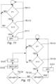
- Fig. 11 illustrates a simplified flowchart according to embodiments of the present disclosure.
- the control system 7 detects if a force have been provided at test TE111. If a force have been provided, the control system tests whether the force provided fulfil the requirements of the first force F1, see test TE112. If the requirements are not complied with, the first control output is not provided. On the other hand, the requirements are complied with Test TE 112, the first control output OP1 is provided, see step S111.
- Fig. 12 illustrates a flow chart according to further embodiments of the present disclosure.
- the first and second test TE 121, 122 may be substantially identical to the tests 111, 112 of fig. 11 .
- the control system 7 moreover registers the state of the gripping part 5a, i.e. if it is in the first GP1 or second GP2 gripping part position.
- the locking system 9a, 9b should/may already have been disengaged by the handle when the gripping part was moved from the first gripping part position GP1 to the second gripping part position GP2, and hence, the first control output OP1 is provided to the actuator so that the actuator opens the building aperture cover.
- the locking system 9a, 9b may be disengaged (Step 122 - DEG LSY) prior to providing the first control output OP1 (Step S123) to the actuator.
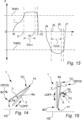
- Fig. 13 illustrates schematically various user interaction criteria/requirements that may be required to be fulfilled before control output OP1, OP2 is provided. For example according to the test 112, 121 described above.
- Force F is placed on Y-axis, and time t along x-axis.
- a pushing force F/touch is applied at the handle, e.g. in the direction of the glass unit, see e.g. user interaction F1 illustrated in fig 1A .
- the user interaction sensor arrangement 6 registers this user interaction, and at time t1, the applied force gets above a predetermined threshold THR1. This may in some embodiments of the present disclosure trigger that the first control output OP1 is provided.
- a further condition is required to be fulfilled before the first control output OP1 is provided.
- This condition comprises that a force larger than the threshold THR1 must have been applied for a certain amount of time, e.g. a predefined time period Tim1.
- the actuator continues to open the movable unit 3 to a predefined open position OPOS as the force F was in the force direction (See e.g. fig. 1A ) related to opening of the movable unit 3, and the threshold THR1 was exceeded for the time period Tim 1.
- the force F exceeds the threshold THR2, and at time t6, the timer Tim2 (starting at t5) has run out.
- the second control output OP2 is provided at time t6. This induces the actuator to stop if moving or if stopped then close the movable unit again, see e.g. fig. 2B , since the force F/user interaction applied can now be categorized as an activation force F1, F2.
- Tim2 for closing the movable unit 3 have been complied with.
- the time period Tim2 may be omitted and hence, the only requirement may be that the pulling force exceeds the threshold THR2.
- the thresholds THR1 THR2 values and/or timer Tim1, Tim2 periods may in some embodiments be identical for opening and closing the movable unit 3.
- the thresholds THR1 THR2 values and/or timer Tim1, Tim2 periods may in other embodiments be configured to be different dependent on if the movable unit 3 should be opened or closed, respectively.
- the threshold THR2 value may be lower than the THR1 value and/or the time period Tim2 may be lower/shorter than the time period Tim1.
- One, more than one, or all of THR1 THR2, Tim1 Tim2 may in embodiments of the present disclosure be predefined, for example predefined values stored in a data storage.
- the thresholds THR1 THR2 values may in some embodiments be binary such as a switch 0/1.
- the control system 7 comprises a user interaction detection system comprising one or more predefined user interaction criteria THR1, THR2, Tim1, Tim2 represented in a data storage.
- the control system is configured to process the sensor data SDA based on the user interaction criteria Such as the threshold THR1, THR2 and/or timer setting Tim1, Tim2, in order to determine if the control output OP1, OP2 should be provided.
- the control system 7 is configured to provide the control output OP1, OP2 if the user interaction criteria is determined to be complied with (at time t2 and t6). On the other hand, the control system 7 is configured to refrain from providing the control output OP1, OP2 if the user interaction criteria is determined to not be complied with.
- the threshold THR1, THR2 may be omitted, and a time setting Tim1, Tim2 may be provided, so that a user induced activation force (not needing to comply with a threshold) in a force direction needs to be provided in a predetermined time before the control output OP1, OP2 is provided.
- the time Tim 1, Tim2 may in embodiments be between 0.1 seconds and 1 seconds, such as between 0.1 seconds 0.7 seconds, such as between 0.1 second and 0.5 seconds.
- the opening and/or closing of the movable unit 3 may first be provided when one or more predefined user interaction patterns, such as tapping patterns have been detected.
- a controller 7 may, based on software program code, be configured to detect a predefined user interaction pattern, and first when this is complied with, the control output OP1 and/or OP2 is provided.
- the pattern may e.g. comprise a series of consecutive taps on the gripping unit, it may comprise a combination of long and short taps and/or the like.
- Fig. 14 illustrates schematically a building aperture 1 according to embodiments of the present disclosure, wherein the building aperture cover 1 is a top hung roof window according to embodiments of the present disclosure.
- a hinge arrangement 14 is arranged at the upper part, such as at the top TO, of the roof window 1, when the roof window is installed in a building roof structure (not illustrated).
- the handle 5 is arranged at the lower part, such as the bottom part of the movable frame 3, For example as illustrated in fig. 1A-2B .
- the longitudinal direction LDFF of the fixation frame 2 (extending between top and bottom of the window) is arranged with an angle that is neither perpendicular to, nor parallel with, horizontal HZ, but may e.g.
- the actuator 8a may open and close the movable unit 3 based on input from a user interaction sensor arrangement 6 as e.g. previously described, based on forces (not illustrated in fig. 14 , see e.g. figs 1A-2B ) provided at the handle. When inducing a force F1 by hand at the handle 5, the actuator 8a starts closing the movable unit
- Fig. 15 illustrates schematically a building aperture 1 according to embodiments of the present disclosure, wherein the building aperture cover 1 is a window configured to be installed vertically in e.g. an exterior wall of a building.
- the fixation frame 2 has a longitudinal direction LDFF extending between top and bottom of the window, and this direction is substantially perpendicular to horizontal HZ when the window is installed in an exterior wall of a building.
- a hinge arrangement 14 is arranged at the lower part, such as at the bottom part BO, of the window 1, when the window is installed in an exterior, vertical building wall (not illustrated).
- the handle 5 is arranged at a side part of the movable unit 3 between top TO and bottom BO of the movable unit 3, such as substantially midway between TO and BO.
- the actuator 8a may open and close the movable unit 3 based on input from a user interaction sensor arrangement 6 as e.g. previously described, based on forces F1, F2 provided at the handle.
- Fig. 16A-16B illustrates schematically an embodiment of the present disclosure, wherein the building aperture cover 1 is a door, such as a sliding door.
- the sliding door 1 comprises a movable unit 3 configured to move towards the open position OPOS from the closed position CPOS in a direction substantially parallel to a plane defined by a major outer surface 4a of the glass unit 4 of the movable unit 3.
- the movable unit 3 comprises a handle 5 with a gripping part 5a as described according to one or more embodiments above.
- the user interaction sensor arrangement 6 detects this and provides sensor data based thereon as e.g. previously described.
- a control system as e.g. previously described receives and process the sensor data SDA and provides control output OP1, OP2 based thereon (see e.g. figs. 1A-2B ).
- the actuator arrangement 8 receives this and opens or closes the movable unit 3 dependent on the direction of the force applied on the handle.
- the force provided at the gripping part 5a of the handle is a force F1 (See fig. 16A ) in the movement direction MD1 of the movable unit 3 when the movable unit is opened, and hence, the actuator arrangement 8 moves (see fig. 16b ) the movable unit from a closed position CPOS to the open position OPOS.
- the first F1 and/or second activation force F2 is/are configured to be in a direction parallel to a plane PL comprising the outer major surface 4a.
- first F1 and second F2 activation forces may be substantially oppositely directed.
- operation of the actuator arrangement 8 may be configured to be omitted despite the first and/or second activation force F1, F2 being provided onto the gripping part 5a. This may depend on circumstances and the design of the building aperture cover 1.
- operation of the actuator arrangement 8 may be configured to be omitted despite the first and/or second activation force F1, F2 being provided onto the gripping part 5a if the gripping part 5a is arranged in a second gripping part position GP2, such as when arranged manually in the second gripping part position GP2 by means of human hand, since this may provide/indicate that a human user intends to control such as open the movable unit manually.
- moving the gripping part to the second gripping part position GP2 may disengage the actuator 8a from the movable unit 3. Also here, it may not be desired to activate the actuator arrangement 8.
- operation of the actuator arrangement 8 may be configured to be omitted despite the first and/or second activation force F1, F2 being provided onto the gripping part 5a if the gripping part 5a is in the first gripping part position GP1.
- a locking system 9a, 9b see e.g. fig. 3
- the opening force OF1 should not be provided by the actuator arrangement 8.
- an activation force such as activation force F1 is applied.
- a state of the locking system may instead be detected.
- the locking system may automatically be disengaged before the opening force is provided, or the activation of the actuator arrangement 8 may provide that the locking system disengages.
- the omission of operating the actuator arrangement if the gripping part is arranged in the first or second gripping part position, despite that an activation force is provided to the gripping arrangement, may e.g. in e one or more embodiments of the present disclosure be obtained by means of
- a handle state sensor (not illustrated) may be provided, e.g. integrated in the handle 5.
- This handle state sensor is configured to detect/determine the handle position, for example by detecting directly or indirectly whether the gripping part is in the first or second gripping part position (relative to the movable unit). This may e.g. be provided by means of an accelerometer, a Hall sensor and/or the like. If the handle 5 /gripping part 5a is detected by the handle state sensor to be in the first gripping part position GP1, an omission of operating the actuator arrangement 8 may be provided.
- actuator operation may be accepted when an activation force F1/F2 is provided at the gripping part 5a.
- the first and/or second control output may be provided in response to an activation force.
- a unit position sensor such as an accelerometer, an angular sensor and/or the like, may in embodiments of the present disclosure be provided in order to determine the position of the movable unit 3. For example, an omission of operation of the actuator arrangement may occur if the gripping part 5a is detected to be in the first gripping part position GP1 and if the movable unit is detected to be in a closed position CPOS. If, on the other hand, the movable unit 3 is detected to be in an open position, the closing force and/or opening force provided by the actuator arrangement 8 may still be allowed to be provided, e.g. dependent or independent on the handle 5 position/state.
- a "filtering" may be provided so as to neglect force vectors in other directions than predefined force directions. For example force components other than force components extending normal to a major surface of the glass unit (or a plane PL1 as previously described), may be neglected.
- the relevant force components to be monitored may e.g. depend on window type, handle type and/or window installation angle.
- the user interaction sensor arrangement 6 may in embodiments comprise one user interaction sensor. In other embodiments, the user interaction sensor arrangement 6 may comprise two or more sensors configured to detect user interactions.
- Fig. 18 illustrates schematically an embodiment of the present disclosure, wherein the user interaction sensor arrangement 6 comprises two sensors 6a, 6b, for example capacitive sensors or the like.
- the sensors may be touch sensors.
- These sensors 6a, 6b are configured to detect user interactions F1, F2 provided at two opposite surfaces SP1, SP2 of the handle 5.
- These surfaces comprises a surface part SP1 of the gripping part 5a facing the plane PL1 (provided/defined by the glass sheet surface 4a), and a surface part SP2 of the gripping part 5a facing away from the plane PL1, respectively.
- the capacitive sensor or sensors 6a, 6b of the handle may not as such detect the force applied to the gripping part, but may rather detect/register the touching of the gripping part 5a itself. This will however also reflect an activation force F1, F2 provided to the handle by human hand.
- one of the sensors 6a of the user interaction sensor arrangement 6, may be configured to detect an opening first user interaction F1. This is when the user pushes the surface SP2. This is when the user pushes the surface SP1 facing away from the plane PL1.
- the other of the sensors 6b of the user interaction sensor arrangement 6 may is configured to detect a closing second activation force F2. This is when the user pushes the surface SP1 facing the plane PL.
- the output from the sensors, i.e. the sensor data, is provided to the control system 7, and an actuator arrangement 8 (not illustrated in fig. 1 ) is operated based thereon.
- user interactions F1, F2 configured to be detected for opening or closing the movable unit 3 may vary dependent on the type and/or design of building aperture cover 1 and/or handle type. This is also the case according to the various embodiments described above.
- a pulling force applied/induced at the gripping part 5a by human hand at the gripping part 5a may induce the actuator arrangement 8 to open the movable unit 3 (see e.g. F1 in fig. 7 ), whereas a pushing force applied/induced at the gripping part 5a by human hand may induce the actuator to close the movable unit 3.
- the opposite may be the case for other building aperture covering solutions such as e.g. as illustrated in figs. 1A-2B and other embodiments described above.
- Fig. 19 illustrates schematically an embodiment of the present disclosure, wherein building aperture covers 1 are installed in a building. 35.
- the building aperture covers 1 are installed to cover an aperture in an outer wall 320 or in a roof structure 310, respectively, of the building 300.
- Fig. 20 illustrates schematically an embodiment of the present disclosure, wherein a maximum time limit Maxt is applied.
- the control system is here configured to refrain from providing the control output OP1, OP2 if the physical user interaction F1, F2 applied to the gripping part 5a has been provided for more than the maximum time limit Maxt.
- the maximum time limit Maxt may be predefined. In some embodiments, the maximum time limit Maxt may be be more than 0.1 second and less than three seconds, such as more than 0.2 second and less than 1 second, such as less than 0.7 seconds.
- the human user pushes the gripping part. This starts/initiates a timer/counter counting from t0. As can be seen, the user releases the gripping part at time t1, before the timer expires at t2. This provides that the user interaction is acknowledged as an activation force, and hence, the control output OP1 or OP2 is provided.
- the human user pushes the gripping part 5a. This starts the timer/counter. As can be seen, the user does not release the gripping part before the timer expires at t4 (i.e. the maximum time limit Maxt is exceeded). This provides that the user interaction is not acknowledged as an activation force, and hence, the control output OP1 or OP2 is not provided.
- Fig. 21 illustrates schematically an embodiment of the present disclosure, where the control system 7 is configured to refrain from providing said control output OP1, OP2 because a first sensor detects a opening first user interaction at the gripping part 5a and the second opposite sensor simultaneously detects a closing second user interaction at the gripping part 5a.
- the control system tests if first user interaction F1 is present and the second user interaction F2 is absent. If this is the case (and other possible criteria are complied with, if relevant), the first control output OP1 is provided at step S211. If this is not the case, the control system tests in test TE212 if the second user interaction F2 is present and the first user interaction F1 is absent.
- the second control output OP2 is provided at step S212. This solution may provide that if both user interactions are detected, neither the first control output OP1 nor the second control output OP2 are provided.
- test TE213 may in further or alternative embodiments of the present disclosure be provided.
- this test TE213 it is tested whether both user interactions are present. This may for example be the case if two sensors for detecting oppositely directed user interactions F1, F2, are activated simultaneously, for example because the gripping part 5a is grasped by hand. See for example the embodiment of fig. 18 comprising sensors 6a, 6b. If this test TE213 is positive, it is assured (Step S S213) that neither of the control outputs OP1, OP2 are provided, since this situation may reflect that a user manually wants to control the movable unit 3. The test TE213 may in some embodiments be unnecessary if the tests TE211, TE212 are provided, as these only will be positive (YES) if one of the user interactions are provided.
- the test TE213 (and the associated step S213) may in some embodiments be provided instead of the tests TE211, TE212.
- test TE212 is negative and the test TE213 is omitted, the flow chart may return to the upper circle from the test TE212 instead of from test TE213 as is the case in fig. 21 .
- test TE213 and/or tests TE211 and/or TE212 may in some embodiments be implemented in one of the flow charts of fig. 11 and/or 12.
Landscapes
- Power-Operated Mechanisms For Wings (AREA)
- Lock And Its Accessories (AREA)
Priority Applications (2)
| Application Number | Priority Date | Filing Date | Title |
|---|---|---|---|
| EP23159064.7A EP4424965A1 (de) | 2023-02-28 | 2023-02-28 | Gebäudeöffnungsabdeckung mit einem griff mit einer benutzerinteraktionssensoranordnung |
| EP24151156.7A EP4424966A1 (de) | 2023-02-28 | 2024-01-10 | Gebäudeöffnungsabdeckung mit einem griff mit einer benutzerinteraktionssensoranordnung |
Applications Claiming Priority (1)
| Application Number | Priority Date | Filing Date | Title |
|---|---|---|---|
| EP23159064.7A EP4424965A1 (de) | 2023-02-28 | 2023-02-28 | Gebäudeöffnungsabdeckung mit einem griff mit einer benutzerinteraktionssensoranordnung |
Publications (1)
| Publication Number | Publication Date |
|---|---|
| EP4424965A1 true EP4424965A1 (de) | 2024-09-04 |
Family
ID=85410134
Family Applications (2)
| Application Number | Title | Priority Date | Filing Date |
|---|---|---|---|
| EP23159064.7A Withdrawn EP4424965A1 (de) | 2023-02-28 | 2023-02-28 | Gebäudeöffnungsabdeckung mit einem griff mit einer benutzerinteraktionssensoranordnung |
| EP24151156.7A Pending EP4424966A1 (de) | 2023-02-28 | 2024-01-10 | Gebäudeöffnungsabdeckung mit einem griff mit einer benutzerinteraktionssensoranordnung |
Family Applications After (1)
| Application Number | Title | Priority Date | Filing Date |
|---|---|---|---|
| EP24151156.7A Pending EP4424966A1 (de) | 2023-02-28 | 2024-01-10 | Gebäudeöffnungsabdeckung mit einem griff mit einer benutzerinteraktionssensoranordnung |
Country Status (1)
| Country | Link |
|---|---|
| EP (2) | EP4424965A1 (de) |
Citations (5)
| Publication number | Priority date | Publication date | Assignee | Title |
|---|---|---|---|---|
| DE19911592A1 (de) * | 1999-03-16 | 2000-09-28 | Webasto Vehicle Sys Int Gmbh | Manuell betätigtes Antriebssystem für ein motorisch verstellbares Schließteil eines Fahrzeugs |
| US20070170729A1 (en) | 2003-12-31 | 2007-07-26 | Shuco International Kg | Window and window handle |
| EP2281984A1 (de) | 2009-06-29 | 2011-02-09 | VKR Holding A/S | Verschlussanordnung |
| CN109339619A (zh) * | 2018-09-04 | 2019-02-15 | 张健 | 一种智能排烟门窗及其使用方法 |
| EP3848540A1 (de) | 2020-01-10 | 2021-07-14 | VKR Holding A/S | Schliessblech für eine schlossanordnung, besagte schlossanordnung und fenster mit besagter schlossanordnung |
Family Cites Families (1)
| Publication number | Priority date | Publication date | Assignee | Title |
|---|---|---|---|---|
| PT3556981T (pt) * | 2018-04-19 | 2020-05-11 | Hydro Extruded Solutions As | Dispositivo e método para a abertura manual e motorizada de uma janela oscilobatente |
-
2023
- 2023-02-28 EP EP23159064.7A patent/EP4424965A1/de not_active Withdrawn
-
2024
- 2024-01-10 EP EP24151156.7A patent/EP4424966A1/de active Pending
Patent Citations (5)
| Publication number | Priority date | Publication date | Assignee | Title |
|---|---|---|---|---|
| DE19911592A1 (de) * | 1999-03-16 | 2000-09-28 | Webasto Vehicle Sys Int Gmbh | Manuell betätigtes Antriebssystem für ein motorisch verstellbares Schließteil eines Fahrzeugs |
| US20070170729A1 (en) | 2003-12-31 | 2007-07-26 | Shuco International Kg | Window and window handle |
| EP2281984A1 (de) | 2009-06-29 | 2011-02-09 | VKR Holding A/S | Verschlussanordnung |
| CN109339619A (zh) * | 2018-09-04 | 2019-02-15 | 张健 | 一种智能排烟门窗及其使用方法 |
| EP3848540A1 (de) | 2020-01-10 | 2021-07-14 | VKR Holding A/S | Schliessblech für eine schlossanordnung, besagte schlossanordnung und fenster mit besagter schlossanordnung |
Also Published As
| Publication number | Publication date |
|---|---|
| EP4424966A1 (de) | 2024-09-04 |
Similar Documents
| Publication | Publication Date | Title |
|---|---|---|
| EP3239439B1 (de) | Zu öffnendes dachfenster mit aktivem schloss | |
| AU2017371116B2 (en) | Automatic door operator for a swing door assembly | |
| CA2942126C (en) | Powered actuator | |
| US20080021619A1 (en) | Device For Actuating An Electric Or Mechanical Closing Device On A Door And/Or Lid Of A Vehicle | |
| US20190277071A1 (en) | Flap for handless closure panel in motor vehicles | |
| US20200284068A1 (en) | Latch with integrated door presenter and remote actuator | |
| US20120175896A1 (en) | Vehicle door latch | |
| KR101744888B1 (ko) | 창문의 잠금장치 | |
| GB2379480A (en) | Safety device for releasing a locked door of a chamber from within the chamber | |
| US12227982B2 (en) | Testing system for swing door-based entrance system | |
| EP4424966A1 (de) | Gebäudeöffnungsabdeckung mit einem griff mit einer benutzerinteraktionssensoranordnung | |
| CA2707271A1 (en) | Window with electrical connection to operable sash | |
| WO1997001010A1 (en) | Opening arrangements and methods for closure members | |
| KR200442949Y1 (ko) | 패닉 릴리스 감지 기능을 구비한 디지털 도어락 | |
| JPH01192979A (ja) | ドア自動開閉装置 | |
| EP2157262B1 (de) | Dachfenster mit Einbruchschutz | |
| EP3604720B1 (de) | Motorisiertes verschlusssystem und verfahren | |
| KR20160146416A (ko) | 창문의 잠금장치 | |
| JP2000008679A (ja) | クレセント | |
| JPH09296671A (ja) | 建物用の開閉装置 | |
| CN208564276U (zh) | 一种防夹安全门 | |
| EP1707720B1 (de) | Kippfenstereinheit | |
| JP5336922B2 (ja) | 建物のシャッタ制御装置 | |
| KR102964016B1 (ko) | 비상 탈출 기능이 구비된 방범 창살 | |
| NL2032287B1 (en) | Door closing device, doorway system, and door closing method |
Legal Events
| Date | Code | Title | Description |
|---|---|---|---|
| PUAI | Public reference made under article 153(3) epc to a published international application that has entered the european phase |
Free format text: ORIGINAL CODE: 0009012 |
|
| STAA | Information on the status of an ep patent application or granted ep patent |
Free format text: STATUS: THE APPLICATION HAS BEEN PUBLISHED |
|
| AK | Designated contracting states |
Kind code of ref document: A1 Designated state(s): AL AT BE BG CH CY CZ DE DK EE ES FI FR GB GR HR HU IE IS IT LI LT LU LV MC ME MK MT NL NO PL PT RO RS SE SI SK SM TR |
|
| STAA | Information on the status of an ep patent application or granted ep patent |
Free format text: STATUS: THE APPLICATION IS DEEMED TO BE WITHDRAWN |
|
| 18D | Application deemed to be withdrawn |
Effective date: 20250305 |