EP4425014A1 - Getriebegehäuse und elektrische hilfsvorrichtung - Google Patents
Getriebegehäuse und elektrische hilfsvorrichtung Download PDFInfo
- Publication number
- EP4425014A1 EP4425014A1 EP22886635.6A EP22886635A EP4425014A1 EP 4425014 A1 EP4425014 A1 EP 4425014A1 EP 22886635 A EP22886635 A EP 22886635A EP 4425014 A1 EP4425014 A1 EP 4425014A1
- Authority
- EP
- European Patent Office
- Prior art keywords
- worm
- wheel
- housing section
- axial direction
- rib
- Prior art date
- Legal status (The legal status is an assumption and is not a legal conclusion. Google has not performed a legal analysis and makes no representation as to the accuracy of the status listed.)
- Pending
Links
Images







Classifications
-
- B—PERFORMING OPERATIONS; TRANSPORTING
- B62—LAND VEHICLES FOR TRAVELLING OTHERWISE THAN ON RAILS
- B62D—MOTOR VEHICLES; TRAILERS
- B62D5/00—Power-assisted or power-driven steering
- B62D5/04—Power-assisted or power-driven steering electrical, e.g. using an electric servo-motor connected to, or forming part of, the steering gear
- B62D5/0403—Power-assisted or power-driven steering electrical, e.g. using an electric servo-motor connected to, or forming part of, the steering gear characterised by constructional features, e.g. common housing for motor and gear box
-
- F—MECHANICAL ENGINEERING; LIGHTING; HEATING; WEAPONS; BLASTING
- F16—ENGINEERING ELEMENTS AND UNITS; GENERAL MEASURES FOR PRODUCING AND MAINTAINING EFFECTIVE FUNCTIONING OF MACHINES OR INSTALLATIONS; THERMAL INSULATION IN GENERAL
- F16H—GEARING
- F16H57/00—General details of gearing
- F16H57/02—Gearboxes; Mounting gearing therein
- F16H57/039—Gearboxes for accommodating worm gears
-
- B—PERFORMING OPERATIONS; TRANSPORTING
- B62—LAND VEHICLES FOR TRAVELLING OTHERWISE THAN ON RAILS
- B62D—MOTOR VEHICLES; TRAILERS
- B62D5/00—Power-assisted or power-driven steering
- B62D5/04—Power-assisted or power-driven steering electrical, e.g. using an electric servo-motor connected to, or forming part of, the steering gear
- B62D5/0409—Electric motor acting on the steering column
-
- B—PERFORMING OPERATIONS; TRANSPORTING
- B62—LAND VEHICLES FOR TRAVELLING OTHERWISE THAN ON RAILS
- B62D—MOTOR VEHICLES; TRAILERS
- B62D5/00—Power-assisted or power-driven steering
- B62D5/04—Power-assisted or power-driven steering electrical, e.g. using an electric servo-motor connected to, or forming part of, the steering gear
- B62D5/0442—Conversion of rotational into longitudinal movement
- B62D5/0454—Worm gears
-
- F—MECHANICAL ENGINEERING; LIGHTING; HEATING; WEAPONS; BLASTING
- F16—ENGINEERING ELEMENTS AND UNITS; GENERAL MEASURES FOR PRODUCING AND MAINTAINING EFFECTIVE FUNCTIONING OF MACHINES OR INSTALLATIONS; THERMAL INSULATION IN GENERAL
- F16H—GEARING
- F16H1/00—Toothed gearings for conveying rotary motion
- F16H1/02—Toothed gearings for conveying rotary motion without gears having orbital motion
- F16H1/04—Toothed gearings for conveying rotary motion without gears having orbital motion involving only two intermeshing members
- F16H1/12—Toothed gearings for conveying rotary motion without gears having orbital motion involving only two intermeshing members with non-parallel axes
- F16H1/16—Toothed gearings for conveying rotary motion without gears having orbital motion involving only two intermeshing members with non-parallel axes comprising worm and worm-wheel
-
- F—MECHANICAL ENGINEERING; LIGHTING; HEATING; WEAPONS; BLASTING
- F16—ENGINEERING ELEMENTS AND UNITS; GENERAL MEASURES FOR PRODUCING AND MAINTAINING EFFECTIVE FUNCTIONING OF MACHINES OR INSTALLATIONS; THERMAL INSULATION IN GENERAL
- F16H—GEARING
- F16H57/00—General details of gearing
- F16H57/02—Gearboxes; Mounting gearing therein
- F16H57/021—Shaft support structures, e.g. partition walls, bearing eyes, casing walls or covers with bearings
-
- F—MECHANICAL ENGINEERING; LIGHTING; HEATING; WEAPONS; BLASTING
- F16—ENGINEERING ELEMENTS AND UNITS; GENERAL MEASURES FOR PRODUCING AND MAINTAINING EFFECTIVE FUNCTIONING OF MACHINES OR INSTALLATIONS; THERMAL INSULATION IN GENERAL
- F16H—GEARING
- F16H57/00—General details of gearing
- F16H57/02—Gearboxes; Mounting gearing therein
- F16H57/03—Gearboxes; Mounting gearing therein characterised by means for reinforcing gearboxes, e.g. ribs
-
- F—MECHANICAL ENGINEERING; LIGHTING; HEATING; WEAPONS; BLASTING
- F16—ENGINEERING ELEMENTS AND UNITS; GENERAL MEASURES FOR PRODUCING AND MAINTAINING EFFECTIVE FUNCTIONING OF MACHINES OR INSTALLATIONS; THERMAL INSULATION IN GENERAL
- F16H—GEARING
- F16H57/00—General details of gearing
- F16H57/02—Gearboxes; Mounting gearing therein
- F16H57/031—Gearboxes; Mounting gearing therein characterised by covers or lids for gearboxes
-
- F—MECHANICAL ENGINEERING; LIGHTING; HEATING; WEAPONS; BLASTING
- F16—ENGINEERING ELEMENTS AND UNITS; GENERAL MEASURES FOR PRODUCING AND MAINTAINING EFFECTIVE FUNCTIONING OF MACHINES OR INSTALLATIONS; THERMAL INSULATION IN GENERAL
- F16H—GEARING
- F16H57/00—General details of gearing
- F16H57/02—Gearboxes; Mounting gearing therein
- F16H57/032—Gearboxes; Mounting gearing therein characterised by the materials used
-
- B—PERFORMING OPERATIONS; TRANSPORTING
- B62—LAND VEHICLES FOR TRAVELLING OTHERWISE THAN ON RAILS
- B62D—MOTOR VEHICLES; TRAILERS
- B62D1/00—Steering controls, i.e. means for initiating a change of direction of the vehicle
- B62D1/02—Steering controls, i.e. means for initiating a change of direction of the vehicle vehicle-mounted
- B62D1/16—Steering columns
- B62D1/18—Steering columns yieldable or adjustable, e.g. tiltable
- B62D1/187—Steering columns yieldable or adjustable, e.g. tiltable with tilt adjustment; with tilt and axial adjustment
- B62D1/189—Steering columns yieldable or adjustable, e.g. tiltable with tilt adjustment; with tilt and axial adjustment the entire column being tiltable as a unit
-
- F—MECHANICAL ENGINEERING; LIGHTING; HEATING; WEAPONS; BLASTING
- F16—ENGINEERING ELEMENTS AND UNITS; GENERAL MEASURES FOR PRODUCING AND MAINTAINING EFFECTIVE FUNCTIONING OF MACHINES OR INSTALLATIONS; THERMAL INSULATION IN GENERAL
- F16H—GEARING
- F16H57/00—General details of gearing
- F16H57/02—Gearboxes; Mounting gearing therein
- F16H2057/02039—Gearboxes for particular applications
-
- F—MECHANICAL ENGINEERING; LIGHTING; HEATING; WEAPONS; BLASTING
- F16—ENGINEERING ELEMENTS AND UNITS; GENERAL MEASURES FOR PRODUCING AND MAINTAINING EFFECTIVE FUNCTIONING OF MACHINES OR INSTALLATIONS; THERMAL INSULATION IN GENERAL
- F16H—GEARING
- F16H57/00—General details of gearing
- F16H57/02—Gearboxes; Mounting gearing therein
- F16H57/032—Gearboxes; Mounting gearing therein characterised by the materials used
- F16H2057/0325—Moulded casings made from plastic
Definitions
- the present disclosure relates to an electric assist device and a gear housing of the electric assist device.
- Electric power steering devices equipped with an electric assist device for applying auxiliary power to a steering force transmission path is widely used as a device for reducing the force required for operation of steering wheel when applying a steering angle to the steered wheel of an automobile.
- Electric power steering devices are roughly classified in structure depending on the mounting position of the electric assist device. Specifically, various structures have been proposed, such as a column assist type that applies auxiliary power to the steering shaft rotatably supported inside the steering column, a pinion assist type that applies auxiliary power to the pinion shaft that is an input shaft of the steering gear unit, and a dual pinion type in which the steering gear unit is provided with another pinion shaft separate from the pinion shaft that is the input shaft and applies auxiliary power to the separate pinion shaft.
- a column assist type that applies auxiliary power to the steering shaft rotatably supported inside the steering column
- a pinion assist type that applies auxiliary power to the pinion shaft that is an input shaft of the steering gear unit
- a dual pinion type in which the steering gear unit is provided with another pinion shaft separate from the pinion shaft that is the input shaft and applies auxiliary power to the separate pinion shaft.
- the electric assist device includes an electric motor serving as a power source and a reduction gear, and applies auxiliary power from the electric motor to a shaft member that rotates or moves linearly due to the operation of the steering wheel through the reduction gear.
- reduction gear a worm reduction gear is widely used.
- the worm reduction gear includes a worm wheel and a worm that is rotationally driven by an electric motor.
- the worm wheel has wheel teeth on the outer circumferential surface.
- the worm has worm teeth that mesh with the wheel teeth on the outer circumferential surface.
- the worm wheel and the worm are accommodated inside the gear housing.
- the gear housing includes a wheel housing section that accommodates a worm wheel inside, and a worm housing section that accommodates a worm inside.
- the worm housing section is arranged at a skewed position with respect to the wheel housing section, and is connected to a portion in the circumferential direction at an end portion on the outer side in the radial direction of the wheel housing section.
- the worm wheel is rotatably supported inside the wheel housing section by a bearing for wheel.
- the worm is rotatably supported inside the worm housing section by a bearing for worm.
- the electric motor is supported at an end portion on one side in the axial direction of the worm housing section, and rotationally drives the worm during use.
- the electric assist device increases torque by transmitting auxiliary power generated by the electric motor to the worm wheel through the worm and applies it to a shaft member that rotates or moves linearly due to the operation of the steering wheel so as to reduce power required for the operator to operate the steering wheel.
- a meshing reaction force is applied from a meshing portion between the worm teeth and the wheel teeth to the worm and the worm wheel. Further, the meshing reaction force is transmitted to the worm housing section through a bearing for worm for rotatably supporting the worm inside the worm housing section, and is transmitted to the wheel housing section through a bearing for wheel for rotatably supporting the worm wheel inside the wheel housing section.
- a force in a direction separating the worm housing section and the wheel housing section from each other and a force in a direction that they are twisted relative to each other are applied to the gear housing.
- WO 2019/087945 (A1 ) discloses a structure in which a gear housing is provided with a rib, and a worm housing section and a wheel housing section are connected by the rib.
- Patent Literature 1 WO 2019/087945 (A1 )
- the rib provided in the gear housing connects the worm housing section and the wheel housing section, therefore, it is possible to suppress deformation of the gear housing due to the force in a direction separating the worm housing section and the wheel housing section from each other and the force in a direction that they are twisted relative to each other, acting on the gear housing when auxiliary torque is generated.
- the positions of the ribs are determined in consideration of improving the fluidity of the material when manufacturing the gear housing by casting or injection molding. As a result, there is room for improvement in terms of more effectively suppressing deformation of the gear housing by the ribs provided in the gear housing.
- the object of the present disclosure is to provide a gear housing capable of effectively suppressing deformation during use, and an electric assist device including the gear housing.
- the gear housing includes a wheel housing section that accommodates a worm wheel inside, and a worm housing section that accommodates a worm inside.
- the wheel housing section has a tubular portion for wheel arranged around the worm wheel, a circular bottom portion for wheel extending from an end portion of the tubular portion for wheel on one side in an axial direction of the wheel housing section toward an inner side in a radial direction, and a fitting tubular portion for wheel that is connected to an end portion on the inner side in the radial direction of the bottom portion for wheel and into which a bearing for wheel for supporting the worm wheel is internally fitted.
- the worm housing section has a tubular shape with at least an end portion on one side in an axial direction of the worm housing section is open, has a center axis that is arranged at a skewed position with respect to a center axis of the wheel housing section, and is connected to a portion in a circumferential direction of an end portion on an outer side in the radial direction of the wheel housing section.
- the worm housing section has fitting tubular portions for worm at two locations separated in the axial direction of the worm housing section into which a bearing for worm for supporting the worm or a bearing holder holding the bearing for worm is internally fitted.
- the gear housing according to one aspect of the present disclosure includes a one side rib that protrudes from a side surface of the bottom portion for wheel on the one side in the axial direction of the wheel housing section and connects the fitting tubular portion for wheel and a fitting tubular portion for worm on the one side in the axial direction of the worm housing section of the fitting tubular portions for worm at two locations.
- the one side rib extends in a radial direction centered on a center axis of the bottom portion for wheel.
- the one side rib is arranged on a straight line that connects the center axis of the bottom portion for wheel and a center point of the fitting tubular portion for worm on the one side in the axial direction of the worm housing section when viewed from the one side in the axial direction of the wheel housing section.
- the gear housing according to one aspect of the present disclosure includes an other side rib that protrudes from a side surface of the bottom portion for wheel on the one side in the axial direction of the wheel housing section and connects the fitting tubular portion for wheel and a fitting tubular portion for worm on the other side in the axial direction of the worm housing section of the fitting tubular portion for worm at two locations.
- the other side rib extends in the radial direction centered on the center axis of the bottom portion for wheel.
- the other side rib is arranged on a straight line that connects the center axis of the bottom portion for wheel and a center point of the fitting tubular portion for worm on the other side in the axial direction of the worm housing section when viewed from the one side in the axial direction of the bottom portion for wheel.
- an end portion on the other side in the axial direction of the worm housing section is also open, and a width dimension in the circumferential direction of the other side rib is larger than a width dimension in the circumferential direction of the one side rib.
- an end portion on the other side in the axial direction of the worm housing section is also open, an end portion on an outer side in the radial direction of the other side rib is located farther from the fitting tubular portion for wheel in a direction orthogonal to the axial direction of the worm housing section than an end portion on an outer side in the radial direction of the one side rib.
- the electric assist device of one aspect of the present disclosure includes a worm wheel having wheel teeth on an outer circumferential surface, a worm having worm teeth on an outer circumferential surface that mesh with the wheel teeth, a gear housing accommodating the worm wheel and the worm inside, and an electric motor supported by the gear housing and rotationally driving the worm, and the gear housing is configured by the gear housing according to one aspect of the present disclosure.
- the structure of the present disclosure may be implemented by optionally combining the respective aspects described above to the extent that no contradiction occurs.
- gear housing that can effectively suppress deformation during use, and an electric assist device provided with the gear housing.
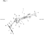
- FIG. 1 to FIG. 6 illustrate a first example of an embodiment of the present disclosure.
- an electric assist device of one aspect of the present disclosure is applied to a column assist type electric power steering device.
- the electric assist device of the present disclosure can also be applied to a pinion assist type or dual pinion type electric power steering device.
- the electric power steering device 1 of this example includes a steering wheel 2, a steering shaft 3, a steering column 4, a pair of universal joints 5a, 5b, an intermediate shaft 6, a steering gear unit 7, and an electric assist device 8.
- the forward-backward direction is the forward-backward direction of a vehicle
- the left-right direction is the width direction of the vehicle.
- the steering wheel 2 is supported and fixed to the rear end portion of the steering shaft 3.
- the steering shaft 3 is rotatably supported inside the steering column 4 that is supported by a vehicle body.
- the front end portion of the steering shaft 3 is connected to a pinion shaft 9 of the steering gear unit 7 through a rear-side universal joints 5a, an intermediate shaft 6, and a front-side universal joint 5b. Therefore, when the driver rotates the steering wheel 2, the rotation of the steering wheel 2 is transmitted to the pinion shaft 9 through the steering shaft 3, the pair of universal joints 5a, 5b, and the intermediate shaft 6.
- the rotation of the pinion shaft 9 is converted into linear motion of a rack shaft (not illustrated) of the steering gear unit 7 engaged with the pinion shaft 9.
- the pair of tie rods 10 are pushed and pulled, and a steering angle is applied to the left and right steered wheels according to the amount of operation of the steering wheel 2.
- the electric power steering device 1 of this example includes a tilt mechanism for adjusting the up-down position of the steering wheel 2 in accordance with the size and operating posture of the operator. Due to this, the electric assist device 8 fixed to the front end portion of the steering column 4 is supported with respect to the vehicle body so as to pivotally displace around a tilt shaft 11 in the left-right direction. The up-down position of the steering wheel 2 is adjusted by swinging the steering shaft 3, the steering column 4, and the electric assist device 8 in the vertical direction about the tilt shaft 11.
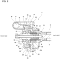
- the electric assist device 8 includes a worm wheel 12 having wheel teeth 13 on the outer circumferential surface, a worm 14 having worm teeth 15 on the outer circumferential surface that engage with the wheel teeth 13, a gear housing 16 that accommodates the worm wheel 12 and the worm 14 inside, and an electric motor 17 that is supported by the gear housing 16 and rotationally drives the worm 14.
- the electric power steering device 1 of this example further includes a sensor housing 18 fixed to the front end portion of the steering column 4.
- the housing 19 is formed by connecting the gear housing 16 arranged on the front side and the sensor housing 18 arranged on the rear side in the forward-backward direction with a plurality of bolts 20.
- the electric power steering device 1 of this example further includes a torsion bar 21 and an output shaft 22.
- the front end portion of the steering shaft 3 is inserted on the inside of the housing 19 and connected to the output shaft 22 through the torsion bar 21.
- the front end portion of the output shaft 22 protrudes toward the front side from the inside of the housing 19 and is connected to the intermediate shaft 6 through the rear-side universal joint 5a (see FIG. 1 ).
- the output shaft 22 is rotatably supported by ball bearings 23, 24 with respect to the housing 19 at two locations separated in the axial direction.
- the electric power steering device 1 of this example further includes a torque sensor 25 accommodated inside the sensor housing 18 and arranged around the output shaft 22.
- the torque sensor 25 detects the direction and magnitude of torque applied from the steering wheel 2 to the steering shaft 3.
- the electric motor 17 rotationally drives the worm 14 based on, for example, the detected signal from the torque sensor 25 and the vehicle speed signal output from the vehicle speed sensor assembled in the transmission so as to apply auxiliary power to the output shaft 22 through the worm wheel 12. As a result, the force required for the driver to rotate the steering wheel 2 is reduced.
- the gear housing 16, worm 14, worm wheel 12, and electric motor 17 of the electric assist device 8 of this example will be further explained below.
- the gear housing 16 includes a wheel housing section 26 that accommodates the worm wheel 12 inside and a worm housing section 27 that accommodates the worm 14 inside.
- the gear housing 16 is made of a thermoplastic resin or a light alloy such as an aluminum alloy so as to be integrally configured as a whole. That is, the connections between parts of the gear housing 16 of this example, which will be explained below, mean integral connections, in other words, physically continuous connections.
- the gear housing 16 can be formed, for example, by inj ection molding of thermoplastic resin or die casting of a light alloy such as an aluminum alloy.
- the wheel housing section 26 has a cylindrical tubular portion for wheel 28 arranged around the worm wheel 12, a circular bottom portion for wheel 29 extending from an end portion of the tubular portion for wheel 28 on the front side corresponding to one side in the axial direction of the wheel housing section 26 toward the inner side in the radial direction, and a substantially cylindrical fitting tubular portion for wheel 30 connected to an end portion on the inner side in the radial direction of the bottom portion for wheel 29.
- the axial direction means the axial direction of the wheel housing section 26 and each of the components.
- the end portion on the inner side in the radial direction of the bottom portion for wheel 29 is connected to an intermediate portion in the axial direction of the fitting tubular portion for wheel 30.
- an annular rib 31 is formed by a portion of the fitting tubular portion for wheel 30 that protrudes further toward the front side than the side surface on the front side of the bottom portion for wheel 29.
- the worm housing section 27 is formed into a bottomed tubular shape where an end portion on the one side in the axial direction (right side in FIG. 3 and FIG. 4 ) of the worm housing section 27 to which the electric motor 17 is attached is open and the end portion on the other side in the axial direction (left side in FIG. 3 and FIG. 4 ) is closed.
- the axial direction means the axial direction of the worm housing section 27 and each of the components.
- the worm housing section may be formed into a tubular shape where the end portion on the one side in the axial direction and the end portion on the other side in the axial direction are both open, and the opening at the end portion on the other side in the axial direction may be closed with a lid.
- the worm housing section 27 is connected to a portion in the circumferential direction of an end portion on the outer side in the radial direction of the wheel housing section 26.
- the center axis of the worm housing section 27 is arranged at a skewed position with respect to the center axis of the wheel housing section 26.
- the internal space of the worm housing section 27 communicates with the internal space of the wheel housing section 26.
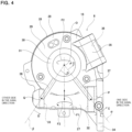
- the worm housing section 27 has substantially cylindrical fitting tubular portions for worm 32, 33 at two locations separated in the axial direction, specifically, at end portions on both sides in the axial direction, more specifically, in portions marked with diagonal grids in FIG. 3 and in portions surrounded by chain lines in FIG. 4 .
- Each of the fitting tubular portions for worm 32, 33 is a portion into which a bearing for worm for supporting the worm 14 with respect to the worm housing section 27 or a bearing holder holding the bearing for worm is internally fitted.
- the fitting tubular portion for worm 32 on the one side in the axial direction has a larger inner-diameter dimension and a width dimension in the axial direction than the fitting tubular portion for worm 33 on the other side in the axial direction.
- the worm housing section 27 optionally and additionally has a motor mounting flange 34 extending toward the outer side in the radial direction at the end portion on the one side in the axial direction.
- the motor mounting flange 34 is a portion to which the electric motor 17 is attached, and has a function of increasing the rigidity of the peripheral portion of the electric motor 17.
- the gear housing 16 optionally and additionally further includes a hinge portion 35.
- the hinge portion 35 protrudes toward the front side from a portion of an end portion on the outer side in the radial direction of the wheel housing section 26 that is separated from the worm housing section 27 in the circumferential direction.
- the hinge portion 35 has an insertion hole 36 for inserting the tilt shaft 11 (see FIG. 1 ).
- the hinge portion 35 is arranged at a position closer to the one side in the axial direction of the wheel housing section 26.
- the position of the hinge portion 35 in the circumferential direction of the wheel housing section 26 may be different from that of this example as long as it is separated from the worm housing section 27.
- the gear housing 16 optionally and additionally further includes coupling flanges 58 that protrude toward the outer side in the radial direction from two locations on opposite sides in the radial direction of the tubular portion for wheel 28.
- Each of the coupling flanges 58 has a bolt hole 59 for screwing or inserting the bolts 20 (see FIG. 2 ) for coupling the gear housing 16 and the sensor housing 18.
- one coupling flange 58 of the two coupling flanges 58 (one on the upper side in FIG. 2 ) is arranged at the same position in the circumferential direction as the hinge portion 35.
- the number and the phase of the arrangement in the circumferential direction of the coupling flange may be different from those of this example.
- the gear housing 16 further includes a one side rib 37.
- the one side rib 37 protrudes from the side surface on the front side which is the one side in the axial direction of the bottom portion for wheel 29 and from the side surface on the front side of the worm housing section 27, and connects the fitting tubular portion for wheel 30 and the fitting tubular portion for worm 32 on the one side in the axial direction of the two fitting tubular portions for worm 32, 33.
- the amount of protrusion toward the front side of the one side rib 37 can be set to an arbitrary magnitude.
- the front-side end portion of the one side rib 37 is positioned slightly rearward than the front-side end portion of the annular rib 31 by adjusting the amount of protrusion.
- the one side rib 37 extends in the radial direction centered on the center axis O of the bottom portion for wheel 29.
- the center axis O of the bottom portion for wheel 29 is also the center axis of the wheel housing section 26.
- the end portion on the inner side in the radial direction of the one side rib 37 is connected to the outer circumferential surface of the annular rib 31.
- the end portion on the outer side in the radial direction of the one side rib 37 is connected to the side surface on the front side of the fitting tubular portion for worm 32 on the one side in the axial direction.
- the end portion on the outer side in the radial direction of the one side rib 37 is firmly connected to the outer circumferential surface of the fitting tubular portion for worm 32 on the one side in the axial direction so as to overlap in the axial direction of the bottom portion for wheel 29.
- the extension direction of the one side rib that connects the fitting tubular portion for wheel and the fitting tubular portion for worm on the one side in the axial direction may be different from the radial direction centered on the center axis of the bottom portion for wheel.
- the end portion on the outer side in the radial direction of the one side rib 37 may be located on the outer side in the radial direction or the inner side in the radial direction than in the case of this example as long as it is connected to the fitting tubular portion for worm 32 on the one side in the axial direction.
- the one side rib 37 is arranged on a straight line ⁇ connecting the center axis O of the bottom portion for wheel 29 and the center point P of the fitting tubular portion for worm 32 on the one side in the axial direction when viewed from the front side of the bottom portion for wheel 29.
- the one side rib 37 extends in the direction of straight line ⁇ .
- the extension direction of the one side rib when the extension direction of the one side rib is the radial direction centered on the center axis of the bottom portion for wheel, the extension direction may also be a direction shifted by an arbitrary angle with respect to the direction of the straight line ⁇ .
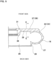
- the cross-sectional shape of the one side rib 37 specifically, the cross-sectional shape cut along an imaginary flat plane orthogonal to the extension direction is a solid rectangular shape, as illustrated in FIG. 6 .
- the cross-sectional shape may be an arbitrary shape.
- the gear housing 16 further includes the other side rib 38.
- the other side rib 38 protrudes from the side surface on the front side of the bottom portion for wheel 29 and from the side surface on the front side of the worm housing section 27, and connects the fitting tubular portion for wheel 30 and the fitting tubular portion for worm 33 on the other side in the axial direction of the two fitting tubular portions for worm 32, 33.
- the amount of protrusion toward the front side of the other side rib 38 can be set to an arbitrary magnitude.
- the front-side end portion of the other side rib 38 is positioned slightly rearward than the front-side end portion of the annular rib 31 by adjusting the amount of protrusion.
- the other side rib 38 extends in the radial direction centered on the center axis O of the bottom portion for wheel 29.
- the end portion on the inner side in the radial direction of the other side rib 38 is connected to the outer circumferential surface of the annular rib 31.
- the end portion on the outer side in the radial direction of the other side rib 38 is connected to the side surface on the front side of the fitting tubular portion for worm 33 on the other side in the axial direction.
- the end portion on the outer side in the radial direction of the other side rib 38 is firmly connected to the outer circumferential surface of the fitting tubular portion for worm 33 on the other side in the axial direction so as to overlap in the axial direction of the bottom portion for wheel 29.
- the extension direction of the other side rib that connects the fitting tubular portion for wheel and the fitting tubular portion for worm on the other side in the axial direction may be different from the radial direction centered on the center axis of the bottom portion for wheel.
- the end portion on the outer side in the radial direction of the other side rib 38 may be located on the outer side in the radial direction or on the inner side in the radial direction than in the case of this example as long as it is connected to the fitting tubular portion for worm 33 on the other side in the axial direction.
- the other side rib 38 is arranged on a straight line ⁇ connecting the center axis O of the bottom portion for wheel 29 and the center point Q of the fitting tubular portion for worm 33 on the other side in the axial direction when viewed from the front side of the bottom portion for wheel 29.
- the other side rib 38 extends in the direction of the straight line ⁇ .
- the extension direction of the other side rib when the extension direction of the other side rib is the radial direction centered on the center axis of the bottom portion for wheel, the extension direction may also be a direction shifted by an arbitrary angle with respect to the direction of the straight line ⁇ .
- the cross-sectional shape of the other side rib 38 is a solid rectangular shape, as illustrated in FIG. 6 .
- the cross-sectional shape may be an arbitrary shape.
- the height in the axial direction and the width in the circumferential direction of the one side rib 37 and the other side rib 38 are made approximately equal to each other, but in a case of implementing a configuration of the present disclosure, the height in the axial direction and the width in the circumferential direction of the one side rib may be larger than those of the other side rib.
- the worm 14 has worm teeth 15 that mesh with the wheel teeth 13 on the outer circumferential surface of the intermediate portion in the axial direction, and has a female spline 39 on the inner circumferential surface of the end portion on the one side in the axial direction.
- the worm 14 is rotatably supported inside the worm housing section 27 by ball bearings 40, 41, each of which is a bearing for worm.
- the ball bearing 40 includes an outer ring 42, an inner ring 43, and a plurality of balls 44.
- the outer ring 42 is internally fitted into the fitting tubular portion for worm 32 on the one side in the axial direction of the worm housing section 27.
- the inner ring 43 is externally fitted onto the end portion on the one side in the axial direction of the worm 14.
- the outer ring 42 may also be internally fitted into an annular bearing holder so as to hold the ball bearing 40 by the bearing holder, and the bearing holder may be internally fitted into the fitting tubular portion for worm 32 on the one side in the axial direction.
- the ball bearing 41 includes an outer ring 45, an inner ring 46, and a plurality of balls 47.
- the ball bearing 41 is held in the bearing holder 48 by internally fitting the outer ring 45 into the annular bearing holder 48.
- the bearing holder 48 is internally fitted into the fitting tubular portion for worm 33 on the other side in the axial direction of the worm housing section 27.
- the inner ring 46 is externally fitted onto the end portion on the other side in the axial direction of the worm 14.
- the outer ring 45 may also be directly internally fitted into the fitting tubular portion for worm 33 on the other side in the axial direction.
- the worm wheel 12 has wheel teeth 13 on the outer circumferential surface and is rotatably supported inside the wheel housing section 26. Due to this, in this example, the worm wheel 12 is externally fitted and fixed to a portion of the output shaft 22 located between two ball bearings 23, 24.
- the ball bearing 23, which is a bearing for wheel, includes an outer ring 49, an inner ring 50, and a plurality of balls 51.
- the outer ring 49 is internally fitted into the fitting tubular portion for wheel 30 of the wheel housing section 26.
- the inner ring 50 is externally fitted onto a portion of the output shaft 22 adjacent to the front side of the worm wheel 12.
- the ball bearing 24 includes an outer ring 52, an inner ring 53, and a plurality of balls 54.
- the outer ring 52 is internally fitted into the end portion on the front side of the sensor housing 18.
- the inner ring 53 is externally fitted onto a portion of the output shaft 22 adjacent to the rear side of the worm wheel 12.
- the center axis of the worm 14 and the center axis of the worm wheel 12 are orthogonal to each other when viewed from a direction orthogonal to both the center axis of the worm 14 and the center axis of the worm wheel 12.
- the gear housing 16 when viewed from a direction orthogonal to both the center axis of the worm housing section 27 and the center axis of the wheel housing section 26, the center axis of the worm housing section 27 and the center axis of the wheel housing section 26 are orthogonal to each other.
- the electric motor 17 is coupled and fixed to the motor mounting flange 34 of the worm housing section 27 with bolts (not illustrated).
- the electric motor 17 has a male spline 56 on the outer circumferential surface of the tip end portion of the output shaft 55.
- the output shaft 55 and the worm 14 are connected so as to transmit torque.
- the method of connecting the output shaft and the worm so as to transmit torque is not particularly limited. Fr example, it is also possible to connect the output shaft and the worm so as to transmit torque through a coupling that can absorb (allow) mutual misalignment.
- a meshing reaction force is applied to the worm 14 and the worm wheel 12 from the meshing portion between the worm teeth 15 and the wheel teeth 13. Further, this meshing reaction force is transmitted to the worm housing section 27 through the ball bearings 40, 41, and to the wheel housing section 26 through the ball bearing 23.
- a force F 1 in a direction that causes the worm housing section 27 and the wheel housing section 26 to separate from each other, and a force F2 in a direction that twists the worm housing section 27 and the wheel housing section 26 from each other are applied to the gear housing 16 (see FIG. 4 ).
- the force F2 in the mutually twisting direction is generated based on the fact that, of the worm teeth 15 and the wheel teeth 13, at least the worm teeth 15 has a lead angle. Further, the direction of the force F2 in the mutually twisting direction is reversed depending on the direction of rotation of the worm 14.
- the gear housing 16 tends to be elastically deformed so as to be stretched in the direction of the force F1 based on the force F1 in the direction of separating from each other.
- the gear housing 16 tends to be elastically deformed so as to be stretched approximately in the direction of the straight line ⁇ or approximately in the direction of the straight line ⁇ in FIG. 4 based on the force F2 in the mutually twisting direction.
- the direction in which the gear housing 16 is stretched (approximately the direction of the straight line ⁇ , approximately the direction of the straight line ⁇ ) is switched depending on the direction of rotation of the worm 14.
- the approximate direction of the straight line ⁇ is an approximate direction connecting the annular rib 31 and the fitting tubular portion for worm 32 on the one side in the axial direction in FIG. 4 , and does not necessarily coincide with the direction of the straight line ⁇ .
- the approximate direction of the straight line ⁇ is an approximate direction connecting the annular rib 31 and the fitting tubular portion for worm 33 on the other side in the axial direction, and does not necessarily coincide with the direction of the straight line ⁇ .
- the one side rib 37 is provided so as to connect the worm housing section 27 and the wheel housing section 26.
- the one side rib 37 can prevent the gear housing 16 from being elastically deformed so as to be stretched in the direction of the force F1 based on the force F1 in the direction of separating from each other.
- the one side rib 37 connects the fitting tubular portion for wheel 30 and the fitting tubular portion for worm 32 on the one side in the axial direction.
- the fitting tubular portion for wheel 30 has a larger thickness in the axial direction than a portion of the wheel housing section 26 surrounding the fitting tubular portion for wheel 30, and has a higher rigidity.
- the fitting tubular portion for worm 32 on the one side in the axial direction is a portion where high rigidity is ensured for internally fitting the ball bearing 40, and/or, a portion where rigidity is increased due to the ball bearing 40 being internally fitted.
- the one side rib 37 connects the fitting tubular portion for wheel 30 of the wheel housing section 26 which is a portion with high rigidity and the fitting tubular portion for worm 32 on the one side in the axial direction of the worm housing section 27 which is a portion with high rigidity.
- the extension direction of the one side rib 37 is approximately in the direction of the straight line ⁇ , more specifically, the direction of the straight line ⁇ .
- the one side rib 37 can effectively prevent the gear housing 16 from being elastically deformed so as to be stretched in the approximate direction of the straight line ⁇ based on the force F2 in the mutually twisting direction.
- the rib that connects the worm housing section and the wheel housing section is not connected to at least the fitting tubular portion for wheel.
- the fitting tubular portion for wheel 30 and the fitting tubular portion for worm 32 on the one side in the axial direction are connected by the one side rib 37, it is possible to more effectively prevent the gear housing 16 from being elastically deformed so as to be stretched in the approximate direction of the straight line ⁇ .
- the electric motor 17, which is a heavy object, is supported at the end portion on the one side in the axial direction of the worm housing section 27.
- the fitting tubular portion for worm 32 on the one side in the axial direction, which is located near the electric motor 17, and the fitting tubular portion for wheel 30 are connected by the one side rib 37. That is, the rigidity of the gear housing 16 in the vicinity of the electric motor 17 can be increased by the one side rib 37. Accordingly, it becomes easy to ensure the support rigidity of the electric motor 17 by the gear housing 16 and the effect of suppressing motor vibration by the gear housing 16.
- the other side rib 38 is provided so as to connect the worm housing section 27 and the wheel housing section 26.
- the other side rib 38 can prevent the gear housing 16 from being elastically deformed so as to be stretched in the direction of the force F1 based on the force F1 in the direction of separating from each other.
- the other side rib 38 connects the fitting tubular portion for wheel 30 and the fitting tubular portion for worm 33 on the other side in the axial direction.
- the fitting tubular portion for wheel 30 is a portion which has a larger thickness in the axial direction than a portion of the wheel housing section 26 surrounding the fitting tubular portion for wheel 30, and has a higher rigidity.
- the fitting tubular portion for worm 33 on the other side in the axial direction is a portion where high rigidity is ensured for internally fitting the bearing holder 48, and/or, a portion where rigidity is increased due to the bearing holder 48 being internally fitted.
- the other side rib 38 connects the fitting tubular portion for wheel 30 of the wheel housing section 26 which is a portion with high rigidity and the fitting tubular portion for worm 33 on the other side in the axial direction of the worm housing section 27 which is a portion with high rigidity.
- the extension direction of the other side rib 38 is approximately in the direction of the straight line ⁇ , more specifically, the direction of the straight line ⁇ .
- the rigidity of the gear housing 16 is ensured as a result of the one side rib 37 and the other side rib 38 connect the fitting tubular portion for wheel 30 located at the center in the radial direction of the wheel housing section 26 and the two fitting tubular portions for worm 32, 33 separated from each other in the axial direction of the worm housing section 27.
- the one side rib 37 is arranged closer to the electric motor 17 than the other side rib 38, and in the gear housing 16, the one side rib 37 has an important function of ensuring rigidity for supporting the electric motor 17, which is a heavy object, and rigidity for suppressing motor vibration generated when driving the electric motor 17.
- FIG. 7 illustrates a second example of an embodiment of the present disclosure.
- the gear housing 16a in comparison with the structure of the first example, includes only the one side rib 37 as a rib connecting the worm housing section 27 and the wheel housing section 26. In other words, in this example, the gear housing 16a does not include the other side rib 38 (see FIG. 4 ).
- the structure of this example includes only the one side rib 37 which has important functions of ensuring rigidity to support the electric motor 17, which is a heavy object, and rigidity to suppress motor vibration that is generated when driving the electric motor 17, so as to ensure rigidity of a portion of the gear housing 16a that is close to the electric motor 17, and the weight of the gear housing 16a is suppressed by omitting the other side rib 38.
- the other configurations and operational effects are the same as in the fifth example.
- FIG. 8 illustrates a third example of an embodiment of the present disclosure.
- the gear housing 16b has a groove 57 extending along the extension direction of the one side rib 37a and the other side rib 38a on the back-surface side of these ribs 37a, 38a.
- the groove 57 configure these ribs 37a, 38a hollow.
- the gear housing 16b can be configured lighter than the structure of the first example. The other configurations and operational effects are the same as in the first example.
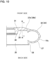
- FIG. 9 to FIG. 11 illustrate a fourth example of an embodiment of the present disclosure.
- the width dimension in the circumferential direction of each of the one side rib 37b and the other side rib 38b becomes smaller toward the outer side in the radial direction.
- the width dimension in the circumferential direction of each of the one side rib and the other side rib may be constant at a portion on the inner side in the radial direction, and may be reduced toward the outer side in the radial direction at a portion on the outer side in the radial direction.
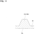
- each of the one side rib 37b and the other side rib 38b is a solid trapezoid as illustrated in FIG. 11 .
- the amount of protrusion toward the front side of each of the one side rib 37b and the other side rib 38b is constant at the portion on the inner side in the radial direction, and decreases toward the outer side in the radial direction at the portion on the outer side in the radial direction.
- the amount of protrusion of each of the one side rib and the other side rib toward the front side may also be reduced toward the outer side in the radial direction overall.
- the rigidity of the gear housing 16c can be adjusted not only by adjusting the overall length in the radial direction and the width dimension in the circumferential direction of each of the one side rib 37b and the other side rib 38b, but also by adjusting the rate of change of the width dimension in the circumferential direction with regard to the radial direction, the ratio of the length of the lower base to the length of the upper base of the trapezoidal cross-sectional shape, and the rate of change in the amount of protrusion toward the front side in the radial direction.
- the other configurations and operational effects are the same as in the first example.
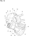
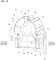
- FIG. 12 to FIG. 15 illustrate a fifth example of an embodiment of the present disclosure.
- the end portion on the one side in the axial direction of the worm 14 is supported by a ball bearing 40 so as to rotate and pivotally displace with respect to the fitting tubular portion for worm 32 on the one side in the axial direction of the worm housing section 27a.
- the end portion on the one side in the axial direction of the worm 14 is connected to the tip end portion of the output shaft 55a of the electric motor 17 using a coupling 60 so as to transmit torque and pivotally displace.
- the ball bearing 41 externally fitted onto the end portion on the other side in the axial direction of the worm 14 is internally fitted into the fitting tubular portion for worm 33 on the other side in the axial direction of the worm housing section 27a so as to move toward and away from the worm wheel 12 (in vertical direction in FIG. 12 ).
- the structure of this example includes an elastic biasing member 61 such as a leaf spring assembled between the fitting tubular portion for worm 33 on the other side in the axial direction and the ball bearing 41.
- the elastic biasing member 61 elastically biases the worm 14 toward the side of the worm wheel 12 through the ball bearing 41.
- backlash between the wheel teeth 13 and the worm teeth 15 is suppressed, suppressing chattering generated when the direction of rotation of the worm 14 is reversed.
- the worm housing section 27a of the gear housing 16d has a tubular shape with an end portion on the one side in the axial direction and an end portion on the other side in the axial direction open.
- the end portion on the other side in the axial direction of the worm housing section 27a is open, work such as assembling the elastic biasing member 61 can be easily performed through this opening.
- the opening on the other side in the axial direction of the worm housing section 27a is closed by a lid 62 attached to the opening.
- the worm housing section 27a of this example has a structure in which the end portion on the other side in the axial direction is open, the rigidity of the end portion on the other side in the axial direction tends to be lower compared to the worm housing section 27 of the first example in which the end portion on the other side in the axial direction is not open.
- a reinforcement level of the end portion on the other side in the axial direction of the worm housing section 27a by the other side rib 38c is made higher than a reinforcement level of the end portion on the one side in the axial direction of the worm housing section 27a by the one side rib 37c.
- the width dimension in the circumferential direction of the other side rib 38c is made larger than the width dimension in the circumferential direction of the one side rib 37c. In this way, by making the rigidity of the other side rib 38c greater than the rigidity of the one side rib 37c, the rigidity of the end portion on the other side in the axial direction of the worm housing section 27a is efficiently ensured.
- end portion on the outer side in the radial direction of the other side rib 38c is located farther from the fitting tubular portion for wheel 30 (lower side in FIG. 4 ) than the end portion on the outer side in the radial direction of the one side rib 37c in a direction orthogonal to the axial direction of the worm housing section 27a (vertical direction in FIG. 14 ).
- connection length of the end portion on the outer side in the radial direction of the other side rib 38c to the end portion on the other side in the axial direction of the worm housing section 27a is ensured to be longer than the connection length of the end portion on the outer side in the radial direction of the one side rib 37c to the end portion on the one side in the axial direction of the worm housing section 27a, so that the rigidity of the end portion on the other side in the axial direction of the worm housing section 27a is efficiently ensured.
- the overall amount of protrusion toward the front side of each of the one side rib 37c and the other side rib 38c is reduced toward the outer side in the radial direction, in other words, it is increased toward the inner side in the radial direction.
- the volume of each of the one side rib 37c and the other side rib 38c increases toward the inner side in the radial direction. Due to this, when performing inj ection molding or die casting of the gear housing 16d, the fluidity of material from the outer side in the radial direction to the inner side in the radial direction can be improved in each molding space of the one side rib 37c and the other side rib 38c.
- the gear housing 16d further includes an opposite side rib 63.
- the opposite side rib 63 protrudes from the side surface on the front side of the bottom portion for wheel 29.
- the opposite side rib 63 is arranged on the opposite side in the radial direction with respect to the one side rib 37c.
- the opposite side rib 63 extends in the radial direction centered on the center axis O of the bottom portion for wheel 29.
- the opposite side rib 63 is arranged on a center axis line ⁇ c of the one side rib 37c when viewed from the front side of the bottom portion for wheel 29.
- the opposite side rib 63 extends in a direction of the center axis line ⁇ c, that is, in the same direction as the one side rib 37c.
- the end portion on the inner side in the radial direction of the opposite side rib 63 is connected to the outer circumferential surface of the annular rib 31.
- the end portion on the outer side in the radial direction of the opposite side rib 63 is located at the end portion on the outer side in the radial direction of the bottom portion for wheel 29.
- This example further includes, optionally and additionally, an extension rib 64 that protrudes from the outer circumferential surface of the tubular portion for wheel 28 and extends from the end portion on the outer side in the radial direction of the opposite side rib 63 toward the rear side in the axial direction of the tubular portion for wheel 28.
- the end portion on the rear side of the extension rib 64 is located at the end portion on the rear side of the tubular portion for wheel 28.
- a hinge portion 35 is provided in the bottom portion for wheel 29 at a portion located on the opposite side in the radial direction with respires to the other side rib 38c.
- the rigidity of the portion located on the opposite side in the radial direction can be ensured by the hinge portion 35.
- the hinge portion when the hinge portion exists at a position in the circumferential direction that is different from this example, the rib on the opposite side that protrudes from the side surface on the front side of the bottom portion for wheel 29 may be arranged on the opposite side in the radial direction with respect to the other side rib 38c.
- an extension rib that protrudes from the outer circumferential surface of the tubular portion for wheel 28 and extends from the end portion on the outer side in the radial direction of the rib on the opposite side toward the rear side in the axial direction of the tubular portion for wheel 28.
- the gear housing 16d optionally and additionally includes a first rib 65.
- the first rib 65 protrudes from an end portion of the outer circumferential surface of the worm housing section 27a that is far from the wheel housing section 26 (lower side in FIG. 14 ) and extends in the axial direction of the worm housing section 27a.
- the first rib 65 is arranged over the entire length of the worm housing section 27a in the axial direction.
- the end portion on the one side in the axial direction of the first rib 65 is connected to the side surface on the other side in the axial direction of the motor mounting flange 34.
- the rigidity of the worm housing section 27a is efficiently ensured.
- the gear housing 16d optionally and additionally includes a second rib 66.
- the second rib 66 protrudes from the side surface on the front side of the bottom portion for wheel 29 and the side surface on the front side of the worm housing section 27a, and connects the fitting tubular portion for wheel 30 and the first rib 65.
- the second rib 66 is arranged on a straight line ⁇ that passes through the center axis O of the bottom portion for wheel 29 and is orthogonal to the center axis of the worm housing section 27a when viewed from the front side of the bottom portion for wheel 29.
- the end portion on the inner side in the radial direction of the second rib 66 is connected to the outer circumferential surface of the annular rib 31.
- the end portion on the outer side in the radial direction of the second rib 66 is connected to an intermediate portion in the extension direction of the first rib 65.
- the rigidity of the gear housing 16d is efficiently ensured.
- the gear housing 16d further includes a third rib 67.
- the third rib 67 extends from the end portion on the front side of the outer circumferential surface of the worm housing section 27a and extends in the axial direction of the worm housing section 27a.
- the third rib 67 is arranged in a portion on the one side in the axial direction of the worm housing section 27a. The end portion on the one side in the axial direction of the third rib 67 is connected to the side surface on the other side in the axial direction of the motor mounting flange 34.
- the end portion on the other side in the axial direction of the third rib 67 is located between the end portion on the outer side in the radial direction of the one side rib 37c and the end portion on the outer side in the radial direction of the other side rib 38c in the axial direction of the worm housing section 27a, more specifically, between the end portion on the outer side in the radial direction of the one side rib 37c and the second rib 66.
- the center axis line ⁇ c of the one side rib 37c intersects with the third rib 67 when viewed from the front side of the bottom portion for wheel 29.
- the rigidity of the worm housing section 27a is efficiently ensured.
- the center axis line ⁇ of the third rib 67 intersects with the center axis line ⁇ c of the other side rib 38c when viewed from the front side of the bottom portion for wheel 29. Further, when viewed from the front side of the bottom portion for wheel 29, the intersection of the center axis line ⁇ of the third rib 67 and the center axis line ⁇ c of the other side rib 38c overlaps with the fitting tubular portion for worm 33.
- the rigidity of the worm housing section 27a is more efficiently ensured.
- the other configurations and operational effects are the same as in the first example.
- FIG. 16 illustrates a sixth example of an embodiment of the present disclosure.
- opposite side ribs 63 are arranged at two locations on the opposite side in the radial direction from the one side rib 37c that are separated on both sides in the circumferential direction from the center axis line ⁇ c of the one side rib 37c.
- the two opposite side ribs 63 are arranged asymmetrically with respect to the center axis line ⁇ c, the two opposite side ribs 63 can also be arranged symmetrically with respect to the center axis line ⁇ c.
- the rigidity of the wheel housing section 26 is efficiently ensured by providing these opposite side ribs 63.
- the other configurations and operational effects are the same as in the fifth example.
- FIG. 17 illustrates a seventh example of an embodiment of the present disclosure.
- the hinge portion 35 is arranged at a position in the circumferential direction opposite to the worm housing section 27a in the radial direction.
- the gear housing 16f has fourth ribs 68 that each protrude from the side surface on the front side of the bottom portion for wheel 29 and are arranged at the same position in the circumferential direction as the bolt hole 59.
- Each of the fourth ribs 68 extends in a radial direction centered on the center axis O of the bottom portion for wheel 29.
- the end portion on the inner side in the radial direction of each of the fourth rib 68 is connected to the outer circumferential surface of the annular rib 31.
- the end portion on the outer side in the radial direction of each of the fourth rib 68 is located at the end portion on the outer side in the radial direction of the bottom portion for wheel 29.
- the rigidity of the wheel housing section 26 is efficiently ensured by providing these fourth ribs 68.
- the other configurations and operational effects are the same as in the fifth example.
- the structure of the present disclosure may be implemented by appropriately combining the structures of the respective embodiments described above to the extent that no contradiction occurs.
Landscapes
- Engineering & Computer Science (AREA)
- General Engineering & Computer Science (AREA)
- Mechanical Engineering (AREA)
- Chemical & Material Sciences (AREA)
- Combustion & Propulsion (AREA)
- Transportation (AREA)
- Gear Transmission (AREA)
- Power Steering Mechanism (AREA)
- General Details Of Gearings (AREA)
Applications Claiming Priority (2)
| Application Number | Priority Date | Filing Date | Title |
|---|---|---|---|
| JP2021173749 | 2021-10-25 | ||
| PCT/JP2022/037387 WO2023074304A1 (ja) | 2021-10-25 | 2022-10-06 | ギヤハウジングおよび電動アシスト装置 |
Publications (2)
| Publication Number | Publication Date |
|---|---|
| EP4425014A1 true EP4425014A1 (de) | 2024-09-04 |
| EP4425014A4 EP4425014A4 (de) | 2025-10-15 |
Family
ID=86159288
Family Applications (1)
| Application Number | Title | Priority Date | Filing Date |
|---|---|---|---|
| EP22886635.6A Pending EP4425014A4 (de) | 2021-10-25 | 2022-10-06 | Getriebegehäuse und elektrische hilfsvorrichtung |
Country Status (5)
| Country | Link |
|---|---|
| US (1) | US12466467B2 (de) |
| EP (1) | EP4425014A4 (de) |
| JP (1) | JP7492796B2 (de) |
| CN (2) | CN119196283A (de) |
| WO (1) | WO2023074304A1 (de) |
Family Cites Families (13)
| Publication number | Priority date | Publication date | Assignee | Title |
|---|---|---|---|---|
| US5287770A (en) * | 1992-11-25 | 1994-02-22 | Schiller-Pfeiffer, Inc. | Die cast transmission housing for rototiller |
| BR9609255A (pt) * | 1995-06-29 | 1999-05-18 | Teves Gmbh Alfred | Caixa para uma engrenagem |
| US6628026B2 (en) * | 2000-03-30 | 2003-09-30 | Asmo Co., Ltd. | Geared motor including ribbed gear housing |
| JP4746910B2 (ja) * | 2005-04-26 | 2011-08-10 | 株式会社 五十嵐電機製作所 | 電動アクチュエータ |
| EP2913246B1 (de) * | 2012-10-29 | 2019-03-27 | NSK Ltd. | Elektrische servolenkung |
| WO2016084659A1 (ja) * | 2014-11-25 | 2016-06-02 | 日本精工株式会社 | 電動式パワーステアリング装置用ハウジング |
| JP6658039B2 (ja) * | 2015-04-16 | 2020-03-04 | 日本精工株式会社 | 減速機及び電動式パワーステアリング装置 |
| CN106257103A (zh) * | 2015-06-19 | 2016-12-28 | 德昌电机(深圳)有限公司 | 驱动装置及其齿轮箱 |
| FR3041055B1 (fr) * | 2015-09-16 | 2017-10-06 | Jtekt Europe Sas | Reducteur a engrenage avec graisseur integre pour direction assistee |
| WO2019087946A1 (ja) * | 2017-10-30 | 2019-05-09 | 日本精工株式会社 | 電動パワーステアリング装置用ギヤハウジングおよびその製造方法、並びに、電動パワーステアリング装置 |
| CN111247050B (zh) * | 2017-10-30 | 2022-05-03 | 日本精工株式会社 | 电动助力转向装置用齿轮箱及其制造方法、电动助力转向装置 |
| JP6531882B1 (ja) * | 2018-01-15 | 2019-06-19 | 日本精工株式会社 | 電動式パワーステアリング装置用ギヤハウジング |
| US10400881B1 (en) * | 2018-08-22 | 2019-09-03 | Robert Bosch Gmbh | Gear case with mounting arm |
-
2022
- 2022-10-06 CN CN202411302042.0A patent/CN119196283A/zh active Pending
- 2022-10-06 US US18/703,087 patent/US12466467B2/en active Active
- 2022-10-06 EP EP22886635.6A patent/EP4425014A4/de active Pending
- 2022-10-06 CN CN202280061744.7A patent/CN117980631B/zh active Active
- 2022-10-06 WO PCT/JP2022/037387 patent/WO2023074304A1/ja not_active Ceased
- 2022-10-06 JP JP2023556261A patent/JP7492796B2/ja active Active
Also Published As
| Publication number | Publication date |
|---|---|
| WO2023074304A1 (ja) | 2023-05-04 |
| US12466467B2 (en) | 2025-11-11 |
| EP4425014A4 (de) | 2025-10-15 |
| JP7492796B2 (ja) | 2024-05-30 |
| JPWO2023074304A1 (de) | 2023-05-04 |
| CN117980631B (zh) | 2024-10-11 |
| CN119196283A (zh) | 2024-12-27 |
| CN117980631A (zh) | 2024-05-03 |
| US20240416989A1 (en) | 2024-12-19 |
Similar Documents
| Publication | Publication Date | Title |
|---|---|---|
| JP6151161B2 (ja) | ボールねじおよびパワーステアリング装置 | |
| US8376402B2 (en) | Lower type motor driven column apparatus | |
| US20130248278A1 (en) | Power steering device and housing for electric power steering device | |
| CN110775148A (zh) | 转向装置 | |
| KR102885510B1 (ko) | 스티어 바이 와이어식 조향장치 | |
| US20070295552A1 (en) | Electric power steering apparatus | |
| JP7122862B2 (ja) | 船外機 | |
| CN100369779C (zh) | 电动转向装置 | |
| US20200025282A1 (en) | Steering device | |
| CN109421786B (zh) | 电动转向柱装置 | |
| KR102662630B1 (ko) | 차량용 전동식 조향기어박스 | |
| EP4425014A1 (de) | Getriebegehäuse und elektrische hilfsvorrichtung | |
| JP2004314854A (ja) | 車両用操舵装置 | |
| US20090050400A1 (en) | Electric power steering apparatus | |
| JP2019006269A (ja) | ステアリング装置 | |
| US6006853A (en) | Cable-type steering device | |
| CN209650364U (zh) | 一种双输入轴电动助力转向器及汽车 | |
| JP2007285472A (ja) | 減速装置及びそれを備えた電動パワーステアリング装置 | |
| JP2010215094A (ja) | ラックアンドピニオン式ステアリング装置 | |
| JP7117204B2 (ja) | ステアリング装置 | |
| JP7842588B2 (ja) | ギヤハウジングおよび電動アシスト装置 | |
| JP2022064358A (ja) | ステアリング装置 | |
| JP3829045B2 (ja) | 電動パワーステアリング装置 | |
| JP2008195354A (ja) | ステアリング装置 | |
| JP2007216720A (ja) | 電動パワーステアリング装置 |
Legal Events
| Date | Code | Title | Description |
|---|---|---|---|
| STAA | Information on the status of an ep patent application or granted ep patent |
Free format text: STATUS: THE INTERNATIONAL PUBLICATION HAS BEEN MADE |
|
| PUAI | Public reference made under article 153(3) epc to a published international application that has entered the european phase |
Free format text: ORIGINAL CODE: 0009012 |
|
| STAA | Information on the status of an ep patent application or granted ep patent |
Free format text: STATUS: REQUEST FOR EXAMINATION WAS MADE |
|
| 17P | Request for examination filed |
Effective date: 20240502 |
|
| AK | Designated contracting states |
Kind code of ref document: A1 Designated state(s): AL AT BE BG CH CY CZ DE DK EE ES FI FR GB GR HR HU IE IS IT LI LT LU LV MC ME MK MT NL NO PL PT RO RS SE SI SK SM TR |
|
| DAV | Request for validation of the european patent (deleted) | ||
| DAX | Request for extension of the european patent (deleted) | ||
| REG | Reference to a national code |
Ref country code: DE Ref legal event code: R079 Free format text: PREVIOUS MAIN CLASS: F16H0057030000 Ipc: B62D0005040000 |
|
| A4 | Supplementary search report drawn up and despatched |
Effective date: 20250917 |
|
| RIC1 | Information provided on ipc code assigned before grant |
Ipc: B62D 5/04 20060101AFI20250911BHEP Ipc: F16H 57/03 20120101ALI20250911BHEP |